Table of Contents
Advertisement
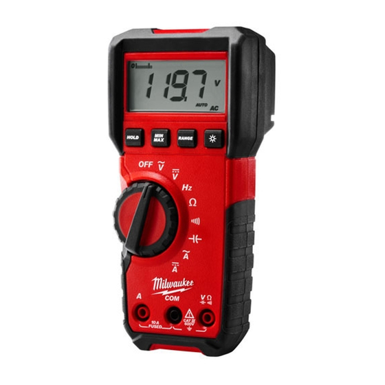
MILWAUKEE ELECTRIC TOOL CORPORATION – TEST & MEASUREMENT PRODUCT
REPAIR SERVICE INSTRUCTIONS — CALIBRATION
2216-20 Light Commercial Digital Multimeter
Perform all calibration at an ambient temperature of 23°C ± 2°C / 73.4°F ± 3.6°F and relative
Environmental
humidity of 80% - allow the digital multimeter to sit at this temperature for a minimum of 30
Condition
minutes before proceeding.
MI
LWAUKEE ELECTRIC TOOL CORPORAT
13135 WEST LISBON ROAD ● BROOKFIELD, WISCONSIN 53005-2550 ● USA
REPAIR SERVICE
INSTRUCTIONS
Calibration
58-92-2216d1 10/2010
ION
Advertisement
Table of Contents

Related Manuals for Milwaukee 2216-20


Summary of Contents for Milwaukee 2216-20
-
Page 1: Repair Service
MILWAUKEE ELECTRIC TOOL CORPORATION – TEST & MEASUREMENT PRODUCT REPAIR SERVICE INSTRUCTIONS — CALIBRATION 2216-20 Light Commercial Digital Multimeter Perform all calibration at an ambient temperature of 23°C ± 2°C / 73.4°F ± 3.6°F and relative Environmental humidity of 80% - allow the digital multimeter to sit at this temperature for a minimum of 30 Condition minutes before proceeding. -
Page 2: Table Of Contents
TABLE OF CONTENTS Page Introduction Precautions and Safety Information Symbols Safety Specifications General Specification Voltage Specification Current Specifications Resistance, Continuity, Capacitance Specifications Frequency, Rotary Switch, Auto Power Off Specification Physical and environment characteristics Certification and compliance Required Equipment Basic Maintenance Opening the Meter Case Replacing the Battery Testing Fuses... -
Page 3: Introduction
The information provided in this document is for the use of qualified personnel only. Caution The 2216-20 contain parts that can be damaged by static discharge. Follow the standard practices for handling static sensitive devices. Precautions and Safety Information Use the Meter only as described in the Users Manual. -
Page 4: Safety
SAFETY Review the following safety precautions to avoid injury and prevent damage to this product or any products connected to it. To avoid potential hazards, use the product only as specified. WARNING: These statements identify conditions or practices that could result in personal injury or loss of life. -
Page 5: Specifications
SPECIFICATIONS All specifications are warranted unless noted typical and apply to the 2216-20 DMM. Stated accuracies are at 23°C±5°C at than 80% relative humidity and without the battery indicator displayed. General specifications c i r y t i c i t Display "OL"... -
Page 6: Voltage Specification
Measurement Characteristics Accuracy is ±(% reading + number of digits) at 23°C ± 5°C, less than 80% R.H. Temperature coefficient: 0.1 * (Specified accuracy)/°C, < 18°C, > 28°C (1) DC Voltage Range Resolution Accuracy 600.0mV 0.1mV 6.000V 0.001V ±(0.5% reading + 2 digits) 60.00V 0.01V 600.0V... -
Page 7: Current Specifications
(3) DC Current Range Resolution Accuracy 6.000A 0.001A ±(1% reading + 3 digits) 10.00A 0.01A Response Time: < 1.5 sec. Maximum measurement time: 5 minutes at 10A with at least 20 minutes rest time. Overload Protection: AC/DC 20A for 10 second. (4) AC Current Range Resolution... -
Page 8: Resistance, Continuity, Capacitance Specifications
(6) Continuity Range Resolution Accuracy 600.0Ω 0.1Ω ±(1% reading + 5 digits) Open Circuit Voltage: Approx. 0.6V Continuity: Built-in buzzer sounds when measured resistance is less than 30Ω and sounds off when measured resistance is more than 200Ω, Between 30Ω to 200Ω the buzzer maybe sound or off either. -
Page 9: Frequency, Rotary Switch, Auto Power Off Specification
(11) Auto Power Off The meter automatically turns the power off after powering up and no operation for 20 ± 5 minutes. To power up, turn the knob back to OFF first. (12) Measuring Rate: 3 times/sec. (13) Fuse: 10A/600V Fast Action Fuse (14) Battery: Alkaline 1.5V Battery * 2 (15) Low Battery Voltage: 2.3V ±... -
Page 10: Physical And Environment Characteristics
Physical and Environmental Characteristics 170mm×80mm×57mm Dimensions (H×W×D) ° 0 Non-Operating -40 to +60°C y t i < i t l ) . t Non-Operating 12,300M (40354 ft.) Vibration & shock Operating MIL-PRF-28800F for Class 2 Instrument Certifications and compliances Safety Designed to IEC61010-1, UL61010-1 and CSA specifications Input rating Category lll 600V. -
Page 11: Required Equipment
Required Equipment Required equipment is listed in Table B. If the recommended models are not available, equipment with equivalent specifications may be used. Repairs or servicing should be performed only by qualified personnel. Table B. Required Equipment Equipment Required Characteristics Recommended Model AC Voltage Range: 0 ~... -
Page 12: Basic Maintenance
Basic Maintenance Warning To avoid shock, remove the test leads and any input signals before opening the case or replacing the battery or fuses. Opening the Meter Case Caution To avoid unintentional shock circuit, always place the uncovered Meter assembly on a protective surface. -
Page 13: Testing Fuses
Testing Fuses To test the internal fuses of the meter. 1. Turn the rotary selector switch to the Ω position. 2. To test FS1, plug a test lead into VΩHz input terminal, and touch the probe to the A input terminal. -
Page 14: Performance Tests
Testing the Display Rotate the dial from the "OFF" position to any other position. Check the LCD display segments when all segments are displayed. Compare the display with the example in Figure 2. LCD Graphics 2216-20 Figure 2 Display Test... -
Page 15: Testing The Voltage Function
Testing the Voltage Function To verify accuracy in the AC and DC voltage ranges, do the following: 1. Turn the rotary switch to “V ” position. 2. Connect the Calibrator to the VΩ and COM inputs on the Meter. 3. Set the Calibrator for the voltage and frequency from step 1 to 12 in Table 1. 4. -
Page 16: Testing The Resistance Function
Testing the Resistance Function To verify the accuracy of the resistance function, do the following: 1. Connect the Calibrator to VΩHz and COM on the Meter. 2. Turn the rotary switch to Ω. 3. Apply the inputs for step 1-6 in Table 3. 4. -
Page 17: Testing The Ampere Function
Testing the Ampere Function To verify the accuracy of AC current measurement functions, do the following: 1. Connect the Calibrator to the A and COM inputs on the Meter. 2. Turn the rotary switch to A~. 3. Apply the inputs for steps 1-4 in Table 5. 4. - Page 18 Table 7 Frequency Test: Step Source Level Waveform Reading 8.0Vp-p 2.00Hz Square Wave 1.98Hz to 2.02Hz 8.0Vp-p 80.00Hz Square Wave 79.90Hz to 80.10Hz 8.0Vp-p 800.0Hz Square Wave 799.0Hz to 801.0Hz 8.0Vp-p 8.000kHz Square Wave 7.990kHz to 8.010kHz 10.0Vp-p 50.00kHz Square Wave 49.93kHz to 50.07kHz 230.0Vp-p 10.00Hz...
-
Page 19: Calibration
Calibration Procedure Recalibrate the meter: It is recommended that the meter may be calibrated once year. Use the following procedure to calibrate the meter. Environmental Condition < Perform calibration at an ambient temperature and relative humidity (23°C±2°C and R.H. 80%). Allow the instrument to sit at this temperature for at least thirty minutes. - Page 20 (E) DCA Calibration (VR7) Rotate the rotary switch to DCA Function. Connect the output of a DCA calibrator to V and COM input terminals of the meter. Output DCA 5.000A from the calibrator. Adjust VR7 until the display shows 5.000A ± 0.001A. Turn off the output of the calibrator and disconnect the meter from the calibrator.