Icom IC-7800 User Manual
Hide thumbs
Also See for IC-7800:
- Service manual addendum (555 pages) ,
- Instruction manual (230 pages) ,
- Service manual (216 pages)
Table of Contents
Advertisement
Quick Links
I Screen menu arrangement
The following screens can be selected from the start
up screen. Choose the desired screen using the fol-
lowing chart.
• Spectrum scope screen (p. 5-2)
• Voice recorder screen (p. 7-3)
• Memory keyer screen (CW mode; p. 4-8)
• RTTY decoder screen (p. 4-13)
Pushing [EXIT/SET] several times returns to the start
up screen. See p. 12-3 for set mode arrangement.
• PSK31 decoder screen (p. 4-21)
• Memory channel screen (p. 8-3)
• Scan screen (VFO mode; p. 9-4)
• Scan screen (Memory mode; p. 9-6)
• Set mode menu screen (p. 12-2)
1-15
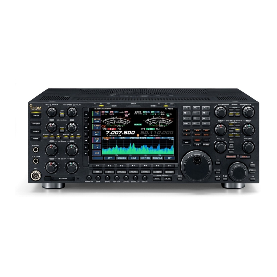
PANEL DESCRIPTION
1
Advertisement
Table of Contents

Related Manuals for Icom IC-7800


Summary of Contents for Icom IC-7800
-
Page 1: Screen Menu Arrangement
PANEL DESCRIPTION I Screen menu arrangement The following screens can be selected from the start Pushing [EXIT/SET] several times returns to the start up screen. Choose the desired screen using the fol- up screen. See p. 12-3 for set mode arrangement. lowing chart. -
Page 2: D Convenient Functions For Transmit
RECEIVE AND TRANSMIT D D Convenient functions for transmit • Break-in function (p. 6-3) ➥ Push [VOX/BK-IN] several times to select the break-in OFF, semi break-in and full break-in. • “BK IN” or “F-BK IN” appears when the semi break-in or full break-in function is ON, respectively. -
Page 3: I Operating Rtty (Fsk)
RECEIVE AND TRANSMIT I Operating RTTY (FSK) A DSP-based high-quality Baudot RTTY encoder/de- coder is built-in to the IC-7800. When connecting a PC keyboard (p. 2-6), RTTY operation can be performed without an external RTTY terminal, TNC or PC. If you would rather use your RTTY terminal or TNC, consult the manual that comes with the RTTY terminal or TNC. -
Page 4: D Functions For The Rtty Decoder Indication
RECEIVE AND TRANSMIT D D Functions for the RTTY decoder indication q Push a band key to select the desired band. [F-6•MAIN/SUB] [F-7•WIDE] w Push [RTTY/PSK] to select RTTY. • After RTTY mode is selected, push [RTTY/PSK] for 1 sec. to toggle between RTTY and RTTY-R modes. •... - Page 5 RECEIVE AND TRANSMIT D D RTTY decode set mode This set mode is used to set the decode USOS func- tion, time stamp setting, etc. • Setting contents q During RTTY mode operation, push [F-3•DECODE] [F-3•Ω ≈] [F-7•WIDE] to select RTTY decode screen. w Push [F-1•<MENU2>] to select RTTY decode menu 2, then push [F-6•SET] to select RTTY decode set mode.
- Page 6 RECEIVE AND TRANSMIT D D RTTY decode set mode (continued) Explicitly inserts the FIGS character even thought it is • ON : Inserts FIGS. not required by the receiving station. • OFF : Does not insert FIGS. Turn the time stamp (date, transmission or reception •...
-
Page 7: I Operating Psk
RECEIVE AND TRANSMIT I Operating PSK A high-quality DSP-based PSK31 encoder/decoder is built-in to the IC-7800. When connecting a PC key- board (p. 2-6), PSK31 operation can be performed without PSK software installed on your PC. If desired, you can also use your PSK software; con- sult the manual that comes with the software. -
Page 8: D Functions For The Psk Decoder Indication
RECEIVE AND TRANSMIT D D Functions for the PSK decoder indication q Push a band key to select the desired band. [F-3•AFC/NET] [F-6•MAIN/SUB] [F-7•WIDE] w Push [RTTY/PSK] to select PSK. • After PSK mode is selected, push [RTTY/PSK] for 1 sec. to toggle between PSK and PSK-R modes. - Page 9 RECEIVE AND TRANSMIT D D PSK decode set mode This set mode is used to set the decode USOS func- tion, time stamp setting, etc. • Setting contents q During PSK mode operation, push [F-3•DECODE] [F-3•Ω ≈] [F-7•WIDE] to select PSK decode screen. w Push [F-1•<MENU2>] to select PSK decode menu 2, then push [F-6•SET] to select PSK decode set mode.
- Page 10 RECEIVE AND TRANSMIT D D PSK decode set mode (continued) Selects the operating frequency display for time • ON : Displays the operating frequency. stamp usage. • OFF : No operating frequency display. NOTE: The frequency won’t be displayed when “OFF”...
-
Page 11: Set Mode
SET MODE D D Screen arrangement • Display set mode (p. 12-11) • Set mode menu screen (p. 12-2) • Time set mode (p. 11-2) • Level set mode (p. 12-4) • Miscellaneous (Others) set mode (p. 12-14) • ACC set mode (p. 12-6) •... -
Page 12: I Level Set Mode
SET MODE I Level set mode (continued) Sets the bass level of the receive audio tone in FM mode from –5 to +5. (default: 0) Sets the treble level of the receive audio tone in FM mode from –5 to +5. (default: 0) Sets the transmission passband width to wide setting Lower freq. -
Page 13: I Display Set Mode
SET MODE I Display set mode Adjusts the LCD unit brightness from 0 (dark) to 100% (bright) range in 1% steps. (default: 50%) Adjusts the switch indicators brightness from 1 (dark) to 100 (bright) range in 1 steps. (default: 80) Selects the desired display type from A, B and C. - Page 14 SET MODE I Display set mode (continued) Sets the memory name indication, during memory • ON : The programmed memory name is displayed mode operation, ON and OFF. (default: ON) above the frequency indication. • OFF : No memory name is displayed even a mem- ory name is programmed.
-
Page 15: I Swr Reading
52V V I Screen type and font selections 3 types of screen images and 18 types of frequency readout indication fonts are available in the IC-7800. • Screen image example— type C q Push [EXIT/SET] several times to close multi-func- tion screen, if necessary. -
Page 16: Control Command
CONTROL COMMAND D D Command table Command Sub command Description Command Sub command Description — Send frequency data — Select/read attenuator (0=OFF; 1=3 dB; 2=6 dB; 3=9 dB; 4=12 dB; Same as Send mode data 5=15 dB; 6=18 dB; 7=21 dB) command 06 00 + RX ANT Select/read ANT1 selection... - Page 17 CONTROL COMMAND D D Command table (continued) Command Sub command Description Command Sub command Description 050134 Send/read voice memory short 050164 Send/read scan speed play time (3=3 sec. to 10=10 sec.) (0=Low, 1=High) 050135 Send/read voice memory normal 050165 Send/read scan resume record time (0=OFF, 1=ON) (5= 5 sec.
- Page 18 CONTROL COMMAND D D Command table (continued) Command Sub command Description 050190 Set/read FFT scope averaging set for RTTY decoder (0=OFF, 1=2, 2=3, 3=4) 050191 Set/read FFT scope waveform color set for RTTY decoder (see p. 14-10 for details) 050192 Set/read FFT scope averaging set for PSK decoder (0=OFF, 1=2, 2=3, 3=4)
- Page 19 CONTROL COMMAND D D Offset frequency setting D D Color setting The following data sequence is used when sending or The following data sequence is used when sending or reading the offset frequency setting. reading the color setting. X X X X X X X X X R (Red)