Table of Contents
Advertisement
®
.3
.6
I n s t a l l a t i o n
I n s t a l l a t i o n
I n s t a l l a t i o n a n d
I n s t a l l a t i o n
I n s t a l l a t i o n
100 Watt Amplifier
2 - c h a n n e l
150 Watt Amplifier
2-channel w/crossover
.6
300 Watt Amplifier
4-channel w/crossover
a n d
a n d
O p e r a t i o n
O p e r a t i o n
a n d
a n d O p e r a t i o n
O p e r a t i o n
O p e r a t i o n
®
Advertisement
Table of Contents

Related Manuals for Rockford Fosgate 2.3


Summary of Contents for Rockford Fosgate 2.3
- Page 1 ® ® 100 Watt Amplifier 2 - c h a n n e l 150 Watt Amplifier 2-channel w/crossover 300 Watt Amplifier 4-channel w/crossover I n s t a l l a t i o n I n s t a l l a t i o n a n d a n d O p e r a t i o n...
-
Page 2: Practice Safe Sound
Congratulations on your purchase of the world's finest brand of car audio amplifiers. At Rockford Fosgate we are fanatics about musical reproduction at its best, and we are pleased you chose our product. Through years of engineering expertise, hand craftsman- ship and critical testing procedures, we have created a wide range of products that reproduce music with all the clarity and richness you deserve. -
Page 3: Table Of Contents
Installation Section of this manual or refer to the icons listed below. Other information can be located by using the Table of Contents. We, at Rockford Fosgate, have worked very hard to make sure all the information in this manual is current. But, as we are constantly finding new ways to improve our product, this information is subject to change without notice. -
Page 4: Introduction
N T R O D U C T I O N This manual provides information on the features, installation and opera- tion of the Rockford Fosgate 2.3, 2.6x and 4.6x Amplifiers. We suggest you save this manual for future reference. - Page 5 THE RESULT: Elimination of troublesome ground loop noise between source and amplifier. MOSFET Devices Rockford Fosgate is one of the few manufacturers in the sound community to utilize MOSFET devices in both the power supply and the output stages . MOSFET (Metal Oxide Semiconductor Field Effect Transistor) devices offer several important inherent advantages over the 30 year old technology of bi-polar design.
- Page 6 The DSM (Discrete Surface Mount) manufacturing process combines the advantages of both discrete components and integrated circuitry. Rockford Fosgate is the only American amplifier manufacturer to have invested millions into this process. DSM components differ from conventional discrete components in different ways. They are more compact, more rugged, and they efficiently dissipate generated heat.
- Page 7 High Level Inputs The high level inputs on the Rockford Fosgate amplifiers convert the speaker line outputs (high level) to preamp line inputs (low level). This allows amplifier compatibility with a variety of source units as well as the ability to integrate into factory systems without the need for external adapters.
-
Page 8: 2.6X, 4.6X Design Features
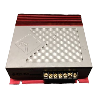
2.3, 2.6 , 4.6 E S I G N E AT U R E S Bias Bias & CAUTION! Do Not Adjust Speaker Speaker High In REM GND Gain Input + – + – L&R Bias Bias Bias Bias CAUTION! - Page 9 1. Extruded Heatsink The extruded aluminum heatsink of the RF amplifier dissipates heat generated by the amplifier's circuitry. 2. Power/Speaker Barrier Strip The barrier strip uses screw terminals that will accept #10 spade lugs or bare speaker and power wire sizes from 10-18 AWG. These gold-plated connectors are immune to corrosion that will cause signal degradation.
-
Page 10: Installation Considerations
N S TA L L AT I O N O N S I D E R AT I O N S The following is a list of tools you will need for installing the amplifier: Wire Cutters #2 Phillips Screwdriver Wire Strippers Assorted wire connectors Wire Crimpers... -
Page 11: Mounting Location
Engine Compartment Mounting Rockford Fosgate amplifiers should never be mounted in the engine compartment. Not only will this void your warranty but could create an embarrassing situation caused by the ridicule from your friends. -
Page 12: Battery And Charging
Rockford amplifier without problems, although battery and alternator life can be reduced slightly. To maximize the performance of your Rockford Fosgate amplifier, we suggest the use of a heavy duty battery, high output alternator and an energy storage capacitor. - Page 13 Trim the power cable within 18" of the battery and strip 1/2" of insulation from the end of the wire. here Cut the wire loop that is attached to the fuseholder in half and splice the fuse into the power line using appropriate inline connectors.
-
Page 14: Using Passive Crossovers
CAUTION: The Rockford Fosgate amplifiers are not recom- mended for impedance loads below 2 stereo and 4 bridged (mono) loads. -
Page 15: Table Of Crossover Component Values
2.2 F 12000 25 H 6.6 F 51 H 3.3 F 100 H 1.6 F 6 dB/Octave High-Pass and Low-Pass Filters L = Low-Pass (Inductor) C = High-Pass (Capacitor) For more information, see your Authorized Rockford Fosgate Dealer. – 12 –... -
Page 16: Using The Xcard
S I N G T H E The crossover functions are controlled through the use of an XCard and can be set for high-pass, low-pass or full range operation. The 100Hz XCard shipped with your amplifier is set for Full Range. Each crossover card has two faces: one face operates Full Range, the other has arrows to indicate the edge for selecting HP (high-pass) or LP (low- pass) operation. -
Page 17: Resistor Chart
ESISTOR HART Our tests have shown that using 0.047 f capacitors for frequencies below 100Hz, and 0.022 f capacitors for frequencies above 100Hz, result in more linear crossover control. Refer to the Specifications page to determine the capacitor value of each supplied XCard. -
Page 18: Xcard Access
CCESS The internal XCard crossover(s) are accessible by removing the top cover from the amplifier. The XCard should be inserted with the filter side (HP, LP or FULL RANGE) facing the metal contacts inside the socket (toward RCA jacks). Bias Bias Bias Bias... -
Page 19: 2.6X Installation
® ® 2.3 & 2.6 NSTALLATION High Level Input – “Single Ended” Type This configuration is used for source units that have “Single Ended” speaker outputs. Only the “+” output is “hot,” whereas the “–” or “common” are common grounded. To verify your source unit has these outputs, connect an ohm meter across the “–”... -
Page 20: Power Connections
® ® Power Connections ® ® High In Speaker Speaker Speaker Speaker High In Gain REM GND Input LF- R F + R F - L R - L R + RR- RR+ Gain Input + – + – + – + –... -
Page 21: Mono Operation
® ® Mono Operation ® ® Speaker Speaker High In Gain Input + – + – – 4 Min. • RCA Inputs are connected to both left and right inputs • Impedance Load for mono channel should be 4 minimum •... - Page 22 ® ® NSTALLATION High Level Input – “Single Ended” Type This configuration is used for source units that have “Single Ended” speaker outputs. Only the “+” output is “hot,” whereas the “–” or “common” are common grounded. To verify your source unit has these outputs, connect an ohm meter across the “–” output and radio chassis for a reading of 0 .
- Page 23 ® ® Power Connections ® ® High In Speaker Speaker Speaker Speaker High In Gain L F + L F - Input R F + R F - L R - L R + Gain R R - R R + Input + –...
- Page 24 ® ® 2-Channel Mono Operation ® ® High In Speaker Speaker Speaker Speaker High In Gain L F + L F - Input R F + R F - L R - L R + R R - R R + Gain Input + –...
- Page 25 ® ® 4-Channel Stereo Operation ® ® High In Speaker Speaker Speaker Speaker High In Gain Input L F + L F - R F + R F - L R - L R + Gain R R - R R + Input + –...
- Page 26 ® ® 4-Channel Stereo/Dual Mono Operation ® ® High In High In Speaker Speaker Speaker Speaker Gain Input L F + L F - R F + R F - L R - L R + Gain R R - R R + Input + –...
-
Page 27: System Diagrams
6kHz-20kHz – – 18dB/octave HP – – 100Hz-6kHz – 6dB/octave BP 20Hz-100Hz 6dB/octave LP *Refer to Table of Crossover Component Values on page 12 or ask your local Authorized Rockford Fosgate Dealer for selecting proper capacitor/coil values. – 24 –... - Page 28 Rear Left Rear Right – – 100Hz-20kHz 12dB/octave HP – 20Hz-100Hz 6dB/octave LP – *Refer to Table of Crossover Component Values on page 12 or ask your local Authorized Rockford Fosgate Dealer for selecting proper capacitor/coil values. – 25 –...
- Page 29 150 Watt System (rated @ 4 ohms) Total Power Delivery (RMS) Tweeters 90 Watts Midrange 90 Watts Woofer 120 Watts *Refer to Table of Crossover Component Values on page 12 or ask your local Authorized Rockford Fosgate Dealer for selecting proper capacitor/coil values. – 26 –...
- Page 30 300 Watt System (rated @ 4 ohms) Total Power Delivery (RMS) Tweeters 120 Watts Midrange 120 Watts Woofers 120 Watts *Refer to Table of Crossover Component Values on page 12 or ask your local Authorized Rockford Fosgate Dealer for selecting proper capacitor/coil values. – 27 –...
-
Page 31: Troubleshooting
R O U B L E S H O O T I N G TROUBLE-S Symptom Diagnosis Remedy Amplifier does not Voltage applied to the Check the alternator, bat- turn on REM terminal of the tery, fuse, and wiring and (Power LED is off) amplifier is not between repair as necessary. - Page 32 TROUBLE-S Symptom Diagnosis Remedy Readjust input gains of Speaker Output Input gain signal for amplifier. Low or Distorted amplifier is incorrectly set. Check system with known Source unit output too working source and repair low or source unit has or replace original source no output.
- Page 33 No reference ground Engine Noise with Connect GND terminal of high level input to chassis high level inputs of source unit. • If noise persists, see your Authorized Rockford Fosgate Dealer. – 30 –...
-
Page 34: Dynamic Power Measurements
Y N A M I C O W E R E A S U R E M E N T S About the Dynamic Power Measurements The Audio Graph PowerCube is a test instrument used to measure the output of an amplifier in accordance with IHF-202 industry standards. The IHF-202 standard is a dynamic power measurement and was developed as a means of measuring power in a manner that best represents the Real World operation of an amplifier. - Page 35 Information Cubed The data acquired in the testing procedure is then graphed in the form of a 3-dimensional cube, hence the name PowerCube. The Phase Angle is expressed on the horizontal axis, the Output Voltage is presented on the vertical axis and the Impedance is displayed on the Z axis.
-
Page 36: Specifications
– 33 –... - Page 37 – 34 –...
-
Page 38: Warranty Information
• Who is Covered This warranty covers only the original purchaser of Rockford product purchased from an Authorized Rockford Fosgate Dealer in the United States. In order to receive service, the purchaser must provide Rockford with a copy of the receipt stating the customer name, dealer name, product purchased and date of purchase. -
Page 39: International Information
– 36 –... - Page 40 NTRODUCCIÓN Este manual le provee de información de las caracteristicas, instalación y funcionamiento de los amplificadores Rockford Fosgate 2.3, 2.6x y 4.6x. Le sugerimos guardar éste manual para futuras referéncias. Recomendamos que contacte con un distribuidor autorizado por Rock- ford Fosgate para la instalación de su nuevo Amplificador.
- Page 41 Funcionamiento Stereo/Mono ® ® Speaker Speaker High In Gain Input + – + – – – 2 Min. 2 Min. – 4 Min. • Las entradas RCA están conectadas a ambas entradas, derecha e izquierda • Impedancia de carga para cada canal estereo deben haber como minimo 2 Ohmios •...
- Page 42 Funcionamiento con 4 canales Stereo y uno Mono ® ® High In High In Speaker Speaker Speaker Speaker Gain Gain L F + L F - Input R F + R F - L R - L R + R R - R R + Input + –...
- Page 43 N T R O D U C T I O N Ce manuel offre des informations sur les caractéristiques, l'installation et le foncionnement des amplificateurs Rockford Fosgate 2.3, 2.6x et 4.6x. Nous vous proposons de conserver ce manuel pour toute référence future.
- Page 44 Installation stéréo/mono ® ® Speaker Speaker High In Gain Input + – + – – – 2 Min. 2 Min. – 4 Min. • l'entrée signal est connectée à l'entrée gauche et droite. • la charge d'impédance pour chaque canal stéréo sera de 2 minimum •...
- Page 45 Installation 4 canaux stéréo/mono ® ® High In High In Speaker Speaker Speaker Speaker Gain Gain Input L F + L F - R F + R F - L R - L R + R R - R R + Input + –...
- Page 46 Ihr Fahrzeug und das Produkt vor Beschädigung schützen. INLEITUNG Diese Bedienungsanleitung enthält Informationen über Features und den Einbau der Rockford Fosgate 2.3, 2.6x und 4.6 Verstärker. Wir empfehlen Ihnen diese Bedienungsanleitung sorgfältig aufzubewahren. Wir raten Ihnen Ihren Verstärker nur von einem authorisierten Rockford Fosgate-Händler einbauen zu lassen, sollten Sie die Montage selber...
- Page 47 Mono/Stereo Betrieb ® ® Speaker Speaker High In Gain Input + – + – – – Min. Min. – Min. • RCA-Eingänge an den rechten und linken Eingangs-Buchsen verbinden • Die Impedanz-Last für jeden Stereo Kanal sollte mindestens 2 Ohm betragen •...
- Page 48 4-Kanal Stereo/Single Betrieb ® ® High In High In Speaker Speaker Speaker Speaker Gain Gain Input L F + L F - R F + R F - L R - L R + R R - R R + Input + –...
- Page 49 NTRODUZIONE Questo manuale offre informazioni sulle caratteristiche, sull'installazione, e sul funzionamento degli amplificatori Rockford Fosgate 2.3, 2.6x e 4.6x. Vi suggeriamo di conservare questo manuale per riferimento futuro. Noi raccomandiamo fortemente di far installare il vostro nuovo amplificatore da un installatore autorizzato. Se invece preferite installare da soli il vostro amplificatore, assicuratevi di leggere l'intero manuale prima di cominciare.
- Page 50 Funzionamento Stereo/Mono ® ® Speaker Speaker High In Gain Input + – + – – – Min. Min. – Min. • Gli ingressi RCA sono collegati sia sull'ingresso sinstro e estro • L'impedenza minima per ciascun canale stereo deve essere 2 •...
- Page 51 Funzionamento a 4 canali stereo con mono simultaneo ® ® High In High In Speaker Speaker Speaker Speaker Gain Gain L F + L F - Input R F + R F - L R - L R + R R - R R + Input + –...
- Page 52 American companies. However, due to the global nature of their manufacturing facilities and the electronics parts industry in general, some parts may be manufactured in other countries. Rockford Fosgate Rockford Corporation 546 South Rockford Drive Tempe, Arizona 85281 U.S.A.