Table of Contents
Advertisement
Safety Instructions
& Operator's Manual for
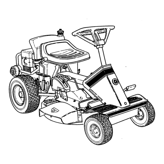
REAR ENGINE RIDING MOWER
SERIES 16
MODELS
250816B
N250816B
250816BE
N250816BE
281016BE
N281016BE
301016BE
301216BE
331416BVE
331416KVE
PRECIX
BODYI
SUFFIXI
INi281 8i,6
B El
MODEL
_
SERIES
DESIGNATION
I
DESIGNATION
•
ENGINE
r-
HP
ENGINE &
CUTTING
OPTIONS
WIDTH
i
MODEL NUMBER EXPLANATION
PREFIX EXPLANATiON
N- California Model
25 - 25" Cutting Width
28.28"
Cutting Width
30.30"
Cutting Width
33.33"
Cutting Width
BODY EXPLANATION
08.8.0
HP Engine
12.12.0
HP Engine
10.10.0
HP Engine
14.14.0
HP Engine
SUFFIX EXPLANATION
16. Series DesignaHon
B. BHggs Engine
V. Overhead Valve
E. Electric Start
Thank you for buying a SNAPPER
Product!
Before operating your REAR ENGINE RIDER, read this manual carefully
and pay particular
attention to the "IMPORTANT
SAFETY
INSTRUCTIONS"
on Page 2.
Remember
that all power
equipment
can be dangerous
if used improperly.
Also keep in mind that SAFETY requires careful use in accordance
with the operating instructions
and common sense!
COPYRIGHT
O 1997
SNAPPER
INC
ALL RIGHTS
RESERVED
MANUAL No. 3-5620 (REV. 1, 9/97)
Advertisement
Table of Contents

Related Manuals for Snapper SERIES 16 250816B


Summary of Contents for Snapper SERIES 16 250816B
- Page 1 SERIES DESIGNATION DESIGNATION • ENGINE ENGINE & CUTTING OPTIONS WIDTH Thank you for buying a SNAPPER and pay particular attention to the "IMPORTANT equipment can be dangerous if used improperly. with the operating instructions and common sense! COPYRIGHT O 1997...
-
Page 2: Important Safety Instructions
If you have any questions pertaining to your machine which your dealer cannot answer to your satisfaction, call or write the Customer Service Department at SNAPPER, McDonough, Georgia 30253. Phone: (770) 954-2500. -
Page 3: Section 1 - Familiarization
VENT FILLER DECK MOWER LEVER FIGURE 1.1 1.2 NOMENCLATURE The nomenclature drawing above, Figure 1.1, shows the essential parts of the SNAPPER Rear Engine Rider. It is procedures recommended become thoroughly components, SAFETY operating. found in the separate engine owner's manual. -
Page 4: Section 2 -Operating
Section 2 -OPERATING PRE-START CHECK UST Make the following checks and perform the service required before each start-up. 2.1.1. Check tires and add or release air as needed to bring pressure to 15 psi in front and 10 psi in rear tires. 2.1.2. -
Page 5: Section 2 - Operating Instructions
Section 2 - OPERATING INSTRUCTIONS 2.3 STARTING & OPERATION 2.3.1 ENGINE (ELECTRIC START) IMPORTANT: When the ignition key is turned to "START", the engine will turn over, but will not start unless the Clutch/Brake pedal is pressed all the way down, the Blade Lever is in the "OFF"... -
Page 6: Mower Blade
Section 2- OPERATING INSTRUCTIONS 2.3.1 ENGINE (ELECTRIC START) (Continued) Should the battery be too weak to start the engine, use the instructions shown below, 2.3.2., (MANUAL START) to manually start the electric start en- gines. On Model 331416BVE, the engine is equipped with a fuel shut-off solenoid. - Page 7 Section 2 - OPERATING INSTRUCTIONS CAUTION Before leaving the Rear Engine Rider with the engine running, STOP the blade, shift to neutral and engage the park brake. 2.4 STOPPING 2.4.1. ENGINE 1. Stop engine by turning key to the "OFF" position. See Figure 2.11.
-
Page 8: Wheel Drive
Section 2 - OPERATING 2.4.4. PARK BRAKE (Continued) 2. Release park brake by pushing down on the Clutch/Brake Pedal to release park brake lever. See Figure 2.15. PUSH CLUTCWBRAKE PEDAL ALL THE WAY DOWN FIGURE 2.15 2.4.5. CUTTING HEIGHT ADJUSTMENT 1. -
Page 9: Section 3 - Maintenance
For the correct part or information for a particular Rear Engine Riding Mower, always mention the model and sedal number. SNAPPER recommends retuming the Rear Engine Rider to an authorized SNAPPER dealer annually for inspection and addition of any new devices which might upgrade the safety of the Rear Engine Rider. - Page 10 Section 3 - MAINTENANCE 3.2.3. CHECK MOWER DRIVE BELT 1. Drive Belt Cover Removal a. Lower deck to lowest setting. b. Remove four self-tapping screws, two on each side of mower drive belt cover. See Figure 3.3. c. Slide cover back and rotate out on left side of mower deck.
-
Page 11: Mower Components
However, those powered by 8HP, 9HP, or 12HP engines, the left rear axle bearing requires SNAPPER =00" general purpose grease from grease gun. See Figure 3.8. (Continued) all grass on rear shots... - Page 12 EVERY TWO YEARS In addition to regular maintenance, the following components of the Rear Engine Rider should be carefully damage. genuine SNAPPER from an authorized SNAPPER dealer. 3.5.1. visible, 3.5.2. dealer for service. (END OF EACH SEASON) For complete maintenance schedule, see ENGINE 1.
-
Page 13: Every Two Years
Section 3 - MAINTENANCE EVERY TWO YEARS 3.5.3. Transmission shift lever and detent. 3.5.4. Clutch disc. 3.5.5. Clutch Yoke (See Figure 4.18 on Page 18). 3.5.6. Mower deck linkage and pivot areas. STORAGE (OUT OF SEASON) If desired, the Rear Engine Rider can be stored on rear bumper. -
Page 14: Section 4 - Adjustments & Repair
SNAPJN FRAME SPACER--.,_ ASSEMBLY IMPORTANT: and flat washers Model is shipped with additional spacers specifically designed for the Rear Engine Rider. forward until spacers be required, contact an authorized SNAPPER dealer. HAIRPIN SNAPJN FRAME PIVOT CHANNEL STUD "PIVOT FLAT WASHERS FIGURE 4.2... -
Page 15: Blade Brake Adjustment
Section 4 - ADJUSTMENTS & REPAIR CAUTION Before performing service procedures, always remove switch, remove spark plug wire from spark plug and secure spark plug wire away from spark plug. 4.2.2. BLADE BRAKE ADJUSTMENT 1. Remove Belt Cover; 3.2.3, on Page 9. 2. - Page 16 Section 4 - ADJUSTMENTS 4.2.4. MOWER DECK ADJUSTMENT 1. Side-To-Side Before making deck leveling adjustments, check the tire pressure. Front tires 15 psi, rear tires 10 psi. If tires are properly inflated and mowing is still uneven, adjustside-to-side deck levelness as follows: a.
- Page 17 It is set to maintain the deck in the same attitude through all heights of cut. If suspecting timing adjustment, contact an authorized SNAPPER dealer for service. See Figure 4.12. ADJUSTMENT OF THE TIMING ROD SHOULD ONLY BE DONE BY AN AUTHORIZ FIGURE 4.12...
-
Page 18: Wheel Brake Adjustment
PEDAL ARM FIGURE 4.16 & REPAIR or repairs, stop spark plug NOT.___E: I f adjustment cannot be completed or made because all ferrules authorized SNAPPER dealer for service. 4.3.3. PUSH CLUTCH/BRAKE PEDAL ALL THE WAY DRIVE DISC pedal to FERRULES 7. -
Page 19: Blade Sharpening
Section 4 - ADJUSTMENTS & REPAIR 3. Measure the distance between end of clutch/brake cable and bottom of housing. Measurement should be no less than 112" and no greater than 3/4". See inset, Figure 4.18. CHAIN- CASE HOUSING CABLE COTTER-, FIGURE 4.18 4. - Page 20 Section 4 - ADJUSTMENTS & REPAIR 3. Inspect condition of blade. Figure 4.20. 4. If blade is in good condition, sharpen at 22 to 28 degrees. DO NOT sharpen beyond existing cutting edge. See Figure 4.22. I DO NOT SHARPEN BEYOND ORIGINAL CUTTING EDGE...
- Page 21 Section 4 -ADJUSTMENTS 4.6.2. BELT REPLACEMENT Adjust bait guide. proper bait-to-belt guide clearances. 10. Check mower drive adjust if necessary. Refer to 4.2.1., MOWER DRIVE BELT ADJUSTMENT 11. Reinstall mowerdrive 26" MODELS ._6" N=== O MINAL 28", 30"_ & 33" MODELS 1116"...
- Page 22 Section 4 - ADJUSTMENTS & REPAIR CAUTION The electrolyte (acid) produces a highly explosive gas. Keep all sparks, flame and fire away from area when charging battery or when handling battery. Electrolyte (acid) is a highly corrosive liquid. Wear eye protection. Wash affected areas immediately after having eye or skin contact with electrolyte (acid).
- Page 23 Section 4 - ADJUSTMENTS & REPAIR 4.6.5. BATTERY TESTING State of Charcje 100% Charged w/Sulfate Stop 100% Charged 75% Charged 50% Charged 25% Charged 0% Charcjed Methods of Checking Battery Condition Syringe Hydrometer Digita! Voltmeter 1.280 1.265 1.210 1.160 1.120 Less than 1.100 Lessthan 11o80v ACCESSORIES...
-
Page 24: Maintenance Schedule
SUBJECT SERVICE TO BE PERFORMED Engine Check Oil Level Engine Initial Oil Change Engine Periodic Oil Change Air Pre-Cleaner Service Sponge Pre- Cleaner Element Air Cleaner Replace Element Spark Plug Replace Plugs Fuel Filter Replace Filter Clean Shrouds & Fins Engine Cooling System Battery... -
Page 25: Year Limited Warranty
For five (5) years from purchase date for original purchaser's residential non-commercial _' use, Snapper, through any Snapper dealer will replace free of charge any part or parts found upon examination by the factory to be defective in material or workmanship or both. -
Page 26: Service Notes
SERVICE NOTES... - Page 27 SERVICE NOTES...
- Page 28 California to cause cancer, birth defects or other reproductive harm. The engine exhaust from this product contains chemicals known to the State of I 8NAPPER,coo°o°o,. o,.. _o=_ u.s.,. COPYRIGHT © 1997 SNAPPER INC. ALL RIGHTS RESERVED MANUAL No. 3-5620 (REV. 1, 9/97) & Operator's Manual for...
- Page 29 SERIES DESIGNATION DESIGNATION • ENGINE ENGINE & CUTTING OPTIONS WIDTH Thank you for buying a SNAPPER and pay particular attention to the "IMPORTANT equipment can be dangerous if used improperly. with the operating instructions and common sense! COPYRIGHT O 1997...
-
Page 30: Important Safety Instructions
If you have any questions pertaining to your machine which your dealer cannot answer to your satisfaction, call or write the Customer Service Department at SNAPPER, McDonough, Georgia 30253. Phone: (770) 954-2500. -
Page 31: Control Panel
VENT FILLER DECK MOWER LEVER FIGURE 1.1 1.2 NOMENCLATURE The nomenclature drawing above, Figure 1.1, shows the essential parts of the SNAPPER Rear Engine Rider. It is procedures recommended become thoroughly components, SAFETY operating. found in the separate engine owner's manual. - Page 32 Section 2 -OPERATING PRE-START CHECK UST Make the following checks and perform the service required before each start-up. 2.1.1. Check tires and add or release air as needed to bring pressure to 15 psi in front and 10 psi in rear tires. 2.1.2.
-
Page 33: Section 2 - Operating Instructions
Section 2 - OPERATING INSTRUCTIONS 2.3 STARTING & OPERATION 2.3.1 ENGINE (ELECTRIC START) IMPORTANT: When the ignition key is turned to "START", the engine will turn over, but will not start unless the Clutch/Brake pedal is pressed all the way down, the Blade Lever is in the "OFF"... -
Page 34: Mower Blade
Section 2- OPERATING INSTRUCTIONS 2.3.1 ENGINE (ELECTRIC START) (Continued) Should the battery be too weak to start the engine, use the instructions shown below, 2.3.2., (MANUAL START) to manually start the electric start en- gines. On Model 331416BVE, the engine is equipped with a fuel shut-off solenoid. - Page 35 Section 2 - OPERATING INSTRUCTIONS CAUTION Before leaving the Rear Engine Rider with the engine running, STOP the blade, shift to neutral and engage the park brake. 2.4 STOPPING 2.4.1. ENGINE 1. Stop engine by turning key to the "OFF" position. See Figure 2.11.
-
Page 36: Wheel Drive
Section 2 - OPERATING 2.4.4. PARK BRAKE (Continued) 2. Release park brake by pushing down on the Clutch/Brake Pedal to release park brake lever. See Figure 2.15. PUSH CLUTCWBRAKE PEDAL ALL THE WAY DOWN FIGURE 2.15 2.4.5. CUTTING HEIGHT ADJUSTMENT 1. -
Page 37: Section 3 - Maintenance
For the correct part or information for a particular Rear Engine Riding Mower, always mention the model and sedal number. SNAPPER recommends retuming the Rear Engine Rider to an authorized SNAPPER dealer annually for inspection and addition of any new devices which might upgrade the safety of the Rear Engine Rider. - Page 38 Section 3 - MAINTENANCE 3.2.3. CHECK MOWER DRIVE BELT 1. Drive Belt Cover Removal a. Lower deck to lowest setting. b. Remove four self-tapping screws, two on each side of mower drive belt cover. See Figure 3.3. c. Slide cover back and rotate out on left side of mower deck.
-
Page 39: Mower Components
However, those powered by 8HP, 9HP, or 12HP engines, the left rear axle bearing requires SNAPPER =00" general purpose grease from grease gun. See Figure 3.8. (Continued) all grass on rear shots... - Page 40 EVERY TWO YEARS In addition to regular maintenance, the following components of the Rear Engine Rider should be carefully damage. genuine SNAPPER from an authorized SNAPPER dealer. 3.5.1. visible, 3.5.2. dealer for service. (END OF EACH SEASON) For complete maintenance schedule, see ENGINE 1.
-
Page 41: Every Two Years
Section 3 - MAINTENANCE EVERY TWO YEARS 3.5.3. Transmission shift lever and detent. 3.5.4. Clutch disc. 3.5.5. Clutch Yoke (See Figure 4.18 on Page 18). 3.5.6. Mower deck linkage and pivot areas. STORAGE (OUT OF SEASON) If desired, the Rear Engine Rider can be stored on rear bumper. -
Page 42: Section 4 - Adjustments & Repair
SNAPJN FRAME SPACER--.,_ ASSEMBLY IMPORTANT: and flat washers Model is shipped with additional spacers specifically designed for the Rear Engine Rider. forward until spacers be required, contact an authorized SNAPPER dealer. HAIRPIN SNAPJN FRAME PIVOT CHANNEL STUD "PIVOT FLAT WASHERS FIGURE 4.2... -
Page 43: Blade Brake Adjustment
Section 4 - ADJUSTMENTS & REPAIR CAUTION Before performing service procedures, always remove switch, remove spark plug wire from spark plug and secure spark plug wire away from spark plug. 4.2.2. BLADE BRAKE ADJUSTMENT 1. Remove Belt Cover; 3.2.3, on Page 9. 2. - Page 44 Section 4 - ADJUSTMENTS 4.2.4. MOWER DECK ADJUSTMENT 1. Side-To-Side Before making deck leveling adjustments, check the tire pressure. Front tires 15 psi, rear tires 10 psi. If tires are properly inflated and mowing is still uneven, adjustside-to-side deck levelness as follows: a.
- Page 45 It is set to maintain the deck in the same attitude through all heights of cut. If suspecting timing adjustment, contact an authorized SNAPPER dealer for service. See Figure 4.12. ADJUSTMENT OF THE TIMING ROD SHOULD ONLY BE DONE BY AN AUTHORIZ FIGURE 4.12...
-
Page 46: Wheel Brake Adjustment
PEDAL ARM FIGURE 4.16 & REPAIR or repairs, stop spark plug NOT.___E: I f adjustment cannot be completed or made because all ferrules authorized SNAPPER dealer for service. 4.3.3. PUSH CLUTCH/BRAKE PEDAL ALL THE WAY DRIVE DISC pedal to FERRULES 7. -
Page 47: Blade Sharpening
Section 4 - ADJUSTMENTS & REPAIR 3. Measure the distance between end of clutch/brake cable and bottom of housing. Measurement should be no less than 112" and no greater than 3/4". See inset, Figure 4.18. CHAIN- CASE HOUSING CABLE COTTER-, FIGURE 4.18 4. - Page 48 Section 4 - ADJUSTMENTS & REPAIR 3. Inspect condition of blade. Figure 4.20. 4. If blade is in good condition, sharpen at 22 to 28 degrees. DO NOT sharpen beyond existing cutting edge. See Figure 4.22. I DO NOT SHARPEN BEYOND ORIGINAL CUTTING EDGE...
- Page 49 Section 4 -ADJUSTMENTS 4.6.2. BELT REPLACEMENT Adjust bait guide. proper bait-to-belt guide clearances. 10. Check mower drive adjust if necessary. Refer to 4.2.1., MOWER DRIVE BELT ADJUSTMENT 11. Reinstall mowerdrive 26" MODELS ._6" N=== O MINAL 28", 30"_ & 33" MODELS 1116"...
- Page 50 Section 4 - ADJUSTMENTS & REPAIR CAUTION The electrolyte (acid) produces a highly explosive gas. Keep all sparks, flame and fire away from area when charging battery or when handling battery. Electrolyte (acid) is a highly corrosive liquid. Wear eye protection. Wash affected areas immediately after having eye or skin contact with electrolyte (acid).
- Page 51 Section 4 - ADJUSTMENTS & REPAIR 4.6.5. BATTERY TESTING State of Charcje 100% Charged w/Sulfate Stop 100% Charged 75% Charged 50% Charged 25% Charged 0% Charcjed Methods of Checking Battery Condition Syringe Hydrometer Digita! Voltmeter 1.280 1.265 1.210 1.160 1.120 Less than 1.100 Lessthan 11o80v ACCESSORIES...
-
Page 52: Maintenance Schedule
SUBJECT SERVICE TO BE PERFORMED Engine Check Oil Level Engine Initial Oil Change Engine Periodic Oil Change Air Pre-Cleaner Service Sponge Pre- Cleaner Element Air Cleaner Replace Element Spark Plug Replace Plugs Fuel Filter Replace Filter Clean Shrouds & Fins Engine Cooling System Battery... -
Page 53: Year Limited Warranty
For five (5) years from purchase date for original purchaser's residential non-commercial _' use, Snapper, through any Snapper dealer will replace free of charge any part or parts found upon examination by the factory to be defective in material or workmanship or both. -
Page 54: Service Notes
SERVICE NOTES... - Page 55 SERVICE NOTES...
- Page 56 California to cause cancer, birth defects or other reproductive harm. The engine exhaust from this product contains chemicals known to the State of I 8NAPPER,coo°o°o,. o,.. _o=_ u.s.,. COPYRIGHT © 1997 SNAPPER INC. ALL RIGHTS RESERVED MANUAL No. 3-5620 (REV. 1, 9/97) & Operator's Manual for...
- Page 57 SERIES DESIGNATION DESIGNATION • ENGINE ENGINE & CUTTING OPTIONS WIDTH Thank you for buying a SNAPPER and pay particular attention to the "IMPORTANT equipment can be dangerous if used improperly. with the operating instructions and common sense! COPYRIGHT O 1997...
-
Page 58: Important Safety Instructions
If you have any questions pertaining to your machine which your dealer cannot answer to your satisfaction, call or write the Customer Service Department at SNAPPER, McDonough, Georgia 30253. Phone: (770) 954-2500. -
Page 59: Control Panel
VENT FILLER DECK MOWER LEVER FIGURE 1.1 1.2 NOMENCLATURE The nomenclature drawing above, Figure 1.1, shows the essential parts of the SNAPPER Rear Engine Rider. It is procedures recommended become thoroughly components, SAFETY operating. found in the separate engine owner's manual. - Page 60 Section 2 -OPERATING PRE-START CHECK UST Make the following checks and perform the service required before each start-up. 2.1.1. Check tires and add or release air as needed to bring pressure to 15 psi in front and 10 psi in rear tires. 2.1.2.
-
Page 61: Section 2 - Operating Instructions
Section 2 - OPERATING INSTRUCTIONS 2.3 STARTING & OPERATION 2.3.1 ENGINE (ELECTRIC START) IMPORTANT: When the ignition key is turned to "START", the engine will turn over, but will not start unless the Clutch/Brake pedal is pressed all the way down, the Blade Lever is in the "OFF"... -
Page 62: Mower Blade
Section 2- OPERATING INSTRUCTIONS 2.3.1 ENGINE (ELECTRIC START) (Continued) Should the battery be too weak to start the engine, use the instructions shown below, 2.3.2., (MANUAL START) to manually start the electric start en- gines. On Model 331416BVE, the engine is equipped with a fuel shut-off solenoid. - Page 63 Section 2 - OPERATING INSTRUCTIONS CAUTION Before leaving the Rear Engine Rider with the engine running, STOP the blade, shift to neutral and engage the park brake. 2.4 STOPPING 2.4.1. ENGINE 1. Stop engine by turning key to the "OFF" position. See Figure 2.11.
-
Page 64: Wheel Drive
Section 2 - OPERATING 2.4.4. PARK BRAKE (Continued) 2. Release park brake by pushing down on the Clutch/Brake Pedal to release park brake lever. See Figure 2.15. PUSH CLUTCWBRAKE PEDAL ALL THE WAY DOWN FIGURE 2.15 2.4.5. CUTTING HEIGHT ADJUSTMENT 1. -
Page 65: Section 3 - Maintenance
For the correct part or information for a particular Rear Engine Riding Mower, always mention the model and sedal number. SNAPPER recommends retuming the Rear Engine Rider to an authorized SNAPPER dealer annually for inspection and addition of any new devices which might upgrade the safety of the Rear Engine Rider. - Page 66 Section 3 - MAINTENANCE 3.2.3. CHECK MOWER DRIVE BELT 1. Drive Belt Cover Removal a. Lower deck to lowest setting. b. Remove four self-tapping screws, two on each side of mower drive belt cover. See Figure 3.3. c. Slide cover back and rotate out on left side of mower deck.
-
Page 67: Mower Components
However, those powered by 8HP, 9HP, or 12HP engines, the left rear axle bearing requires SNAPPER =00" general purpose grease from grease gun. See Figure 3.8. (Continued) all grass on rear shots... - Page 68 EVERY TWO YEARS In addition to regular maintenance, the following components of the Rear Engine Rider should be carefully damage. genuine SNAPPER from an authorized SNAPPER dealer. 3.5.1. visible, 3.5.2. dealer for service. (END OF EACH SEASON) For complete maintenance schedule, see ENGINE 1.
-
Page 69: Every Two Years
Section 3 - MAINTENANCE EVERY TWO YEARS 3.5.3. Transmission shift lever and detent. 3.5.4. Clutch disc. 3.5.5. Clutch Yoke (See Figure 4.18 on Page 18). 3.5.6. Mower deck linkage and pivot areas. STORAGE (OUT OF SEASON) If desired, the Rear Engine Rider can be stored on rear bumper. -
Page 70: Section 4 - Adjustments & Repair
SNAPJN FRAME SPACER--.,_ ASSEMBLY IMPORTANT: and flat washers Model is shipped with additional spacers specifically designed for the Rear Engine Rider. forward until spacers be required, contact an authorized SNAPPER dealer. HAIRPIN SNAPJN FRAME PIVOT CHANNEL STUD "PIVOT FLAT WASHERS FIGURE 4.2... -
Page 71: Blade Brake Adjustment
Section 4 - ADJUSTMENTS & REPAIR CAUTION Before performing service procedures, always remove switch, remove spark plug wire from spark plug and secure spark plug wire away from spark plug. 4.2.2. BLADE BRAKE ADJUSTMENT 1. Remove Belt Cover; 3.2.3, on Page 9. 2. - Page 72 Section 4 - ADJUSTMENTS 4.2.4. MOWER DECK ADJUSTMENT 1. Side-To-Side Before making deck leveling adjustments, check the tire pressure. Front tires 15 psi, rear tires 10 psi. If tires are properly inflated and mowing is still uneven, adjustside-to-side deck levelness as follows: a.
- Page 73 It is set to maintain the deck in the same attitude through all heights of cut. If suspecting timing adjustment, contact an authorized SNAPPER dealer for service. See Figure 4.12. ADJUSTMENT OF THE TIMING ROD SHOULD ONLY BE DONE BY AN AUTHORIZ FIGURE 4.12...
-
Page 74: Wheel Brake Adjustment
PEDAL ARM FIGURE 4.16 & REPAIR or repairs, stop spark plug NOT.___E: I f adjustment cannot be completed or made because all ferrules authorized SNAPPER dealer for service. 4.3.3. PUSH CLUTCH/BRAKE PEDAL ALL THE WAY DRIVE DISC pedal to FERRULES 7. -
Page 75: Blade Sharpening
Section 4 - ADJUSTMENTS & REPAIR 3. Measure the distance between end of clutch/brake cable and bottom of housing. Measurement should be no less than 112" and no greater than 3/4". See inset, Figure 4.18. CHAIN- CASE HOUSING CABLE COTTER-, FIGURE 4.18 4. - Page 76 Section 4 - ADJUSTMENTS & REPAIR 3. Inspect condition of blade. Figure 4.20. 4. If blade is in good condition, sharpen at 22 to 28 degrees. DO NOT sharpen beyond existing cutting edge. See Figure 4.22. I DO NOT SHARPEN BEYOND ORIGINAL CUTTING EDGE...
- Page 77 Section 4 -ADJUSTMENTS 4.6.2. BELT REPLACEMENT Adjust bait guide. proper bait-to-belt guide clearances. 10. Check mower drive adjust if necessary. Refer to 4.2.1., MOWER DRIVE BELT ADJUSTMENT 11. Reinstall mowerdrive 26" MODELS ._6" N=== O MINAL 28", 30"_ & 33" MODELS 1116"...
- Page 78 Section 4 - ADJUSTMENTS & REPAIR CAUTION The electrolyte (acid) produces a highly explosive gas. Keep all sparks, flame and fire away from area when charging battery or when handling battery. Electrolyte (acid) is a highly corrosive liquid. Wear eye protection. Wash affected areas immediately after having eye or skin contact with electrolyte (acid).
- Page 79 Section 4 - ADJUSTMENTS & REPAIR 4.6.5. BATTERY TESTING State of Charcje 100% Charged w/Sulfate Stop 100% Charged 75% Charged 50% Charged 25% Charged 0% Charcjed Methods of Checking Battery Condition Syringe Hydrometer Digita! Voltmeter 1.280 1.265 1.210 1.160 1.120 Less than 1.100 Lessthan 11o80v ACCESSORIES...
-
Page 80: Maintenance Schedule
SUBJECT SERVICE TO BE PERFORMED Engine Check Oil Level Engine Initial Oil Change Engine Periodic Oil Change Air Pre-Cleaner Service Sponge Pre- Cleaner Element Air Cleaner Replace Element Spark Plug Replace Plugs Fuel Filter Replace Filter Clean Shrouds & Fins Engine Cooling System Battery... -
Page 81: Year Limited Warranty
For five (5) years from purchase date for original purchaser's residential non-commercial _' use, Snapper, through any Snapper dealer will replace free of charge any part or parts found upon examination by the factory to be defective in material or workmanship or both. -
Page 82: Service Notes
SERVICE NOTES... - Page 83 SERVICE NOTES...
- Page 84 California to cause cancer, birth defects or other reproductive harm. The engine exhaust from this product contains chemicals known to the State of I 8NAPPER,coo°o°o,. o,.. _o=_ u.s.,. COPYRIGHT © 1997 SNAPPER INC. ALL RIGHTS RESERVED MANUAL No. 3-5620 (REV. 1, 9/97) & Operator's Manual for...
- Page 85 SERIES DESIGNATION DESIGNATION • ENGINE ENGINE & CUTTING OPTIONS WIDTH Thank you for buying a SNAPPER and pay particular attention to the "IMPORTANT equipment can be dangerous if used improperly. with the operating instructions and common sense! COPYRIGHT O 1997...
- Page 86 If you have any questions pertaining to your machine which your dealer cannot answer to your satisfaction, call or write the Customer Service Department at SNAPPER, McDonough, Georgia 30253. Phone: (770) 954-2500.
- Page 87 VENT FILLER DECK MOWER LEVER FIGURE 1.1 1.2 NOMENCLATURE The nomenclature drawing above, Figure 1.1, shows the essential parts of the SNAPPER Rear Engine Rider. It is procedures recommended become thoroughly components, SAFETY operating. found in the separate engine owner's manual.
- Page 88 Section 2 -OPERATING PRE-START CHECK UST Make the following checks and perform the service required before each start-up. 2.1.1. Check tires and add or release air as needed to bring pressure to 15 psi in front and 10 psi in rear tires. 2.1.2.
-
Page 89: Section 2 - Operating Instructions
Section 2 - OPERATING INSTRUCTIONS 2.3 STARTING & OPERATION 2.3.1 ENGINE (ELECTRIC START) IMPORTANT: When the ignition key is turned to "START", the engine will turn over, but will not start unless the Clutch/Brake pedal is pressed all the way down, the Blade Lever is in the "OFF"... - Page 90 Section 2- OPERATING INSTRUCTIONS 2.3.1 ENGINE (ELECTRIC START) (Continued) Should the battery be too weak to start the engine, use the instructions shown below, 2.3.2., (MANUAL START) to manually start the electric start en- gines. On Model 331416BVE, the engine is equipped with a fuel shut-off solenoid.
- Page 91 Section 2 - OPERATING INSTRUCTIONS CAUTION Before leaving the Rear Engine Rider with the engine running, STOP the blade, shift to neutral and engage the park brake. 2.4 STOPPING 2.4.1. ENGINE 1. Stop engine by turning key to the "OFF" position. See Figure 2.11.
- Page 92 Section 2 - OPERATING 2.4.4. PARK BRAKE (Continued) 2. Release park brake by pushing down on the Clutch/Brake Pedal to release park brake lever. See Figure 2.15. PUSH CLUTCWBRAKE PEDAL ALL THE WAY DOWN FIGURE 2.15 2.4.5. CUTTING HEIGHT ADJUSTMENT 1.
-
Page 93: Section 3 - Maintenance
For the correct part or information for a particular Rear Engine Riding Mower, always mention the model and sedal number. SNAPPER recommends retuming the Rear Engine Rider to an authorized SNAPPER dealer annually for inspection and addition of any new devices which might upgrade the safety of the Rear Engine Rider. - Page 94 Section 3 - MAINTENANCE 3.2.3. CHECK MOWER DRIVE BELT 1. Drive Belt Cover Removal a. Lower deck to lowest setting. b. Remove four self-tapping screws, two on each side of mower drive belt cover. See Figure 3.3. c. Slide cover back and rotate out on left side of mower deck.
- Page 95 However, those powered by 8HP, 9HP, or 12HP engines, the left rear axle bearing requires SNAPPER =00" general purpose grease from grease gun. See Figure 3.8. (Continued) all grass on rear shots...
- Page 96 EVERY TWO YEARS In addition to regular maintenance, the following components of the Rear Engine Rider should be carefully damage. genuine SNAPPER from an authorized SNAPPER dealer. 3.5.1. visible, 3.5.2. dealer for service. (END OF EACH SEASON) For complete maintenance schedule, see ENGINE 1.
- Page 97 Section 3 - MAINTENANCE EVERY TWO YEARS 3.5.3. Transmission shift lever and detent. 3.5.4. Clutch disc. 3.5.5. Clutch Yoke (See Figure 4.18 on Page 18). 3.5.6. Mower deck linkage and pivot areas. STORAGE (OUT OF SEASON) If desired, the Rear Engine Rider can be stored on rear bumper.
-
Page 98: Section 4 - Adjustments & Repair
SNAPJN FRAME SPACER--.,_ ASSEMBLY IMPORTANT: and flat washers Model is shipped with additional spacers specifically designed for the Rear Engine Rider. forward until spacers be required, contact an authorized SNAPPER dealer. HAIRPIN SNAPJN FRAME PIVOT CHANNEL STUD "PIVOT FLAT WASHERS FIGURE 4.2... - Page 99 Section 4 - ADJUSTMENTS & REPAIR CAUTION Before performing service procedures, always remove switch, remove spark plug wire from spark plug and secure spark plug wire away from spark plug. 4.2.2. BLADE BRAKE ADJUSTMENT 1. Remove Belt Cover; 3.2.3, on Page 9. 2.
- Page 100 Section 4 - ADJUSTMENTS 4.2.4. MOWER DECK ADJUSTMENT 1. Side-To-Side Before making deck leveling adjustments, check the tire pressure. Front tires 15 psi, rear tires 10 psi. If tires are properly inflated and mowing is still uneven, adjustside-to-side deck levelness as follows: a.
- Page 101 It is set to maintain the deck in the same attitude through all heights of cut. If suspecting timing adjustment, contact an authorized SNAPPER dealer for service. See Figure 4.12. ADJUSTMENT OF THE TIMING ROD SHOULD ONLY BE DONE BY AN AUTHORIZ FIGURE 4.12...
- Page 102 PEDAL ARM FIGURE 4.16 & REPAIR or repairs, stop spark plug NOT.___E: I f adjustment cannot be completed or made because all ferrules authorized SNAPPER dealer for service. 4.3.3. PUSH CLUTCH/BRAKE PEDAL ALL THE WAY DRIVE DISC pedal to FERRULES 7.
- Page 103 Section 4 - ADJUSTMENTS & REPAIR 3. Measure the distance between end of clutch/brake cable and bottom of housing. Measurement should be no less than 112" and no greater than 3/4". See inset, Figure 4.18. CHAIN- CASE HOUSING CABLE COTTER-, FIGURE 4.18 4.
- Page 104 Section 4 - ADJUSTMENTS & REPAIR 3. Inspect condition of blade. Figure 4.20. 4. If blade is in good condition, sharpen at 22 to 28 degrees. DO NOT sharpen beyond existing cutting edge. See Figure 4.22. I DO NOT SHARPEN BEYOND ORIGINAL CUTTING EDGE...
- Page 105 Section 4 -ADJUSTMENTS 4.6.2. BELT REPLACEMENT Adjust bait guide. proper bait-to-belt guide clearances. 10. Check mower drive adjust if necessary. Refer to 4.2.1., MOWER DRIVE BELT ADJUSTMENT 11. Reinstall mowerdrive 26" MODELS ._6" N=== O MINAL 28", 30"_ & 33" MODELS 1116"...
- Page 106 Section 4 - ADJUSTMENTS & REPAIR CAUTION The electrolyte (acid) produces a highly explosive gas. Keep all sparks, flame and fire away from area when charging battery or when handling battery. Electrolyte (acid) is a highly corrosive liquid. Wear eye protection. Wash affected areas immediately after having eye or skin contact with electrolyte (acid).
- Page 107 Section 4 - ADJUSTMENTS & REPAIR 4.6.5. BATTERY TESTING State of Charcje 100% Charged w/Sulfate Stop 100% Charged 75% Charged 50% Charged 25% Charged 0% Charcjed Methods of Checking Battery Condition Syringe Hydrometer Digita! Voltmeter 1.280 1.265 1.210 1.160 1.120 Less than 1.100 Lessthan 11o80v ACCESSORIES...
- Page 108 SUBJECT SERVICE TO BE PERFORMED Engine Check Oil Level Engine Initial Oil Change Engine Periodic Oil Change Air Pre-Cleaner Service Sponge Pre- Cleaner Element Air Cleaner Replace Element Spark Plug Replace Plugs Fuel Filter Replace Filter Clean Shrouds & Fins Engine Cooling System Battery...
- Page 109 For five (5) years from purchase date for original purchaser's residential non-commercial _' use, Snapper, through any Snapper dealer will replace free of charge any part or parts found upon examination by the factory to be defective in material or workmanship or both.
-
Page 110: Service Notes
SERVICE NOTES... - Page 111 SERVICE NOTES...
- Page 112 California to cause cancer, birth defects or other reproductive harm. The engine exhaust from this product contains chemicals known to the State of I 8NAPPER,coo°o°o,. o,.. _o=_ u.s.,. COPYRIGHT © 1997 SNAPPER INC. ALL RIGHTS RESERVED MANUAL No. 3-5620 (REV. 1, 9/97) & Operator's Manual for...