Table of Contents
Advertisement
0
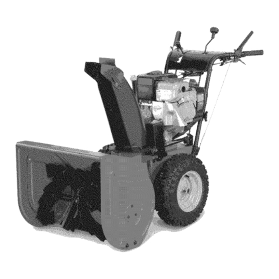
Simplicil#
0
A
ATO
AL
'S
Large
tame
Snowthrow_rs
960
Models
Mfg. No.
Description
1694602
9247E, 9HP Snowthrower
1694589
9560E, 9.5HP Snowthrower
1694597
9560M, 9.5HP Snowthrower
(CE)
1694606
E9247, 9HP Snowthrower (CE)
1 060
Niodels
Mfg. No.
Description
1694590
1060E, 10HP Snowthrower
1694598
1060M, 10HP Snowthrower (CE)
1070
Models
Mfg. No.
Description
1694603
10287E, IOHP Snowthrower
1694607
E10287, IONP Snowthrower (CE)
1170
Models
IVlfg. No.
Description
1694591
1170E, 11liP Snowthrower
1694599
1170M, 11liP Snowthrower (CE)
1180
Models
Mfg. No.
Description
1694604
11327E, 11liP Snowthrower
1694608
E11327, 11HP Snowthrower (CE)
1280
Models
Mfg. No.
Description
1694592
1280E, 12HP Snowthrower
1694600
1280M, 12HP Snowthrower (CE)
1290
Models
Mfg. No.
Description
1694605
12387E, 12HP Snowthrower
1694609
E12387, 12HP Snowthrower (CE)
1390
Models
IVlfg. No.
Description
1694593
1390E, 13HP Snowthrower
1694601
1390M, 13HP Snowthrower (CE)
TP
1727040
Revision
01
Rev. Date
5/2004
I00-4059-01-LW-S
Advertisement
Table of Contents

Related Manuals for Simplicity 960


Summary of Contents for Simplicity 960
- Page 1 Simplicil# Large tame Snowthrow_rs 1180 Models Models Mfg. No. Description Mfg. No. Description 1694604 11327E, 11liP Snowthrower 1694602 9247E, 9HP Snowthrower 1694608 E11327, 11HP Snowthrower (CE) 1694589 9560E, 9.5HP Snowthrower 1694597 9560M, 9.5HP Snowthrower (CE) 1280 Models 1694606 E9247, 9HP Snowthrower (CE) Mfg.
- Page 2 (able ofContents CONTENTS: Regular Maintenance Schedule ............Safety Rules & information Checking Tire Pressure ......... Training ............Auger Gear Case Lubrication ......Preparation ............Lubrication ............. Operation ............Check/Lubricate Free-Hand Linkage ... 18 Children ............Lubricate the Auger Shaft & Assembly ..
- Page 3 This machine is capable of amputating hands and feet. Read these safety rules and follow them closely. Failure to obey these rules could result in loss of control of unit, severe personal injury or death to you, or bystanders, or damage to property or equipment. The triangle in text signifies important cautions or warnings which must be followed.
-
Page 4: Shut Off The Engine
Safety Rules 21.Keepin mind theoperator i sresponsible f oracci- 8. Always follow the engine manual instructions for stor- dentsoccurring tootherpeople or property. age preparations before storing the unit for both short 22.Dataindicates t hatoperators, age60yearsand and long term periods. above, a reinvolved ina largepercentage of power 9. -
Page 6: North American
DecaJs DECALS The safety decals below are on your unit. This unit has been designed and manufactured to pro- vide you with the safety and reliability you would expect If any of these decals are lost or damaged, replace them from an industry leader in outdoor power equipment. -
Page 7: Safety Icons
Safety icons SAFETY iCONS WARNING: READ OPERATOR'S WARNING: DISMEMBERMENT. MANUAL. This machine can amputate limbs. Read and understand the Operator's Keep bystanders and children away Manual before using this machine. when engine is running. DANGER: THROWN OBJECTS. DANGER: DISMEMBERMENT. This machine is capable of throwing The auger can amputate limbs. -
Page 8: Identification Numbers
D. Maximum Engine Speed in Rotations per Minute LpA: XXX dB(A) E. Manufacturer's Address - Vibration: XXX m/a 2 F. Year of Manufacture Simplicity Mfg. Inc. G. CE Compliance Logo f'Port Washington, Wl USA 53074-0997 H. Mass of Unit in Kilograms I. Sound Power in Decibels *** J. -
Page 9: Features, C Ontrols, & Operation
Features, C ontrols, & Operation Please take a moment and familiarize yourseff with the name, location, function of these controls so that you will better understand the safety and operating instructions provided in this manual Manual Electric Rotator Rotator Model Model CONTROL LOCATIONS... -
Page 10: Features And Controls
Features & Controls Auger Control Engages the auger/impeller when depressed. Releasing Fuel tank filler cap (see illustration). Note: The fuel shut off valve is located under the fuel tank or on the front of the control stops the auger/impeller. the engine. Close the valve when the snowthrower is not in use. -
Page 11: General Operation
OperatJofl GENERAL OPERATION WARNING CHECKS BEFORE EACH START-UP This unit is a "two=stage" snowthrower. The first stage is the auger, which feeds the snow 1. Make sure all safety guards are in place and all nuts, back into the impeller housing. The second stage bolts and clips are secure. -
Page 12: Starting The Engine
OperstJon STARTING CONTROLS See Figure 1for the following instructions. Units with Optional Electric Start Electric Start Button - The Electric Start Button (A) activates an electric starter mounted to the engine, eliminating the need to pull the starter han- dle. The Electric Start Button operates on 120 Volts AC, which is provided by connection to the extension cord provided with units equipped with this feature. -
Page 13: Operating The Snowthrower
Operatiofl OPERATING THE SNOWTHROWER WARNING 1. Rotate the discharge chute to the desired direction. When BOTH levers are depressed, the Free- 2. Set the speed selector to the desired forward speed. Hand Control is activated. This allows Auger Engage Control to be released -- YET AUGER 3. -
Page 14: Operation
Operation DEFLECTOR The distance of the discharged snow is mainly controlled by the position of the deflector. (Engine speed also affects distance of discharge.) The more the deflector is tilted UP, the farther snow will be thrown. ModeJs with Chute Deflector Knob See Figure 3. - Page 15 OperatJofl FULL TRACTION EASY TURN TRACTION _'_EasyTurnTM _"" Easy Turn Lever Lever Released Engaged Right Wheel Freewheels, Both Wheels Drive Left Wheel Drives Figure 6. Easy Turn Control EASY TURN FREEWHEELING TRACTION DRIVE LOCK While Clearing Snow: For easy turning when using the snowthrower, squeeze the Easy Turn lever (Figure 6).
-
Page 16: After Each Use
Storage AFTER EACH USE WARNING Normal use of the snowthrower may result in a build-up Never store the unit, with gasoline in engine or of packed snow in and around the starter cord housing fuel tank, in a heated shelter or in enclosed, and around engine controls. -
Page 17: Regular Maintenance
Regular M aintenance MAINTENANCE SCHEDULE MAINTENANCE REQUIRED FREQUENCY NOTES Winter Weight Check auger gear case lubrication.** 25 Hours Worm Gear Oil Lubricate snowthrower. 10 Hours 10W Oil and Grease Check tire pressure. Monthly 20 psi (1.37 bar) Change engine oil.*+ 50 Hours+ See Engine Manual Clean or replace... -
Page 18: Lubrication Notes
ReguJapMaJflteflaflce LUBRiCATiON iMPORTANT NOTE Jt is very important that grease fittings on the auger shaft are lubricated regularly, if auger rusts to shaft, damage to worm gear may occur if shear pins do not break. To prevent wheels rusting to axles, it is also necessary to remove the wheels and grease the axles regularly. - Page 19 ReBWPMaintenance CHECK / LUBRICATE FREE-HAND LINKAGE Check the function of the Free-Hand controls: the con- trois should function as described in the CONTROLS section. It is critical for the safe operation of the unit that the controls disengage when released. If the controls do not function properly, lubricate them.
-
Page 21: Troubleshooting
Service Troubleshooting, TROU BLESHOOTING WARNING This section provides troubleshooting and service Before performing any adjustment or service to instructions• Locate the problem and check the possible snowthrower, stop the engine and wait for cause/remedy in the order listed. moving parts to stop. Remove the key. To prevent Also, refer to the engine manufacturer's Owner's Manual accidental... - Page 22 TroubleshootJflg PROBLEM POSSIBLE CAUSE REMEDY Auger rotates, but snow is not 1. Chute deflector too low. 1. Adjust deflector as necessary. thrown far enough 2. Engine speed too slow. 2. Set speed to full throttle. 3. Ground speed too fast. 3.
-
Page 23: Speed Selector
Adjustments Figure 18. Speed Selector Linkage Figure 19. Auger Drive Linkage (Channel Handle A. Shift Rod Models) B. Carriage Bolts A. Turnbuckle C. Nuts B. Spring Hook SPEED SELECTOR ADJUSTMENT C. Lever D. Nuts 1. Loosen the two nuts (C, Figure 18). 2. -
Page 24: Traction Drive Tension
Adjustments 7. If auger does not operate properly, stop engine and recheck drive linkage adjustments. 8. If drive linkage is properly adjusted, auger drive belt tension may require adjustment. See "Adjusting Auger Drive Belt". ® TRACTION DRIVE TENSION Initial Adjustment CHANNEL HANDLE MODELS 1. - Page 25 Adjustments MANUAL DISCHARGE CHUTE CONTROL LINKAGE ADJUSTMENT Pinion Gear Adjustment If the discharge chute is difficult to operate, first lubricate the pinion gear (A, Figure 23) and ring gear (F). If it is still difficult to operate, adjust as follows: NOTE:/f the discharge chute will not stay in position, adjust the pinion gear (A) closer to the ring gear (F).
-
Page 26: Shear Pin Replacement
Adjustmeflts & Service EASY TURN CABLE ADJUSTMENT If the Easy Turn cable has stretched, the gears will not disengage when the control lever is activated. Adjust the cable using the following procedure. 1. Turn the engine off and disconnect the spark plug wire. -
Page 27: Belt Replacement
Adjustments & Service BELT REPLACEMENT 1. Turn off the engine, remove the spark plug wire, and wait for all moving parts to stop. Rotate the spout full right. Loosen the two screws (B, Figure 28) securing the belt cover. 2. Tilt the cover forward and work it off the snowthrower. 3. - Page 28 SGPvJc6 6. Reverse the procedure to install the belts. Be sure there are no twists and the belts are properly seated in the grooves. Adjust the belt stops so there is 1/8" (3mm) clearance between belt and stop. The pattern for both belts is shown in Figure 31.
- Page 29 NOTE: Specifications are correct at time of printing and are subject to change without notice. * Actual sustained equipment horsepower will likely be lower due to operating limitations and environmental factors. ENGINE: CHASSIS: 9 HP* Briggs & Stratton Wheels Tire Size: 16 x 4.8 = 970, 1060, 1070 Make Briggs &...
-
Page 30: Technical Manuals
MANUALS Replacement parts are available from your authorized Additional copies of this manual are available, as well as dealer. Always use genuine Simplicity / Snapper Service fully illustrated parts lists. These manuals show all of the Parts. product's components in exploded views (3D illustrations... - Page 32 MANUFACTURING, INC. 500NSpring S treet / PO Box 997 Port Washington, Wl 53074-0997 www.simplicitymfg.com © Copyright 2004, Simplicity Manufacturing, Inc. All Rights Reserved. Printed in USA.
- Page 33 Simplicil# Large tame Snowthrow_rs 1180 Models Models Mfg. No. Description Mfg. No. Description 1694604 11327E, 11liP Snowthrower 1694602 9247E, 9HP Snowthrower 1694608 E11327, 11HP Snowthrower (CE) 1694589 9560E, 9.5HP Snowthrower 1694597 9560M, 9.5HP Snowthrower (CE) 1280 Models 1694606 E9247, 9HP Snowthrower (CE) Mfg.
-
Page 34: General Operation Checks Before Each Start-Up
(able ofContents CONTENTS: Regular Maintenance Schedule ............Safety Rules & information Checking Tire Pressure ......... Training ............Auger Gear Case Lubrication ......Preparation ............Lubrication ............. Operation ............Check/Lubricate Free-Hand Linkage ... 18 Children ............Lubricate the Auger Shaft & Assembly .. -
Page 35: Starting The Engine
This machine is capable of amputating hands and feet. Read these safety rules and follow them closely. Failure to obey these rules could result in loss of control of unit, severe personal injury or death to you, or bystanders, or damage to property or equipment. The triangle in text signifies important cautions or warnings which must be followed. -
Page 36: Emissions
Safety Rules 21.Keepin mind theoperator i sresponsible f oracci- 8. Always follow the engine manual instructions for stor- dentsoccurring tootherpeople or property. age preparations before storing the unit for both short 22.Dataindicates t hatoperators, age60yearsand and long term periods. above, a reinvolved ina largepercentage of power 9. -
Page 38: Decals
DecaJs DECALS The safety decals below are on your unit. This unit has been designed and manufactured to pro- vide you with the safety and reliability you would expect If any of these decals are lost or damaged, replace them from an industry leader in outdoor power equipment. -
Page 39: Safety Icons
Safety icons SAFETY iCONS WARNING: READ OPERATOR'S WARNING: DISMEMBERMENT. MANUAL. This machine can amputate limbs. Read and understand the Operator's Keep bystanders and children away Manual before using this machine. when engine is running. DANGER: THROWN OBJECTS. DANGER: DISMEMBERMENT. This machine is capable of throwing The auger can amputate limbs. -
Page 40: Identification Numbers
D. Maximum Engine Speed in Rotations per Minute LpA: XXX dB(A) E. Manufacturer's Address - Vibration: XXX m/a 2 F. Year of Manufacture Simplicity Mfg. Inc. G. CE Compliance Logo f'Port Washington, Wl USA 53074-0997 H. Mass of Unit in Kilograms I. Sound Power in Decibels *** J. -
Page 41: Control Locations
Features, C ontrols, & Operation Please take a moment and familiarize yourseff with the name, location, function of these controls so that you will better understand the safety and operating instructions provided in this manual Manual Electric Rotator Rotator Model Model CONTROL LOCATIONS... - Page 42 Features & Controls Auger Control Engages the auger/impeller when depressed. Releasing Fuel tank filler cap (see illustration). Note: The fuel shut off valve is located under the fuel tank or on the front of the control stops the auger/impeller. the engine. Close the valve when the snowthrower is not in use.
- Page 43 OperatJofl GENERAL OPERATION WARNING CHECKS BEFORE EACH START-UP This unit is a "two=stage" snowthrower. The first stage is the auger, which feeds the snow 1. Make sure all safety guards are in place and all nuts, back into the impeller housing. The second stage bolts and clips are secure.
-
Page 44: Starting Controls
OperstJon STARTING CONTROLS See Figure 1for the following instructions. Units with Optional Electric Start Electric Start Button - The Electric Start Button (A) activates an electric starter mounted to the engine, eliminating the need to pull the starter han- dle. The Electric Start Button operates on 120 Volts AC, which is provided by connection to the extension cord provided with units equipped with this feature. -
Page 45: Operating The Snowthrower
Operatiofl OPERATING THE SNOWTHROWER WARNING 1. Rotate the discharge chute to the desired direction. When BOTH levers are depressed, the Free- 2. Set the speed selector to the desired forward speed. Hand Control is activated. This allows Auger Engage Control to be released -- YET AUGER 3. -
Page 46: Deflector
Operation DEFLECTOR The distance of the discharged snow is mainly controlled by the position of the deflector. (Engine speed also affects distance of discharge.) The more the deflector is tilted UP, the farther snow will be thrown. ModeJs with Chute Deflector Knob See Figure 3. - Page 47 OperatJofl FULL TRACTION EASY TURN TRACTION _'_EasyTurnTM _"" Easy Turn Lever Lever Released Engaged Right Wheel Freewheels, Both Wheels Drive Left Wheel Drives Figure 6. Easy Turn Control EASY TURN FREEWHEELING TRACTION DRIVE LOCK While Clearing Snow: For easy turning when using the snowthrower, squeeze the Easy Turn lever (Figure 6).
-
Page 48: After Each Use
Storage AFTER EACH USE WARNING Normal use of the snowthrower may result in a build-up Never store the unit, with gasoline in engine or of packed snow in and around the starter cord housing fuel tank, in a heated shelter or in enclosed, and around engine controls. -
Page 49: Lubrication
Regular M aintenance MAINTENANCE SCHEDULE MAINTENANCE REQUIRED FREQUENCY NOTES Winter Weight Check auger gear case lubrication.** 25 Hours Worm Gear Oil Lubricate snowthrower. 10 Hours 10W Oil and Grease Check tire pressure. Monthly 20 psi (1.37 bar) Change engine oil.*+ 50 Hours+ See Engine Manual Clean or replace... - Page 50 ReguJapMaJflteflaflce LUBRiCATiON iMPORTANT NOTE Jt is very important that grease fittings on the auger shaft are lubricated regularly, if auger rusts to shaft, damage to worm gear may occur if shear pins do not break. To prevent wheels rusting to axles, it is also necessary to remove the wheels and grease the axles regularly.
- Page 51 ReBWPMaintenance CHECK / LUBRICATE FREE-HAND LINKAGE Check the function of the Free-Hand controls: the con- trois should function as described in the CONTROLS section. It is critical for the safe operation of the unit that the controls disengage when released. If the controls do not function properly, lubricate them.
- Page 53 Service Troubleshooting, TROU BLESHOOTING WARNING This section provides troubleshooting and service Before performing any adjustment or service to instructions• Locate the problem and check the possible snowthrower, stop the engine and wait for cause/remedy in the order listed. moving parts to stop. Remove the key. To prevent Also, refer to the engine manufacturer's Owner's Manual accidental...
- Page 54 TroubleshootJflg PROBLEM POSSIBLE CAUSE REMEDY Auger rotates, but snow is not 1. Chute deflector too low. 1. Adjust deflector as necessary. thrown far enough 2. Engine speed too slow. 2. Set speed to full throttle. 3. Ground speed too fast. 3.
- Page 55 Adjustments Figure 18. Speed Selector Linkage Figure 19. Auger Drive Linkage (Channel Handle A. Shift Rod Models) B. Carriage Bolts A. Turnbuckle C. Nuts B. Spring Hook SPEED SELECTOR ADJUSTMENT C. Lever D. Nuts 1. Loosen the two nuts (C, Figure 18). 2.
- Page 56 Adjustments 7. If auger does not operate properly, stop engine and recheck drive linkage adjustments. 8. If drive linkage is properly adjusted, auger drive belt tension may require adjustment. See "Adjusting Auger Drive Belt". ® TRACTION DRIVE TENSION Initial Adjustment CHANNEL HANDLE MODELS 1.
- Page 57 Adjustments MANUAL DISCHARGE CHUTE CONTROL LINKAGE ADJUSTMENT Pinion Gear Adjustment If the discharge chute is difficult to operate, first lubricate the pinion gear (A, Figure 23) and ring gear (F). If it is still difficult to operate, adjust as follows: NOTE:/f the discharge chute will not stay in position, adjust the pinion gear (A) closer to the ring gear (F).
-
Page 58: Shear Pin Replacement
Adjustmeflts & Service EASY TURN CABLE ADJUSTMENT If the Easy Turn cable has stretched, the gears will not disengage when the control lever is activated. Adjust the cable using the following procedure. 1. Turn the engine off and disconnect the spark plug wire. -
Page 59: Belt Replacement
Adjustments & Service BELT REPLACEMENT 1. Turn off the engine, remove the spark plug wire, and wait for all moving parts to stop. Rotate the spout full right. Loosen the two screws (B, Figure 28) securing the belt cover. 2. Tilt the cover forward and work it off the snowthrower. 3. - Page 60 SGPvJc6 6. Reverse the procedure to install the belts. Be sure there are no twists and the belts are properly seated in the grooves. Adjust the belt stops so there is 1/8" (3mm) clearance between belt and stop. The pattern for both belts is shown in Figure 31.
-
Page 61: Specifications
NOTE: Specifications are correct at time of printing and are subject to change without notice. * Actual sustained equipment horsepower will likely be lower due to operating limitations and environmental factors. ENGINE: CHASSIS: 9 HP* Briggs & Stratton Wheels Tire Size: 16 x 4.8 = 970, 1060, 1070 Make Briggs &... - Page 62 MANUALS Replacement parts are available from your authorized Additional copies of this manual are available, as well as dealer. Always use genuine Simplicity / Snapper Service fully illustrated parts lists. These manuals show all of the Parts. product's components in exploded views (3D illustrations...
- Page 64 MANUFACTURING, INC. 500NSpring S treet / PO Box 997 Port Washington, Wl 53074-0997 www.simplicitymfg.com © Copyright 2004, Simplicity Manufacturing, Inc. All Rights Reserved. Printed in USA.