Dell Alienware Aurora R3 Manual
Desktop manual
Hide thumbs
Also See for Alienware Aurora R3:
- Tutorial (1 page) ,
- Tutorial (1 page) ,
- Service manual (65 pages)
Table of Contents
Advertisement
Advertisement
Table of Contents
Troubleshooting

Related Manuals for Dell Alienware Aurora R3


Summary of Contents for Dell Alienware Aurora R3
- Page 3 ALIENWARE DESKTOP MANUAL...
- Page 4 Blu-ray Disc™ is a trademark of the Blu-ray Disc Association; Bluetooth ® patents and other intellectual property rights of Rovi Corporation. Reverse is a registered trademark owned by Bluetooth SIG, Inc. and is used by Dell Inc. engineering and disassembly are prohibited. under license.
-
Page 5: Table Of Contents
Dell DataSafe Online Backup (Optional) . . . . . . . . . . . . . . . . . . - Page 7 Dear Valued Alienware Customer, Welcome to the Alienware family. We are thrilled to include you among the growing number of savvy high-performance computer users. The Alienware technicians who have crafted your computer have made certain that your high-performance computer is properly optimized and performs to its fullest potential.
-
Page 9: Chapter 1: Setting Up Your Desktop
CHAPTER 1: SETTING UP YOUR DESKTOP CHAPTER 1: SETTING UP YOUR DESKTOP CHAPTER 1: SETTING UP YOUR DESKTOP... -
Page 10: Before Setting Up Your Desktop
Before Setting Up Your Desktop Product Documentation and Media The documentation that ships with your Alienware desktop is designed to Congratulations on the purchase of your Alienware Aurora! provide answers to many of the questions that may arise as you explore your new Read all safety and setup instructions before connecting your new desktop. -
Page 11: Connect The Display
VGA-to-VGA (VGA cable) You can purchase the DVI-to-VGA adapter, HDMI-to-DVI adapter, and additional HDMI or DVI cables at www.dell.com. DVI-to-DVI Use the appropriate cable based on the connectors available on your computer (DVI cable) and display. -
Page 12: Connect The Keyboard And Mouse
Connect the Keyboard and Mouse Connect the Network Cable (Optional) CHAPTER 1: SETTING UP YOUR DESKTOP... -
Page 13: Connect The Power Cable
Connect the Power Cable Press the Power Button WARNING: The power connectors and power strips vary among countries. Press the power button on the top of the computer. Using an incompatible cable or improperly connecting the cable to a power strip or electrical outlet may cause fire or equipment damage. CHAPTER 1: SETTING UP YOUR DESKTOP... -
Page 14: Set Up Microsoft Windows
NOTE: For optimal performance of your computer, it is recommended that To set up your connection to a wireless router: you download and install the latest BIOS and drivers for your computer available at support.dell.com. Save and close any open files, and exit any open programs. Click Start →... -
Page 15: Setting Up Your Internet Connection
Setting Up Your Internet Connection ISPs and ISP offerings vary by country. Contact your ISP for offerings available in your country. If you cannot connect to the Internet but have successfully connected in the past, the Internet Service Provider (ISP) might have a service outage. Contact your ISP to check the service status, or try connecting again later. - Page 16 CHAPTER 1: SETTING UP YOUR DESKTOP...
-
Page 17: Chapter 2: Getting To Know Your Desktop
CHAPTER 2: GETTING TO KNOW YOUR DESKTOP This chapter provides information about your new desktop to familiarize you with its various features, and to get you up and running quickly. CHAPTER 2: GETTING TO KNOW YOUR DESKTOP CHAPTER 2: GETTING TO KNOW YOUR DESKTOP... -
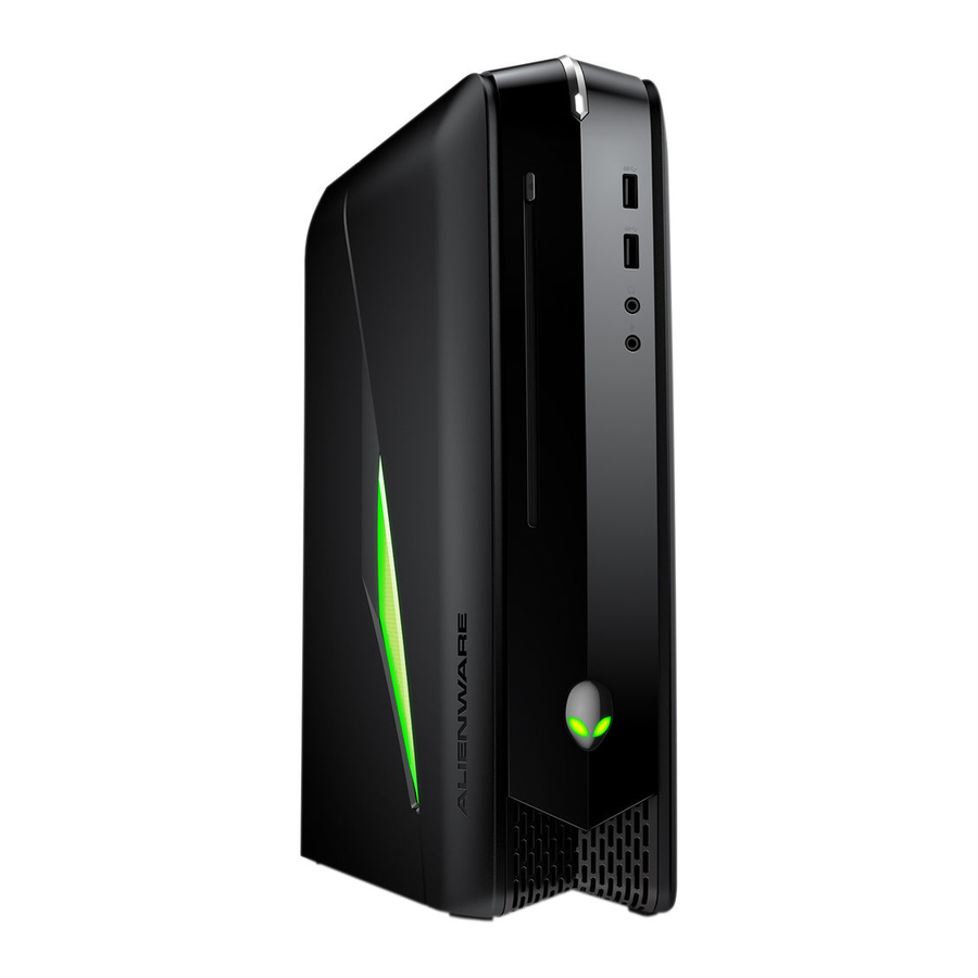
Page 18: Front View Features
Front View Features Alienhead — Lowers the drive panel when pressed. The drive panel can also be lowered when the computer is turned off. Optical drive — Plays or records CDs, DVDs, and Blu-ray Discs Optical-drive bay — Can support additional optical drive. Media Card Reader/Optical-drive bay —... -
Page 19: Back View Features
Back View Features Security cable slot — Attaches a commercially available security cable to the computer. NOTE: Before you buy a security cable, ensure that it fits into the security cable slot on your computer. Latch — Closes or opens the security cable slot and locks or unlocks the release panel. - Page 20 Back Light Button Press the back light button to turn on the light to view the back panel connectors. This light automatically turns off after a few seconds. CHAPTER 2: GETTING TO KNOW YOUR DESKTOP...
-
Page 21: Back Panel Connectors
Back Panel Connectors Optical S/PDIF connector — Connects to amplifiers, speakers, or TVs for digital audio output through optical digital cables. This format carries an audio signal without going through an analog audio conversion process. eSATA connector — Connects to eSATA compatible storage devices such as external hard drives or optical drives. -
Page 22: Connecting External Speakers
Connecting External Speakers Side L/R surround connector — Connects to side L/R surround speakers. Your Alienware desktop has five integrated audio out connectors and one audio in connector. The audio out connectors deliver quality sound and support Rear L/R surround connector —... -
Page 23: Top View Features
Top View Features Accessing the Top Panel Connectors Press the top panel downwards to access the top panel connectors. Top panel CHAPTER 2: GETTING TO KNOW YOUR DESKTOP... - Page 24 Top Panel Connectors Headphone connector — Connects to headphones. NOTE: To connect to a powered speaker or sound system, use the audio out connector or one of the S/PDIF connectors at the back of your computer. Microphone connector — Connects to a microphone or inputs signal for use with audio programs.
-
Page 25: Chapter 3: Using Your Desktop
CHAPTER 4: USING YOUR DESKTOP CHAPTER 3: USING YOUR DESKTOP CHAPTER 3: USING YOUR DESKTOP... -
Page 26: Alienware Command Center
Alienware Command Center Working With RAID The Alienware Command Center gives you access to Alienware’ s exclusive A Redundant Array of Independent Disks (RAID) is a disk storage configuration software and is a continuously upgradable control panel. As Alienware releases that increases performance or data redundancy. - Page 27 RAID Level 0 RAID Level 1 CAUTION: RAID level 0 provides no redundancy. Therefore, a failure RAID level 1 uses data mirroring to enhance data integrity. When data is written of one drive results in the loss of all data. Perform regular backups to to the primary drive, the data is also duplicated, or mirrored, on the secondary protect your data.
-
Page 28: Optimizing Performance
Optimizing Performance Configuring the BIOS Your computer has been configured to operate optimally across a wide range of applications. Depending on the configuration you purchased, the computer System Setup may have been overclocked at the factory to achieve maximum performance in resource intensive applications including gaming and multimedia development. -
Page 29: Product Information
To avoid possible keyboard failure, press and NOTE: For the updated system setup information, see the Service Manual at support.dell.com/manuals. release <F2> in even intervals until the System Setup screen appears. While the desktop is booting, press <F2> immediately before the operating system logo appears to access the BIOS Setup Utility. - Page 30 Main Advanced — Standard CMOS Features CPU Information SATA Port3 Displays the SATA 3 drive integrated in the computer. CPU Type Displays the processor type. SATA Port4 Displays the SATA 4 drive integrated in the CPU ID Displays the processor identification code. computer.
- Page 31 Advanced — CPU Configuration Advanced — Integrated Devices Hyper-threading Jmicron 362 ATA If disabled only one thread per enabled core is Allows you to enable or disable the ATA Controller Technology active. controller. XD Bit Capability ICH SATA Configuration Enable XD Bit Capability to allow the processor to distinguish between the bits of code that SATA Mode Allows you to configure the integrated hard...
- Page 32 Advanced — Frequency/Voltage Control Advanced — ME Subsystem Advance DRAM Execute MEBx Allows you to access the Advance DRAM Allows you to enable or disable the Execute Configuration Configuration submenu. MEBx. Overclock Configuration Allows you to access the Overclock Integrated Clock Chip Allows you to access the Integrated Clock Chip Configuration Configuration submenu.
- Page 33 Advance DRAM Configuration Submenu Overclock Configuration Submenu tRCD Turbo Mode Displays timing of RAS to CAS delay (editable If enabled, allows processor to run at faster in Manual Mode). frequencies than marked. Long duration power Displays timing of RAS Precharge (editable in Allows you to change the long duration limit Manual Mode).
- Page 34 Overvoltage Configuration Submenu Boot DDR3 Memory Voltage Set Boot Priority Adjusts the DDR3 Memory Voltage. 1st Boot Device Dynamic CPU VCore Offset Displays the first boot device. Allows you to change the Processor Core Voltage Offset value. 2nd Boot Device Displays the second boot device.
-
Page 35: Chapter 4: Installing Additional Or Replacement Components
CHAPTER 4: INSTALLING ADDITIONAL NOTE: See the Service Manual at support.dell.com/manuals for installation instructions of all serviceable components. Parts purchased OR REPLACEMENT COMPONENTS from Dell and Alienware ship with specific replacement instructions. CHAPTER 4: INSTALLING ADDITIONAL OR REPLACEMENT COMPONENTS... -
Page 36: Before You Begin
8 to 10 seconds until the desktop turns off. The procedures in this section may require the following tools: • Small flat-blade screwdriver • Phillips screwdriver support.dell.com • BIOS executable update program available at CHAPTER 4: INSTALLING ADDITIONAL OR REPLACEMENT COMPONENTS... - Page 37 Ensure that the work surface is flat and clean to prevent the side panel from CAUTION: Only a certified service technician should perform repairs on being scratched. your desktop. Damage due to servicing that is not authorized by Dell is Turn off your desktop (see “Turning Off Your Desktop” on page 34).
-
Page 38: Removing And Replacing The Side Panel
Removing and Replacing the Side Panel CAUTION: Before removing the side panel, disconnect the power cable from your desktop. To remove the side panel: Follow the instructions in “Before You Begin” on page NOTE: Ensure that you remove the security cable from the security cable slot (if applicable). -
Page 39: Inside View Of Your Computer
Inside View of Your Computer Removing and Replacing Memory Module(s) To remove the memory module(s): Follow the instructions in “Before You Begin” on page Remove the side panel (see “Removing and Replacing the Side Panel“ on page 36). Locate the memory module connectors on the system board (see “Inside View of Your Computer“... - Page 40 To replace memory module(s): Follow the instructions in “Before You Begin” on page Align the notch on the bottom of the memory module with the tab on the memory module connector. Recommended memory configuration: memory module connector notch memory module Type Slots 1333 MHz, 1600 MHz, and 1866 MHz...
-
Page 41: Removing And Replacing Hard Drive(S)
Insert the memory module into the memory module connector until the Removing and Replacing Hard Drive(s) memory module snaps into position. If you insert the memory module correctly, the securing clips snap into the NOTE: For maximum performance of hard drive(s), connect the SATA 3.0 cutouts at each end of the memory module. - Page 42 power cable data cable Press the release tabs together and slide the hard drive out of the hard drive cage. hard drive 2 release tabs (2) Remove the hard drive out of the hard-drive bracket (if applicable). CHAPTER 4: INSTALLING ADDITIONAL OR REPLACEMENT COMPONENTS...
- Page 43 To replace a hard drive: Follow the instructions in “Before You Begin” on page See the documentation that shipped with your new hard drive to verify that it is configured for your computer. Snap the new hard-drive bracket on to the new hard drive (if applicable). Slide the new hard drive into the hard-drive cage until the release tabs snap into place.
-
Page 44: Removing And Replacing Expansion Card(S)
Locate the expansion card on the system board (see “Inside View of Your Removing and Replacing Expansion Card(s) Computer“ on page 37). To remove a card: Disconnect any cables connected to the card (if applicable). Follow the instructions in “Before You Begin” on page Remove the screw that secures the card to the chassis. - Page 45 To replace a card: Connect any cables that should be attached to the card (if applicable). For information about the card’ s cable connections, see the documentation Follow the instructions in “Before You Begin” on page that shipped with the card. Remove the filler bracket to create a card-slot opening (if applicable).
- Page 46 CHAPTER 4: INSTALLING ADDITIONAL OR REPLACEMENT COMPONENTS...
-
Page 47: Chapter 5: Troubleshooting
CHAPTER 6: TROUBLESHOOTING CHAPTER 5: TROUBLESHOOTING CHAPTER 5: TROUBLESHOOTING... -
Page 48: Basic Hints And Tips
When troubleshooting your computer, remember the following safety guidelines: Basic Hints and Tips • Before touching any of the computer’ s internal components, touch an • The computer does not turn on: Is your computer securely plugged into a unpainted portion of the chassis. Doing so will safely discharge any static working electrical outlet? If plugged into a power strip, ensure that the strip electricity, which could damage your computer. -
Page 49: Software Diagnostic Tools
Turn on (or restart) your desktop. When you press <n>, the following message appears on the screen. When the Alienware logo appears, press <F12> immediately to access the “Booting Dell Diagnostic Utility Partition. Press any key to Boot Menu. continue.”... - Page 50 NOTE: Write down any error codes and problem descriptions exactly as also download the latest drivers and software for your computer from they appear and follow the instructions on the screen. support.dell.com. After all tests have completed, close the test window to return to the Alienware Diagnostics Main Menu.
-
Page 51: Troubleshooting
Possible motherboard failure — Chipset error Alienware (see “CONTACTING ALIENWARE“ on page 65). Four RAM read/write failure NOTE: To replace parts, see the Service Manual at Five Real Time Clock failure support.dell.com/manuals. Video card or chip failure Seven Processor failure CHAPTER 5: TROUBLESHOOTING... - Page 52 The computer stops responding or a solid blue screen appears A program is designed for an earlier version of Microsoft Windows CAUTION: You might lose data if you are unable to perform an operating Run the Program Compatibility Wizard: system shutdown. The Program Compatibility Wizard configures a program so that it runs in an If you are unable to get a response by pressing a key on your keyboard or moving environment similar to non-Windows operating system environment.
- Page 53 Check the software documentation or contact the software manufacturer for Other software problems troubleshooting information: Back up your files immediately • Ensure that the program is compatible with the operating system installed on your computer. Use a virus-scanning program to check the hard drive, or CDs •...
- Page 54 Hard Drive Problems Memory NOTE: For maximum performance of hard drive(s), connect the SATA 3.0 Memory errors detected on start up (6Gb/s) compatible hard drive(s) to the SATA 3.0 (6Gb/s) port(s) on the • Check memory modules for correct seating and orientation. Reseat the system board.
- Page 55 Power USB Devices NOTE: For maximum performance of USB device(s), connect USB 3.0 When you press the power button, the computer does not turn on compatible USB device(s) to the USB 3.0 port(s) on your computer. • If the computer is connected into a surge protector or UPS, ensure that the surge protector or UPS is securely connected to an electrical outlet, is USB keyboard or mouse is not responding when connected to USB 3.0 switched on and is working correctly.
- Page 56 CHAPTER 5: TROUBLESHOOTING...
-
Page 57: Chapter 6: System Recovery
— Some of the software that is pre-installed on your computer does not include a backup CD/DVD. This software is available at My Dell Downloads (DownloadStore.dell.com/media). NOTE: My Dell Downloads may not be available in all regions. CHAPTER 6: SYSTEM RECOVERY... -
Page 58: Alienrespawn
Options menu and follow the instructions on the screen. NOTE: The restoration process may take an hour or more depending on the size of the data to be restored. NOTE: For more information on AlienRespawn, see knowledge base article 353560 at support.dell.com. CHAPTER 6: SYSTEM RECOVERY... -
Page 59: Dell Datasafe Online Backup (Optional)
Upgrading to AlienRespawn Professional Dell DataSafe Online Backup (Optional) AlienRespawn provides additional features that allow you to: NOTE: Dell DataSafe Online Backup may not be available in all regions. • Backup and restore your computer based on file types •... - Page 60 CHAPTER 6: SYSTEM RECOVERY...
-
Page 61: Chapter 7: Specifications
CHAPTER 8: SPECIFICATIONS This chapter provides specifications of your desktop. CHAPTER 7: SPECIFICATIONS CHAPTER 7: SPECIFICATIONS... - Page 62 Processor and System Chipset Computer Model Alienware Aurora-R3 Processor Intel Core i7 Intel Core i5 Dimensions Intel Core i3 Height 432 mm (17 inches) L2 cache 256 KB (with top vents open) L3 cache up to 8 MB Width 249 mm (9.8 inches) System chipset Intel P67 Depth...
- Page 63 Memory Top Panel Connectors Connectors four internally-accessible DDR3 DIMM sockets one 4-pin USB 3.0-compliant connector Capacities 1 GB, 2 GB, and 4 GB two 4-pin USB 2.0-compliant connectors 1333 MHz, 1600 MHz, and 1866 MHz Audio one stereo headphone and microphone connectors Minimum 3 GB...
- Page 64 Expansion Bus Computer Environment PCI Express x1: Temperature ranges: Connectors Operating 10°C to 35°C (50°F to 95°F) Connector size 36-pin connectors Storage –10°C to 45°C (14°F to 113°F) PCI Express x16: Relative humidity (maximum) 20% to 80% (noncondensing) Connectors Maximum vibration (using a random-vibration spectrum that simulates user environment): Connector size 164 pins connectors...
-
Page 65: Appendix A: General And Electrical Safety Precautions
APPENDIX A: GENERAL AND ELECTRICAL Computer Use • Route the power cable and all cables away from where people might walk or SAFETY PRECAUTIONS trip over them. Do not allow anything to rest on the power cable. • Do not spill anything on or into your computer. •... - Page 66 General Safety Precautions • Mechanical Shock: Your computer should never be subjected to severe mechanical shocks. Careless handling of your computer may cause damage. Mechanical Shock is not covered by the warranty. • Electrical Shock: If you do not open up your computer, there is nothing to worry about.
-
Page 67: Appendix B: Contacting Alienware
For customers in the United States/Canada, call 1-800-ALIENWARE. • www.dell.com NOTE: If you do not have an active Internet connection, you can find contact information on your purchase invoice, packing slip, bill, or Dell • www.dell.com/ap (Asian/Pacific countries only) product catalog. - Page 68 The following information is provided in the device(s) described in this document in accordance with the requirements of the Official Mexican Standard (NOM): Importer: Dell México S.A. de C.V. Paseo de la Reforma 2620 - Flat 11° Col. Lomas Altas 11950 México, D.F.