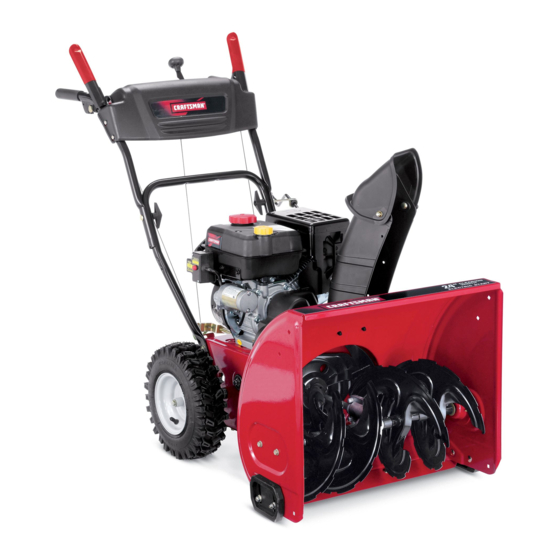
Craftsman 247.889571 Operator's Manual
24" snow thrower
Hide thumbs
Also See for 247.889571:
- Operator's manual (68 pages) ,
- Operator's manual (12 pages) ,
- Operator's manual (76 pages)
Table of Contents
Advertisement
Available languages
Available languages
Operator's
Manual
CRRFTSMRN
24" SNOW THROWER
Model No. 247.889571
CAUTION:
Before
using
this product,
read this
manual
and follow
all
safety
rules
and operating
instructions.
o SAFETY
ASSEMBLY
OPERATION
MAINTENANCE
PARTS LIST
o ESPANOL
Sears Brands
Management
Corporation,
Hoffman
Estates,
IL 60179, U.S.A.
Visit our website:
www.craftsman.com
FORM1/0. 769-05095D
7/26/2011
Advertisement
Table of Contents

Related Manuals for Craftsman 247.889571


Summary of Contents for Craftsman 247.889571
- Page 1 Operator's Manual CRRFTSMRN 24" SNOW THROWER Model No. 247.889571 o SAFETY ASSEMBLY OPERATION MAINTENANCE PARTS LIST CAUTION: Before using o ESPANOL this product, read this manual and follow safety rules and operating instructions. Sears Brands Management Corporation, Hoffman Estates, IL 60179, U.S.A. Visit our website: www.craftsman.com FORM1/0.
- Page 2 Warranty S tatement ....Page2 Off-Season S torage....Page24 SafeOperation P ractices ....Pages 3-6 Troubleshooting ...... Page25 Assembly ......Pages 8-11 PartsList......Pages 26-42 Operation ......Pages 12-15 Repair P rotection A greement .... Page47 Service &Maintenance ....Pages 16-23 Espa_ol ......
- Page 3 This machinewas builtto be operatedaccordingto the safeopera- This symbolpointsout importantsafetyinstructionswhich,if not tion practicesin this manual.As with anytype of powerequipment, followed,couldendangerthepersonalsafetyand/orpropertyof carelessnessor error on the partof the operatorcan resultin serious yourselfand others. Readand followall instructionsin this manual injury.This machineis capableof amputatingfingers,hands,toes beforeattemptingto operatethis machine.Failureto complywith and feet and throwingdebris.Failureto observethe followingsafety these instructionsmay resultin personalinjury.Whenyou seethis...
- Page 4 Safe Handling of Gasoline • Exerciseextremecautionwhenoperatingon or crossinggravel surfaces.Stay alertfor hidden hazardsor traffic. Toavoidpersonalinjuryor propertydamageuseextremecare in handlinggasoline.Gasolineis extremelyflammableand the vaporsare • Exercisecautionwhenchangingdirectionand whileoperatingon explosive.Seriouspersonalinjurycan occurwhengasolineis spilled slopes.Do notoperateon steep slopes. on yourselfor yourclotheswhichcan ignite.Washyour skin and • Planyoursnow-throwing patternto avoiddischargetowards changeclothesimmediately.
- Page 5 MAINTENANCE & STORAGE DO NOT MODIFY ENGINE • Nevertamperwith safetydevices.Checktheirproperoperation Toavoidseriousinjuryor death,do not modifyengine in any way. regularly.Referto the maintenance and adjustmentsectionsof Tampering with the governorsettingcanlead to a runawayengineand this manual. cause it to operateat unsafespeeds.Nevertamperwithfactory setting of engine governor. •...
- Page 6 SAFETY SYMBOLS This pagedepictsand describessafetysymbolsthat mayappear on this product. Read,understand,and followall instructionson the machine beforeattemptingto assembleand operate. READ THE OPERATOR'S MANUAL(S) Read, understand, and follow all instructions in the manual(s) before attempting to assemble operate WARNING-- ROTATING BLADES Keep hands out of inlet and discharge openings while machine is running.
- Page 7 Thispage leftintentionally blank.
- Page 8 NOTE:References to rightor left sideof the snowthrowerare determined from behindthe unit in the operatingposition(standing directlybehindthe snow thrower,facingthe handlepanel). REMOVING FROM CARTON Cut the cornersof thecarton and lay the sidesflat on the ground. Removeand discard all packinginserts. Movethe snowthrowerout of thecarton. Makecertainthe carton has beencompletelyemptiedbefore discardingit.
- Page 9 Positionthechute assemblyoverthe base.See Figure3. Closethe flangekeepersto securethechute assemblyto the chute base.See Figure4. The flangekeeperswill click intoplace whenproperlysecure. NOTE:If the flangekeeperswill noteasily clickinto place,usethe palmof yourhand to applyswift,firm pressureto the backof each. Removetheflat washerand hairpinclip from the end of the chutedirectionalcontrol. Insertthe end of the chutedirectionalcontrolinto the lower bracketand securewith the flat washerand hairpinclipjust removed.See Figure5.
- Page 10 SET-UP Chute Clean-Out Tool A chute clean-out tool is fastenedto the top of the augerhousing with a mountingclip. See Figure6. The tool is designedto cleara chuteassemblyof ice and snow.This item is fastenedwith a cabletie at the factory.Cut thecable tie beforeoperatingthe snowthrower. ChuteClean-outTool Neveruseyour handsto cleara cloggedchuteassembly.Shut off engineand remainbehind handlesuntilall movingpartshave...
- Page 11 Makecertain theentirebottomsurfaceof skid shoeis againstthe groundto avoidunevenwearon the skid shoes, ..Refightennutsand bolts securely, Chute Assembly Thedistancesnowis throwncan be adjustedby changingthe angle of the chuteassembly,Todo so: Stopthe engineby removingthe ignitionkeyand loosenthe plasticwingknobfoundon the left sideof the chuteassembly. Pivotthe chute upwardor downwardbeforeretightening thewing knob,See Figure8, Auger Control...
- Page 12 Shift Lever Drive Control Auger Control Gas Cap ChuteAssembly Oil Fill ChuteDirectionalControl Clean Out Mumer Recoil Starter Tool _.Handle Primer Throttle Control Choke Control :lectric Start Augers Button Oil Drain Skid Shoe Electric Starter Outlet Figure10 Nowthat youhaveset up yoursnowthrower,it'simportant to become acquainted with itscontrolsand features.Referto Figure10.
- Page 13 THROTTLE CONTROL The augercontrol is locatedon the left handle.Squeezethe control grip againstthe handleto engagethe augerand startsnowthrowing action.Releaseto stop. DRIVE CONTROL/AUGER CONTROL LOCK aiW' DRIVE CONTROL Thethrottlecontrolis locatedon the rearof the engine.It regulatesthe speedof theengine and will shutoff the enginewhenmovedintothe OFF position. Depressingthe primerforcesfuel directlyinto ___144 the engine'scarburet°rt°...
- Page 14 CLEAN-OUT TOOL • Refuelin a well-ventilated area with the enginestopped.Do not smokeor allowflamesor sparksin the areawherethe engineis refueledor wheregasolineisstored. Neveruse yourhandsto cleara cloggedchute assembly.Shut • Donot overfillthe fueltank.After refueling,makesurethe tank off engineand remainbehindhandlesuntilall movingpartshave cap is closed properlyand securely. stoppedbeforeusingthe clean-outtoolto clear thechute assembly. •...
- Page 15 TO ENGAGE DRIVE Movethrottlecontrolto FAST(rabbit)_T position. With the throttlecontrolin the Fast(rabbit) '_ position,move Movechoketo the CHOKE IJl position(coldenginestart). If shiftleverintoone of thesix forward(F) positionsor two reverse engineis warm,placechokein RUNposition. (R) positions.Selecta speedappropriatefor the snowconditions Pushprimerthree (3) times, makingsureto covervent hole in and a paceyou'recomfortable with.
- Page 16 MAINTENANCE SCHEDULE Before performing anytype ofmaintenance/service, disengage all Followthe maintenance schedulegiven below.This chart describes controls and stoptheengine. W aituntilall moving partshavecometo serviceguidelinesonly. Usethe ServiceLog columnto keeptrackof a completestop.Disconnect sparkplugwireandgroundit against t he completedmaintenance tasks.To locate the nearest Sears Service enginetoprevent u nintended starting. A lwayswearsafety glassesduring Centeror to scheduleservice,simplycontactSearsat 1-800-4-MY-HOME®.
- Page 17 Reinstallthe drain plugand tightenit securely. Refillwith the recommended oil and checkthe oil level.See Recommended Oil Usagechart.Theengine'soil capacityis 20 ounces. (%-400 -200 0o 200 400 Oil Drain ("c) -300 -200 -10° 0° Plug DONOTuse nondetergent o il or 2-strokeengineoil. It could shorten the engine'sservicelife.
- Page 18 become hot a nd can inc. LUBRICATION Gear Shaft Thegear (hex)shaft shouldbe lubricatedat least oncea seasonor afterevery 25 hoursof operation. Topreventspillage,removeall fuel fromtank by runningengine until it stops. Carefullypivotthe snowthrowerup and forwardso that it restson theauger housing. Removethe lowerframecover fromthe undersideof the snow throwerby removing the self-tappingscrewswhich secureit.
- Page 19 ADJUSTMENTS Shift Cable If thefull rangeof speeds(forwardand reverse)cannotbe achieved, referto the figureto the rightand adjustthe shift cableas follows: Placethe shiftleverin thefastest forward speedposition(F6). Loosenthe hex nuton the shiftcable indexbracket.See Figure Pivotthe bracketdownwardto take up slack in the cable. Retightenthehex nut. Drive Control Whenthedrivecontrol is releasedand in thedisengaged"up"position, the cableshouldhavevery little slack.It shouldNOTbe tight.
- Page 20 Auger Control "_ Referto the Assemblysectionfor instructions on adjustingtheauger controlcable. Skid Shoes Referto the Assemblysectionfor instructions on adjustingthe skid shoes. BELT REPLACEMENT Auger Belt To removeand replaceyoursnow thrower'sauger belt, proceedas follows: Topreventspillage,removeall fuel fromtank by runningengine until itstops. Removethe plasticbelt coveron the front of the engineby remov- ing the two self-tappingscrews.See Figure22.
- Page 21 6. Remove the belt a sfollows. Refer toFigure 25. a. Loosen and remove the shoulder screw w hich a cts a sabelt keeper. b. Unhook the auger brake b racket spring from the frame. 7. Remove the belt f rom around the auger pulley, and slip the belt between thesupport bracket and the auger pulley.
- Page 22 4, Carefully pivot the snow thrower upand forward so that i trests o n the auger housing. 5. Remove the frame c over from the underside ofthe snow thrower byremoving the self-tapping screws which s ecure it.Refer to Figure 24, 6.
- Page 23 NOTE:Be carefulnot to damagethe threadson the shaft, Carefullypositionthe hexshaftdownwardand to the left before carefullyslidingthe frictionwheelassemblyoff the shaft. See Figure31. NOTE: If you'rereplacingthe frictionwheelassemblyas a whole, discardthe wornpartand slidethe newpart ontothe hexshaft. Followthe stepsabovein reverseorderto reassemble components. Performthetest previouslydescribedin the Drive Control section.
- Page 24 If the snowthrowerwillnot be usedfor30 daysor longer,or if it is the end of the snowseasonwhenthe last possibilityof snowis gone,the equipmentneedsto be storedproperly.Followstorageinstructionsbelowto ensuretop performance from the snowthrowerfor manymoreyears. PREPARING SNOW THROWER PREPARING ENGINE Whenstoringthe snowthrowerin an unventilatedor metal stor- Enginesstoredover30 days need to be drainedof fuel to prevent age shed,careshouldbe taken to rustprooftheequipment.Using deterioration and gumfrom formingin fuel systemor on essential a light oil or silicone,coat theequipment,especiallyanychains,...
- Page 25 Enginefails to start Chokecontrolnot in CHOKEposition. Movechokecontrolto CHOKEposition. Sparkplugwire disconnected. Connectwireto sparkplug. Faultysparkplug. Clean,adjustgap,or replace. Fueltank emptyor stalefuel. Filltank with clean,freshgasoline. Enginenot primed. Primeengineas instructedin the OperationSection. Keynot inserted. Insertkeyfully intothe switch. Connectone end of the extensioncordto the electric Extensioncordnot connected(when usingelectricstartbutton,on modelsso starteroutletand the otherend to a three-prong equipped).
- Page 26 Craftsman Snow Thrower IViodel 247.889571 ///'...
- Page 27 Craftsman Snow Thrower IViodel 247.889571 731-2635 SnowRemoval T oolMount 684-04107-0637 SpiralAssembly,LH 684-04057A-0637 ImpellerAssembly,12"Dia. 684-04108-0637 SpiralAssembly,RH 710-0347 HexScrew,3/8-16, 1.75,Gr5 731-04870 Spacer,1.25OD x .75 ID x 1.00 710-0451 Bolt,Carriage,5/16-18,.750Grl 736-0188 Washer,Flat, .76x 1.49x .06 710-04484 Screw, 5/16-18, 0 .750 741-0493A Bushing,Flange,.80 ID x .91OD 710-0703 Screw,Carriage,1/4-20,.750,Gr5 790-00087A-0637 Housing,1"Hex Bearing...
- Page 28 Craftsman Snow Thrower Model 247.889571 y:,15,1 _4_,...
- Page 29 Craftsman Snow Thrower IViodel 247.889571 " 731-04869A Chute,FlangeKeeper 631-04133A HandleAssembly,ClutchLock,LH 946-04397A Cable,SpeedSelector 631-04134B HandleAssembly,ClutchLock,RH 749-04191A-0637 Handle,Upper,LH 684-04111B HandleAss'y,Engage,Red, LH 747-04263 EyeBolt, ChuteCrank 684-04112B HandleAss'y,Engage,Red, RH 790-00313-0637 Shift Lever J 631-04131B J Chute,Lower(/ncl_Ref_#27,Qty. 3) 731-04912B Chute,Lower,5.0 Dia. 732-04238 Spring,Torsion,.8156ID x .3038 914-0145 ClickPin 710-0276...
- Page 30 Craftsman Snow Thrower IViodel 247.889571...
- Page 31 Craftsman Snow Thrower IViodel 247.889571 656-04055 DiscAssembly,FrictionWheel 731-04873 Spacer,1.25x .75x 3.0 938-04168 Axle, .75x 22" 684-04153 FrictionWheelAssembly,5.50D 736-0329 Washer,Lock, 1/4 684-04154B-0637 SupportBracket,FrictionWheel 684-04156A Shift Assembly,Rod 710-0809 Hex Screw,1/4-20,1.25,Gr5 710-0191 Hex Screw,3/8-24, 1.25,Gr8 J 710-0627 J HexScrew,5/16-24,.750,Gr5 710-0788 Screw,1/4-20,1.000 710-0672 Hex Screw,5/16-24,1.25,Gr5 710-1652 Screw,1/4-20x .625 710-0654A...
- Page 32 Craftsman Engine Model 265=SU-11 For Snow Model 247.889571 1121 710-04914 Bolt M6xlO 951-11680 i 122 WireClip i 123 951-11114 SwitchHousingMountingBracket i 124 712-04212 Nut M6 i 125 710-04965 Bolt M4x55 i 126 710-04935 Bolt M4x60 i 127 710-05182 Bolt M6x32 i 128 715-04088 DowelPin 8x8...
- Page 33 Craftsman Engine IViodel 265=SU=11 For Snow IViodel 247.889571 710-04939 Stud M6x117 MixtureScrew 710-04910 Stud M6x105 951-11699 PrimerHose 951-11567 CarburetorInsulatorGasket 951-11906 HoseClamp 951-11896 CarburetorInsulator Carburetor Body 951-11569A CarburetorGasket FloatPin 951-10639A EmulsionTube PrimerAssembly 951-11824 PrimerBulb NeedleValve 951-10974A MainJet CarburetorAssembly 951-11897 CarburetorGasketPlate NeedleValveSpring ChokeShaft Float Choke Plate...
- Page 34 Craftsman Engine IViodel 265=SU=11 For Snow IViodel 247.889571...
- Page 35 Craftsman Engine IViodel 265-SU-11 For Snow IViodel 247.889571 951-11283 951-11688 Oil Fill PlugAssembly PistonRingSet 951-11577 951-11632 O-Ring15.8x2.5 PistonPin Snap Ring 951-11368 Oil Seal 25x41.25x6 951-11900 Piston 951-11248A Crankcase Kit 951-11901 PistonPin 710-04915 BoltM6x12 (Incl.61,64,76,77,79) 951-11350 951-11113 Air Shield Oil DrainPipeAssy. 736-04440 Washer 10x16x1.5 951-11573...
- Page 36 Craftsman Engine IViodel 265=SU=11 For Snow IViodel 247.889571...
- Page 37 Craftsman Engine IViodel 265=SU=11 For Snow IViodel 247.889571 951-10292 710-04744 BoltM6x16 SparkPlug/F6Rtc 951-11898 951-11054 ValveCover Gasket,CylinderHead 951-10648 PushRodKit 731-07059 BreatherHose 951-11899 726-04101 Tappet HoseClamp 715-04090 951-11565 ValveCoverGasket DowelPin,10x16 951-10647A ValveKit 951-12000 Retainer,In.ValveSpring 951-10647A ValveKit 951-11892 RockerArmAssembly 951-11063A ValveCoverKit 751-11124 Nut,Pivot Locking 952Z265-SU-11 751-11123 CompleteEngine...
- Page 38 Craftsman Engine IViodel 265=SU=11 For Snow IViodel 247.889571 951-10646 IgnitionCoil Assembly 951-11110 Air FlowShield 710-04940 BoltM6xlO 710-04919 BoltM6x25 951-12416 Flywheel 951-10909 Fan,Cooling 951-10911 Pulley,Starter 712-04209 Nut,Special?M14x1.5 710-04915 BoltM6x12 951-10663A BlowerHousing 736-04455 Gasket6 710-04974 BoltM6xlO 951-10658 RecoilStarter 731-05696 RecoilStarterHandle 710-04979 BoltM6x18 951-11109 BlowerHousingShield...
- Page 39 Craftsman Engine Model 265=SU-11 For Snow Model 247.889571 112-% t/ z 111 951-10758 PrimerBracket 710-04915 Bolt M6x12 710-04928 BoltM6x12 951-10662 DipstickDecorationCover 951-11108 710-04905 Bolt GovernorSystemShield 951-11935 710-04915 Bolt M6x12 GovernorSpring 951-10664 951-11381 ThrottleLinkageSpring Oil FillTubeO-Ring 951-10665 951-11913 ThrottleLinkage Oil FillTubeAssembly 951-11106 GovernorArm 951-11904...
- Page 40 Craftsman Engine IViodel 265=SU=11 For Snow IViodel 247.889571 951-11112 ChokeControl 951-11282 MufflerAssembly 951-10634 710-04911 MufflerStud M8x36 Air CleanerHousing 951-10657 712-04213 MufflerStudAssembly 951-11285 Muffler Gasket 951-11284 ChokeKnob 951-10757 ThrottleControlKnob 712-04214 Nut,M8 951-10637 951-11111 ExhaustPipe Shield KeySwitch 710-04914 BoltM6xlO 731-05632 710-04915 BoltM6x12 951-10640 Choke PushRod 951-10635...
- Page 41 Craftsman Engine Model 265=SU-11 For Snow Model 247.889571 777533610 777U22991 777J22992...
- Page 42 Craftsman Snow Thrower Niodel 247.889571 777S32636 777X43688 "1001IAO-NV:r'IO "'IVnNVlNS,I:IOLVEI3clO OV3U"S "S30VJEInS 3 3AVEI9 NO9NIIVEI3dO 3sn "SU]ONVS.SX8 NOIlnVo VEIIX3 N3HM :IOEIVHOSIO 103910 EI3A::IH 'S31EInI'NI S.LO3rso NMOEIHI O IOAV O/"'17 "3NIHOVIt,] 9NIOIAEFIS E IO9NI990IONn 3E10-138 O3clclO.LS 3AVH SIEIVd9NIAOIN llP II.LNnS:IIONVH ONIH38 N IVIN3EI ONV'3NIgN3 dO.L$ ' SEI3A3I HO.l.n]o : 19¥9N3$10 "£ "31flHO 39EIVHO$10 90lONn 01 1001 IAO-NV3"IO 3 $fl "g "133::10NV SONVH :I.LVIndWV NVO EFIgnv E IO EIq'l13dlNI HIIM...
- Page 44 MTD. OWNER'S WARRANTY RESPONSIBILITIES: As the smalloff-roadengineowner,youare responsible forthe performance of the requiredmaintenance listed in your Owner'sManual.MTD recommends that you retainall yourreceiptscoveringmaintenances on yoursmalloff-roadengine,but MTDcan not denywarrantysolelyfor the lack of receiptsor foryour failureto ensurethe performanceto all scheduledmaintenance. As the smalloff-roadengineowner,youshouldhoweverbe awarethat MTDmaydenyyour warrantycoverageif yoursmall off-roadengine or part hasfaileddue toabuse, neglect,impropermaintenance or unapprovedmodifications.
- Page 45 (8)Throughout the engine's warranty period defined inSubsection (a)(2), MTD will m aintain a supply ofwarranted parts s ufficient tomeet the expected demand forsuch parts. (9)Any replacement part m ay b eused i ntheperformance...
- Page 46 Look For Relevant Emissions Durability Period and Air index information On Your Engine Emissions Label Engines that are certified to meet the California Air Resources Board (CARB) Tier 2 Emission Standards must display information regarding the Emissions Durability Period and the Air Index. Sears Brands Management Corporation makes this information available to the consumer on our emission...
- Page 47 Congratulations on making a smart purchase. Your new Craftsman® product is designed manufactured for years of dependable operation. But like all products, it may require repair from time to time. That's when having a Repair Protection Agreement can save you money and aggravation.
- Page 48 Declaraci6n de garantia ......Pagina 48 Soluci6n de problemas ......Pagina 70 Practicas operaci6n seguras ..... Pagina 49 Acuerdo de protecci6n para reparaciones ..Pagina 75 Montaje ............Pagina 53 Lista de piezas ........... Pagina 26 Operaci6n ..........Pagina 57 NOmero de servicio ........
- Page 49 Esta rn_.quina r ue construidapara seroperadade acuerdocon La presenciade este sfrnboloindicaque setrata de instrucciones las reglasde seguridadcontenidasen este manual.AI igualque irnportantesde seguridadque se deben respetarpara evitar concualquiertipo de equipo rnotorizado, u n descuidoo error por poner en peligrosu seguridadpersonaly/o materialy la de otras partedel operadorpuedeproducirlesionesgraves.Esta rn_.quina personas.Lea y siga todaslas instruccionesde este manualantes es capazde arnputarrnanosy piesy de arrojarobjetoscon gran...
- Page 50 Manejo seguro de la gasolina • Nuncaoperela rn_.quina si falta un rnontajedel canalo si el rnisrnoest,. daSado.Mantengatodos losdispositivosde seguri- Paraevitar lesiones personales 0 daSosrnateriales tengarnucho dad en su lugaryen funcionarniento. cuidadocuandotrabajecon gasolina.La gasolinaes surnarnente inflarnabley sus vaporespuedencausarexplosiones. S i se derrarna •...
- Page 51 • Paraencenderel motor,jale de la cuerdalentarnente hasta que • SegOn la Cornisi6nde Seguridad de Productosparael Consurni- sienta resistencia,luegojale r_.pidarnente. El replieguer_.pido de dor de los EstadosUnidos(CPSC)y la Agenciade Protecci6n la cuerdade arranque(tensi6nde retroceso)le jalar_,la rnanoy Arnbiental d e los EstadosUnidos(EPA),este productotieneuna el brazohaciael motor rn_.s r_.pido de Io que usted puedesoltar.
- Page 52 SiMBOLOS DE SEGURIDAD Esta p_ginadescribelossimbolosy figurasde seguridadinternacionales que puedenapareceren este producto.Lea el manualdel operador )araobtenerla informaci6n terminadasobreseguridad,reunirse,operaci6ny mantenimiento y reparaci6n. LEA EL MANUAL DEL OPERADOR (S) Lea, entienda, y siga todas las instrucciones en el manual (es) antes de intentar reunirse y funcionar.
- Page 53 NOTA:las referencias al lado derechoo y ciertosde la m_.quina quitanievesedeterminandesdela parteposteriorde la unidaden posici6nde operaci6n(permaneciendo directamente detr_.sde la m_.quina quitanieve,mirandohaciael panelde la manija). EXTRACCI6N DE LA UNIDAD DE LA CAJA Corte lasesquinasde la cajade cart6ny exti_ndalaen el piso Quitey descartetodos los insertosde empaque. Saquela m_.quina quitanievede la caja.
- Page 54 SitOeel montajedel canalsobrela base.Vea la figura3. Cierrelos fijadoresde la bridapara asegurarel montajedel canal a la basedel canal. Veala figura4. Losfijadoresde la brida emiten un chasquidocuandoest_.nbien asegurados. NOTA:si los fijadoresde la brida no seajustanen su lugarf_.cilmente, utilice la palmade su rnanopara apfcar una presi6nr_.pida y firmeen la parteposteriorde cadauno.
- Page 55 CONFIGURACION "_ " Herramienta de Lirnpieza del Canal Hay una herrarnienta de lirnpiezadel canal iajustada a la parte superiorde la caja de la barrenacon un pasadorde ensarnNado.Vea la figura6. La herrarnienta est,. diseSadapara lirnpiarel hieloy la nievedel rnontajede un canal.Este productose sujeta rnedianteuna Herramienta de uni6nde cableen la f_.brica.
- Page 56 Paraajustarlas zapatasantideslizantes: Aflojelascuatrostuercashexagonales (dos en cada lado)y los pernosdel carro.Muevalas zapatasantideslizantes a la posici6n deseada.Vea la figura 7. Cornpruebe que toda la superficieinferiorde laszapatas antideslizantes est_ contrael sueloparaevitar un desgaste desparejode los rnisrnos. Vuelvaa ajustarbien las tuercasy los pernos. Ajuste del montaje del canal Es posibleajustar la distanciaa la cualse arroja la nievecarnbiandoel...
- Page 57 Control de Transmisi6n Palanca de Cambios Controlde la Barrena Tapbn de combustible IVlontaje del canal Llenado de aceite \\ Control direccional del canal Herramienta Manija del arrancador limpieza del canal Sdenciaclor de retroceso Cebador Control del regulador Control del cebador Botbn del el_ctrico arrancador...
- Page 58 CONTROL DEL REGULADOR El controlde la barrenaest,. ubicadoen la manijaizquierda.Apriete la empuSadura de controlcontra la manijapara engranarla barrenay empiecea quitarnieve.Suelteparaque se detenga. CONTROL DE LA TRANSMISION/CONTROL DE LA BARRENA DE CERRADURA El control del regulador estfi ubicado en la parte trasera del motor. Negula la velocidad del motor, y Io apaga cuando se Iocoloca en la S CONTROL DiE LA...
- Page 59 Paracarnbiarla direcci6nhaciala cual se arrojala nieve,gire el NOTA:No Io Ileneen exceso.El Ilenadoexcesivode aceite puede controldireccionaldel canal. hacerque el motorgenerehurno,que cuestearrancarloo fallas en la bujia. HERRAMIENTA DE LllVlPIEZA Vuelvaa colocarel tap6n/la varillade aceitey ajuste confirrneza antes de arrancarel motor. Gasolina Nuncause sus rnanospara liberarun rnontajede canaltapado.Antes Utilicegasolinaparaautorn6viles(sinplornoo conbajo contenidode de destaparlo,apagueel motory perrnanezca detr_.s de las rnanijas I plornopara rninirnizarlosdep6sitosen la c_.rnara de cornbusti6n)con...
- Page 60 Arrancador el_ctrico Muevala palancadel cebadorhastala posici6nCHOKE I,'q¢l (encendidoconel motoren fifo). Si el motorya est,. caliente, ubiqueel cebadoren la posici6nOFR El arrancadorel_ctricoopcionalest&equipadocon un cable de ali- Presioneel cebadortres (3) veces,asegur_.ndose d e cubrirel rnentaci6n y un enchufede tres terrninales conectadosa tierray est,. orificio de ventilaci6ncuandoIo haga.Si el motorest,.
- Page 61 LISTA DE MANTENIMIENTO Antes de realizarcualquiertipo del rnantenirniento/servicio, suelte Siga la lista de rnantenirniento dada abajo.Estacarta describepautas todos los rnandosy pare el motor.Esperehasta quetodas las partes de servicios61o. U sela colurnnade Troncode Serviciopara guardar de rnovirniento hayanvenidoa una paradacornpleta.Desconecteel la pistade tareasde rnantenirniento cornpletadas. L ocalizarel rn_.s alarnbrede bujia y b_.selo contrael motorpara prevenirel cornienzo cercano Charnusca el Centrode Servicioo prograrnar el servicio,sirn- involuntario.
- Page 62 Cambio de aceite del motor NOTA:Carnbieel aceitedespu_sde las 5 prirnerashorasde operaci6ny despu_sde cada50 horasde operaci6no una vez por ternporada. Vacfeel combustibledel tanquehaciendofuncionarel motor hastaque el tanquede combustibleest_ vacfo.Cerci6resede que la tapadel combustibleest,. asegurada. Coloqueun recipiente adecuadopara recolectarel aceitebajo el tap6nde drenajede aceite. Retireel tap6nde drenajede aceite.Vea la Figura12.
- Page 63 Midala separaci6nde bujia con un calibrador.Corrijade ser necesariotorciendoel electrodolateral.Vea la Figura14.La separaci6n debe establecerseentre0,02y 0,03 pulgadas Electrodo (0,60-0,80ram). Verifiqueque la arandelade la bujia est_en buenascondiciones y enr6squelamanualmenteparano estropearla rosca. Unavez que la bujfaest_ colocada,apri_telacon una Ilavepara comprimirla arandela. NOTA:Cuandoinstaieuna bujia nueva,una vez colocadala bujia apriete1/2vuelta paracomprimirla arandela.Cuandovuelvaa co[ocar 0,02= 0,03 puigadas una bujfausada,una vez colocadala bujia apriete1/8- 1/4de vuelta...
- Page 64 PLACA DE RASPADO Y ZAPATAS ANTIDESLIZANTES La placade raspadoy laszapatasantideslizantes ubicadasen la base de la rn_.quina quitanieveest_.n sujetasa desgaste.Peri6dicarnente deberiacontrolarlospernosy reernplazarlos c uandosea necesario. NOTA:Laszapatasde esta rn_.quina t ienendos bordesde desgaste. Cuandoun lado se desgasta,se las puede rotar 1800 para usarel otro horde.
- Page 65 Aflojela tuerca hexagonal i nferiordel soportedel cablede la transmisi6n,Veala figura 19, Ubiquela m6nsulahaciaarribapara brindarm_.s juego (o hacia abajo paraaumentarla tensi6ndel cable). Vuelvaa apretarla tuercahexagonalsuperior, Soporte del canal Si la espiralsituadaen la parteinferiordel controldireccionaldel canal no seenganchacompletamente conel montajedel canal,es posible ajustarel soportedel canal, Parahacerlo: Aflojelas dostuercasque sujetanel soportedel canaly cambie su posici6nligeramente.
- Page 66 Aflojey retireel tornillocon rebordeque actOacomoguarda de la correa.Vea la figura24. Desenganche el resortede la m_nsulade soportedel marco. Retirela correade alrededorde la poleade la barrenay deslice la mismaentre la m_nsulade soportey la polea de la barrena. Vea la figura25. Pararealizarel reensamblado de la correade la barrenasiga las instruccionesen orden inverso.
- Page 67 4. Gire c on cuidado larn_.quina quitanieve hacia a rriba y hacia delante dernanera que quede apoyada sobre l acaja dela barrena. 5. Saque lacubierta del m arco desde d ebajo delarn_.quina quita nieve r etirando los torniNos autorroscantes que la aseguran.
- Page 68 NOTA:Tengacuidadode no daSarlas roscasdel eje. Concuidado,ubiqueel eje hexagonalhaciaabajoy haciala izquierdaantesde deslizarcon precauci6nel rnontajede la rueda de fricci6nfueradel eje.Vea la figura30. NOTA:Cuandosedesea reernplazar e l conjuntode la ruedade fricci6ncornpleto,descartela piezadesgastaday deslicela nueva piezaen el eje hexagonal. Parareensarnblar l os cornponentes siga lospasosanterioresen orden inverso.
- Page 69 Si no sevaa utiliza el equipo durante30 dfaso rn_.s, o sies el finalde la ternporada de nievey ya noexisteposibilidad deque nieve, e s necesario alrnacenar e l equipo de rnanera adecuada. S igalasinstrucciones d e alrnacenarniento quese indicana continuaci6n p aragarantizar e l rendirniento rn_.xirno d e la rn_.quina q uitanieve durante rnuchos a_os.
- Page 70 El motorno arranca La palancade obturaci6nno est,. en la Pongael interruptor en la posici6nCHOKE(obtura- posici6nON (encendido) ci6n). Se ha desconectado el cablede la bujia Conecteel cablea la bujfa. La bujia nofunciona correctamente Limpie,ajustela distanciadisruptivao cambie. El tanquede combustibleest,. vado o el Lleneel tanquecongasolinalimpiay fresca.
- Page 71 Dernasiada vibraci6n Hay piezasque est_.n fiojas o la barrena Detengael motorde inrnediatoy desconecteel est,. dafiada cablede la bujia.Ajuste todoslos pernosy las tuercas.Si la vibraci6ncontinQa. I levela unidada reparara un centrode partesy reparaci6nSears. Perdidade potencia El cable de la bujfaest,. flojo Conectey ajusteel cablede la bujfa.
- Page 72 Subsecci6n(c) debe estar garantizada por un periodode garantiadefinidoen la Subsecci6n(a) (2). Si la piezafalladurante el periodode coberturade la garantia,la mismaser_.reparadao reemplazada por MTD de acuerdocon la Subsecci6n(4) a continuaci6n. Cualquierpiezareparadao reemplazada segQnla garantiasegarantizarB, por el resto del periodode garantia.
- Page 73 (8)Durante todo elperiodo degaranfia del m otor definido enlaSubsecci6n (a) (2),MTD rnantendr_, unsurninistro depiezas cubiertas por garantia suficiente para s atisfacer ladernanda esperada para tales p iezas.
- Page 74 Busque el periodo de duraci6n de emisiones importantes yla informaci6n de clasificaci6n de aire en la etiqueta de emisiones de su motor Los motores cuyo cumpiimiento con los estAndares de emisi6n Tier 2 de la Comisi6n de Recursos Ambientales de California (CARB) est6 certificado deben exhibir la informaci6n relacionada con el periodo de duraci6n de ias emisiones y la clasificaci6n de aire.
- Page 75 Felicitaciones por haber realizado una adquisici6n inteligente. El producto Craftsman® que ha adquirido esta diseSado y fabricado para brindar muchos aSos de funcionamiento confiable. Pero como todos los productos a veces puede requerir de reparaciones. Es en ese momento cuando disponer de un Acuerdo de protecci6n...
- Page 76 Your Home For troubleshooting, product manuals and expert advice: managernylife www.managemylife.com For repair - in your home - of all major brand appliances, lawn and garden equipment, or heating and cooling systems, no matter who made it, no matter who sold it! For the replacement parts, accessories owner's manuals that you need to do-it-yourself.