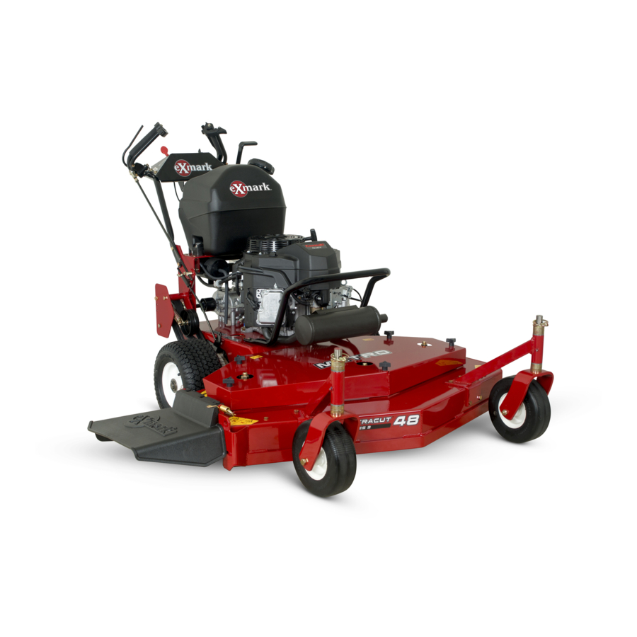
Exmark Metro Operator's Manual
Exmark mower operator's manual metro
Hide thumbs
Also See for Metro:
- Operator's manual (60 pages) ,
- Parts manual (20 pages) ,
- Setup instructions (7 pages)
Table of Contents
Advertisement
Advertisement
Table of Contents
Troubleshooting

Related Manuals for Exmark Metro


Summary of Contents for Exmark Metro
- Page 2 ♦ Keep away from eyes and skin. ♦ Never siphon by mouth. Exmark reserves the right to make changes or add improvements to its products at any time without incurring any obligation to make such changes to products manufactured previously. Exmark, or its distributors and dealers, accept not responsibility for variations which may be evident in the actual specifications of its products and the statements and descriptions contained in this publication.
- Page 3 3. Exmark being unable to ship the part and the Exmark parts order is received by 3:00 p.m., central time, Exmark pays for the part and freight. 4. If the part does not arrive overnight due to the shipper (UPS), the shipper pays for the freight and Exmark pays for the part.
- Page 4 If additional information is needed, or should you require trained mechanic service, contact your authorized Exmark equipment dealer or distributor. All Exmark equipment dealers and distributors are kept informed of the latest methods of servicing and are equipped to provide prompt and efficient service in the field or at their service stations.
-
Page 5: Table Of Contents
1. SAFETY 1.1 Safety Alert Symbol ... 1 1.2 Training ... 1 1.3 Preparation... 1-3 1.4 Operation ... 3-4 1.5 Maintenance & Storage ... 4-5 1.6 Riding Attachments ... 5 1.7 Safety Signs ... 5-7 2. SPECIFICATIONS 2.1 Model Numbers ... 7 2.2 Engine ... -
Page 6: Safety Alert Symbol
RESULT IN PERSONAL INJURY IF PROPER PRECAUTIONS ARE NOT TAKEN. 1.2 TRAINING 1.2.1 Regard the Exmark mower as a piece of power equipment and teach this regard to all who operate this unit. 1.2.2 Read the instructions carefully. Familiarize yourself with the controls and the proper use of the equipment. - Page 7 WARNING POTENTIAL HAZARD ♦ Engine exhaust contains carbon monoxide, which is an odorless deadly poison. WHAT CAN HAPPEN ♦ Carbon monoxide can kill you and is also known to the State of California to cause birth defects. HOW TO AVOID THE HAZARD ♦...
-
Page 8: Operation
POTENTIAL HAZARD ♦ In certain conditions gasoline is extremely flammable and highly explosive. WHAT CAN HAPPEN ♦ A static charge can ignite gasoline vapors. A fire or explosion from gasoline can burn you, others, and cause property damage. HOW TO AVOID THE HAZARD ♦... -
Page 9: Maintenance & Storage
is responsible for safe operation on slopes. See inside back cover to determine the approximate slope angle of the area to be mowed. 1.4.5 Stop the blades when crossing surfaces other than grass, if mower must be tilted for transportation, and when transporting the mower to and from the area to be mowed. -
Page 10: Riding Attachments
All replacement parts must be the same as or equivalent to the parts supplied as original equipment. 1.6 RIDING ATTACHMENTS Use only Exmark riding attachments. The use of other than Exmark riding attachments may create a hazardous condition resulting in injury. 1.7 SAFETY SIGNS 1.7.1... - Page 11 KOHLER, 13 HP KAW, & 10.5 B&S PART NO. 323688 LOCATION: Console 15 & 17 HP KAW PART NO. 323699 LOCATION: Console PART NO. 403143 LOCATION: Right Rear of Engine Deck 12.5 HP KAW, KOHLER & 10.5 HP B&S PART NO. 323689 LOCATION: RH Side of Console - 6 - 15 &...
-
Page 12: Specifications
PART NO. 403170 LOCATION: 48” Decks PART NO. 303518 LOCATION: Transmission Shifter Plate 2. SPECIFICATIONS 2.1 MODEL NUMBER: Serial Nos. 220,000 & Higher M3211B; M3213KA; M3613KA; M3613KC; M3615KA; M4815KC; M4815KA; M4817KA 2.2 ENGINE 2.2.1 Engine Specifications: See your engine owner's manual. 2.2.2 RPM (No Load): 3600 rpm 2.3 FUEL SYSTEM 2.3.1 Capacity: 5 gal. -
Page 13: Wheel Drive System
2.6.2 Speed range: 2.0 mph (3.22 km/h) 2nd 2.7 mph (4.35 km/h) 3.5 mph (5.63 km/h) 2.7 WHEEL DRIVE SYSTEM Banded double A-Section V-belts, single top-side idlers and replaceable bolt-on drive sheaves and brake drums. (Single B-Section V-belts for the 32" Model) 2.8 TIRES Drive Tires Size... -
Page 14: Bolt Torque Requirements
2.11 TORQUE REQUIREMENTS BOLT LOCATION Blade/Cutter Housing Spindle Bolt ...75-80 ft-lbs. Caster Bracket Mounts...30-35 ft-lbs. Cutter Deck/Engine Deck Mount ...30-35 ft-lbs. Engine Mounting Bolts 15 & 17 HP Kawasaki & Briggs & Stratton...15-20 ft-lbs. Kohler & 12.5 HP Kawasaki...25-30 ft-lbs. Transmission Shifter Lever ...30-35 ft-lbs. - Page 15 IMPORTANT: If the mower has been completely assembled and the handle position is changed, it will be necessary to readjust the drive and brake linkage. HEIGHT ADJUSTMENT 3.8.1 Attach throttle cable to engine. For Kohler, Kawasaki, and B&S 10.5 hp Engines with "positive" detents in throttle cable for both idle and full throttle positions.
- Page 16 12.5 HP KAWASAKI SPEED CONTROL (THROTTLE CABLE HOOK-UP) B&S 10.5 HP SPEED CONTROL (THROTTLE CABLE HOOK-UP) Choke Link Choke Adjusting 15 & 17 HP KAWASAKI SPEED CONTROL (THROTTLE CABLE HOOK-UP) d) Pull cable upward for 12.5 HP Kawasaki and Kohler units (rearward for B&S or to the right when facing the control plate on the 15 &...
- Page 17 e) Check that the choke adjusting screw just comes in contact with the choke lever when throttle control is in the full throttle position. (B&S 10.5 hp does not have a choke adjusting screw.) Choke link should not move when throttle control is moved to the full throttle position.
- Page 18 FIG. 7 SHIFTER LEVER TO TRANSMISSION 3.8.5 Install and adjust wheel drive linkages. a) Screw threaded end of drive linkages into swivels in wheel drive idler arms. b) Insert clevis pin from bolt bag through drive linkage, lever and slot in the neutral lock/park brake latches (See Figure 10).
- Page 19 Neutral Lock / Park Brake Latch Drive Linkage NOTE: Neutral lock/park brake latch clearance should be checked when there is a slight upward force placed on the drive levers to remove any "slack" in the linkage. After clevis pin has been inserted, install hairpin into hole on the clevis pin between the neutral lock/park brake latch and drive lever (See Figure 12).
-
Page 20: Operation Instructions
3.8.8 Route the long, unattached wiring harness lead up the left hand side of the handle and connect the two leads, in any order, to the operator presence control switch terminals on the inside of the control console. Fasten the lead to the handle with two large wire ties, from bolt bag, one at the upper end of the handle next to the console and one at the very lower end of the handle where it attaches to the fuel tank support. - Page 21 Park Brake Full Speed Forward DRIVE LEVER, NEUTRAL LOCK/PARK BRAKE LATCH OPERATION 4.1.4 Operator Presence Control (OPC) Levers: Located on the upper handle assembly directly above the handle grips. When these levers are depressed, the OPC system senses that the operator is in the normal operator's position.
-
Page 22: Pre-Start
4.1.8 Transmission Shift Lever: Located under the control console and behind the fuel tank. It shifts the 5-speed transmission into five forward gears, neutral and reverse. Shift transmission only when drive levers are in the neutral position. Shifting without drive levers in neutral may cause damage to the transmission. - Page 23 Do not add oil to gasoline. Do not overfill fuel tank. Never fill the fuel tank so that the fuel level rises above a level that is ½” below the bottom of the filler neck to allow for fuel expansion and prevent fuel spillage.
-
Page 24: Operating Instructions
OPERATING INSTRUCTIONS 4.3.1 Read the Engine Owner's Manual carefully for detailed operating instructions and maintenance regarding the engine. Before attempting to operate the unit, refer to Section 1 (Safety) and follow all safety, operating, and preparation guidelines as stated in that section. 4.3.2 Starting Engine Position mower on a level surface. - Page 25 4.3.4 Drive Lever/Neutral Lock/Park Brake Latch Operation: To lock the drive levers in “neutral” squeeze the drive levers back to the neutral position. Place thumbs on the upper portion of the neutral lock/park brake latches and move them to the rear. Release drive levers (See Figure 13). To lock the levers in “park brake”, squeeze the drive levers back to the brake position.
-
Page 26: Transporting
4.4 TRANSPORTING POTENTIAL HAZARD ♦ Loading the mower onto a trailer without strong enough or properly supported ramps could be dangerous. WHAT CAN HAPPEN ♦ The ramps could collapse causing the unit to fall, which could cause injury. HOW TO AVOID THE HAZARD ♦... - Page 27 POTENTIAL HAZARD ♦ The engine can become very hot. WHAT CAN HAPPEN ♦ Touching a hot engine can cause severe burns. HOW TO AVOID THE HAZARD ♦ Allow the engine to cool completely before service or making repairs around the engine area. 5.1.1 Check engine oil level.
- Page 28 Check safety interlock system. Service Interval: a) For your safety, your Exmark mower is equipped with Operator Presence Controls, referred to as (OPC). When either the mower blades are engaged, or the transmission shifter lever is not in neutral and the operator removes both hands from the handles, the mower engine must stop.
- Page 29 5.1.6 Check for loose hardware. Service Interval: Daily a) Stop engine and remove spark plug wire(s). b) Visually inspect machine for any loose hardware or any other possible problem. Tighten or replace any hardware before operating. 5.1.7 Service pre-cleaner element and air cleaner. Service Interval: See Engine Owners Manual a) Stop engine and remove spark plug wire(s).
- Page 30 f) Check for side play caused by bearing wear on the input and output shafts of the transmission. Replace bearings if necessary. g) Remove the six bolts that fasten the upper case to the lower case and carefully remove the upper case half. h) Check the grease level in the lower case.
- Page 31 c) Replace 5-speed gearbox grease yearly. Use 18 oz. Of Peerless grease (Part No. 788067). See Section 5.1.10. d) Lubricate pivot points with a spray penetrating lubricant as directed below. SPRAY LUBRICANT CHART PIVOT POINTS 1. Blade Engagement Bellcrank 5.1.13 Remove engine shrouds and clean cooling fins.
-
Page 32: Adjustments
5.1.20 Dielectric grease is used on all blade type electrical connections to prevent corrosion and loss of contact. 5.2 ADJUSTMENTS 5.2.1 Adjusting cutting height with blade spacers. Blades may be adjusted for cutting height by using the four 1/4" spacers found on the blade spindle bolts (factory setting is two above and two below). - Page 33 FIG. 15 CASTER HEIGHT ADJUSTMENT These models have five (5) axle positions; four (4) 1/2" caster spacers; one (1) 3/16" caster spacer, and four (4) blade spacers. NOTE: The axle positions are in 1/2" increments and the large caster spacers are 1/2"...
- Page 34 b) To tighten transmission belt, loosen the 3/8" nyloc nut on transmission belt idler pulley. Slide bolt inward in slot and retighten nyloc nut. c) When properly adjusted, the belt should have 1/2" of deflection with three pounds of pressure on the belt midway between the transmission and engine pulley. 5.2.4 Wheel drive belts and scrapers.
- Page 35 e) Check belt guide under the engine deck to see that it is properly set. (See Section 5.2.7). Also check the blade brake adjustment. (See Section 5.2.6) 5.2.6 Blade Brake Adjustment: a) Stop engine and remove spark plug wire(s). b) Disengage blades. c) Make sure the blade brake pad rests against the sheave.
- Page 36 5.2.11 Shifter detent adjustment - Transmission shifter detent can be adjusted by adjusting the setscrew on the back side of transmission located just behind the neutralstart switch. Turn setscrew in (clockwise) to hold the transmission shifter more positively in each gear and to increase the force on the lever required to shift gears. Turn setscrew out (counterclockwise) to decrease force on lever required to shift gears.
-
Page 37: Trouble Shooting
5.2.15 Adjust throttle lever tension (B&S Engines only). a) Stop engine. b) Tension in throttle levers can be increased or decreased by adjusting the tightness of the lever pivot bolt which is located under the console. 6. TROUBLE SHOOTING 6.1 MOWER PULLING LEFT OR RIGHT. a) Check idler arm pulleys and drive sheaves for mud and/or grass buildup. -
Page 38: Belt Routing (Mower Decks)
NOTE: After carefully checking the previous steps, attempt to start the engine. If it does not start, contact your authorized Exmark service dealer. When a problem occurs, do not overlook the simple causes. For example, starting problems could be caused by an empty fuel tank, key switch not "ON" etc. The following tables list some common causes of troubles. -
Page 39: Wiring Diagrams
8. WIRING DIAGRAMS - 34 -... -
Page 40: Warranty
Limited Warranty Exmark Commercial Turf Equipment Exmark Mfg. Co. Inc. ("Exmark") warrants on the terms and conditions herein, that it will repair, replace or adjust any part manufactured by Exmark and found by Exmark(in the exercise of its reasonable discretion)to be defective in factory material or workmanship. -
Page 41: Warranty
Any affirmation of fact or promise made by Exmark or any of its representatives to the buyer which relates to the goods that are the subject of this warranty shall not be regarded as part of the basis of the bargain and shall not be deemed to create any express warranty that such goods shall conform to the affirmation or promise. - Page 42 SERVICE RECORD Date Description of Work Done Service Done By - 37 -...
- Page 43 ALIGN THIS EDGE WITH A VERTICAL SURFACE (TREE, BUILDING, FENCE POST, POLE ETC.) - 38 -...
- Page 44 LINE OF PRODUCTS FOR TURF CARE ©1997,1998, 1999 EXMARK MFG. CO. INC. INDUSTRIAL PARK BOX 808 BEATRICE, NE 68310 ALL RIGHTS RESERVED SEE EXMARK’S COMPLETE ™ LAZER Z ™ LAZER Z ® TURF RANGER ® TURF TRACER ® TURF TRACER VIKING HYDRO ™...