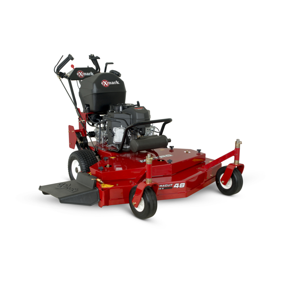
Exmark METRO Operator's Manual
Hide thumbs
Also See for METRO:
- Operator's manual (60 pages) ,
- Parts manual (20 pages) ,
- Setup instructions (7 pages)
Table of Contents
Advertisement
Quick Links
Advertisement
Table of Contents

Related Manuals for Exmark METRO


Summary of Contents for Exmark METRO
- Page 1 METRO ® For Serial Nos. 920,000 & Higher Part No. 4500-689 Rev. A...
- Page 2 Replacements may be ordered through the engine manufacturer. Exmark reserves the right to make changes or add improvements to its products at any time without incurring any obligation to make such changes to products manufactured previously.
-
Page 3: Introduction
All Exmark parts are thoroughly tested and inspected before leaving the factory, however, attention is required on your part if you are to obtain the fullest measure of satisfaction and performance. -
Page 4: Table Of Contents
Contents Belt Guide Adjustment ........30 Brake and Wheel Drive Linkage Adjustment ..........30 Introduction ............3 Shifter Lever Adjustment....... 32 Safety ..............5 Shifter Detent Adjustment......33 Safety Alert Symbol ......... 5 PTO Safety Switch Adjustment...... 33 Safe Operating Practices ........5 Handle Height Adjustment ...... -
Page 5: Safety
The owner is responsible for training the users. Institute in effect at the time of production. • Never let children or untrained people operate Exmark designed and tested this lawn mower to offer or service the equipment. Local regulations may reasonably safe service; however, failure to comply restrict the age of the operator. - Page 6 Safety DANGER DANGER In certain conditions gasoline is extremely In certain conditions during fueling, static flammable and vapors are explosive. electricity can be released causing a spark which can ignite gasoline vapors. A fire or A fire or explosion from gasoline can burn explosion from gasoline can burn you and you, others, and cause property damage.
- Page 7 Safety Operation damage and make repairs before restarting and operating the mower). WARNING – Before clearing blockages. Operating engine parts, especially the muffler, – Whenever you leave the mower. become extremely hot. Severe burns can occur • Stop engine, wait for all moving parts to stop, and on contact and debris, such as leaves, grass, engage parking brake: brush, etc.
-
Page 8: Maintenance And Storage
• Follow the manufacturer’s recommendations for safety of the machine. Failure to use original wheel weights or counter weights to improve Exmark parts could cause serious injury or stability. death. • Use extreme care with grass catchers or attachments. -
Page 9: Safety And Instructional Decals
Exmark equipment dealer or labels. distributor or from Exmark Mfg. Co. Inc. • Replace all worn, damaged, or missing safety • Safety signs may be affixed by peeling off the signs. - Page 10 Safety 1-403143 103-2076 98-5954 103-2244 ECS Units Only 103-1623 ECS Units Only 103-2245 ECS Units Only 103-1798...
- Page 11 Safety 117–2718 103-5626 48 inch Deck Units Only 103-1967 Pistol Grip Units Only...
-
Page 12: Specifications
• Engine Specifications: See your Engine Owner’s • Speed range: Manual – 1st: 2.0 mph (3.22 km/hr) • Engine Oil Type: Exmark 4–Cycle Premium – 2nd: 2.7 mph (4.35 km/hr) Engine Oil – 3rd: 3.5 mph (5.63 km/hr) • RPM: Full Speed: 3600 (No Load) –... -
Page 13: Dimensions
Specifications Cutting Deck Overall Length: • Cutting Width: 32 inch 36 inch 48 inch Deck Deck Deck – 32 inch Deck: 31.75 inches (80.7 cm) Standard 78.0 inches 78.0 inches 73.0 inches – 36 inch Deck: 35.38 inches (89.9 cm) Pistol Grip (198.1 cm) (198.1 cm) -
Page 14: Product Overview
Operation Product Overview Operation Note: Determine the left and right sides of the machine from the normal operating position. Controls Operator Presence Control (OPC) Levers Located on the upper handle assembly directly above the handle grips. When these levers are depressed, the OPC system senses that the operator is in the normal operator’s Figure 3 position. -
Page 15: Choke Control
Operation Choke Control Located on the front left corner of the fuel tank support. Choke is used to aid in starting a cold engine. The choke control is pulled out to be in the “ON” position and pushed in to be in the “OFF” position. Do Not run a warm engine with choke in the “ON”... -
Page 16: Pre-Start
Operation Pre-Start PTO Engagement Fill fuel tank on level ground. For best results use DANGER only clean, fresh regular grade unleaded gasoline with The rotating blades under the mower deck are an octane rating of 87 or higher. dangerous. Blade contact can cause serious Important: Never use methanol, gasoline injury or kill you. -
Page 17: Driving The Machine
Operation 7. Remove the key to prevent children or other unauthorized persons from starting engine. 8. Close the fuel shut-off valve when the machine will not be in use for a few days, when transporting, or when the unit is parked inside a building. -
Page 18: Transporting
Operation To place the drive levers in the “drive” position, Smoothly release both drive levers to engage drive slightly squeeze the drive levers while placing wheels. thumbs on the outer thumb lobe of the neutral Pull the unit backward to “assist” with the movement lock/park brake latches (or the index finger on of the unit. -
Page 19: Maintenance
Maintenance Maintenance Note: Determine the left and right sides of the machine from the normal operating position. WARNING WARNING While maintenance or adjustments are being The engine can become very hot. Touching a hot made, someone could start the engine. engine can cause severe burns. -
Page 20: Periodic Maintenance
4. If the oil level is low, wipe off the area around the oil fill cap, remove cap and fill to the “FULL” Figure 8 mark on the dipstick. Exmark 4-Cycle Premium Engine Oil is recommended; refer to the Engine 1. Spring disc washer (cone towards bolt head) Owner’s manual for an acceptable alternative. -
Page 21: Check Safety Interlock System
Engine Owner’s manual for additional information.) Service Interval: Before each use or daily Every 200 hours/Yearly 1. For your safety, your Exmark mower is equipped (whichever comes with Operator Presence Controls, referred to as first)—Replace the paper (OPC). When either the PTO is engaged, or the element. -
Page 22: Change Engine Oil
Clean around oil filter and unscrew filter to remove. Before the new filter is installed, Lubricate Grease Fittings apply a thin coating of Exmark 4–Cycle Premium Engine Oil on the surface of the rubber seal. Note: See chart for service intervals. -
Page 23: Check Spark Plugs
Maintenance Check Spark Plugs Lubrication Chart (cont'd.) Service Interval: Every 160 hours Fitting Initial Number of Places Service Locations Pumps Interval Remove spark plugs, check condition and reset gaps, 6. Trans- or replace with new plugs. See Engine Owner’s mission hours Manual. -
Page 24: Thread Locking Adhesives
Maintenance Copper-Based Anti-seize 6. Check for side play caused by bearing wear on the input and output shafts of the transmission. Copper-based anti-seize is used in the following Replace bearings if necessary. locations: 7. Remove the six bolts that fasten the upper case •... -
Page 25: Adjustments
Maintenance Adjustments than adjusting axle position and number of spacers below caster support hub). Note: Disengage PTO, shut off engine, wait for Note that: all moving parts to stop, engage parking brake, and remove key before servicing, cleaning, or making any •... -
Page 26: Adjusting The Axle Position
Maintenance Cutting Height Adjustment Table (1 inch to 4 1/4 inches (2.5 cm-10.8 cm)) (cont'd.) Cutting Axle Number Of Spacers Number of 1/4 inch (.64 cm) Blade Spacers Below Spindle Height Position Below Caster Range (Figure 10) Support Hub 3/16 inch inch (1.2 cm) -
Page 27: Adjusting The Number Of Spacers Below Caster Support Hub
Maintenance 8. With the jack, raise or lower the back end of the engine deck so that two axle adjustment bolts can be reinstalled in desired hole location. A tapered punch can be used to help align the holes. 9. Retighten all four bolts, lower unit and remove jack. -
Page 28: Transmission Belt Adjustment
Maintenance Wheel Drive Belt Pulley Height Adjustment Table and notes in the Adjusting the Cutting Height section. Scrapers 9. Install unused spacers between top of spindle and 1. Stop engine and wait for all moving parts to stop. spindle nut. Engage parking brake. -
Page 29: Blade Brake Adjustment
Maintenance Check belt tension after the first hour of operation Mower Deck Belt Routings: and at least twice during the first 24 hours of operation. Adjust as necessary. Figure 13 Figure 14 48 inch Deck Shown for Reference Only 32 inch and 36 inch Mower Deck 1. -
Page 30: Belt Guide Adjustment
Maintenance distance should be between 1/8 inch and 3/16 inch (3–5 mm) (see Figure 16). 5. Engage the blade control and check to make sure the blade brake pad clears the sheave. Figure 18 48 inch Belt Guide Location (Viewed from underneath the deck) 1. - Page 31 Maintenance A. For wheel drive linkage adjustment, a slight upward force placed on the drive remove the hairpin between the neutral levers to remove any "slack" in the linkage. lock latch and drive lever (Figure 19). C. Re-install hairpin into hole on the clevis pin between the neutral lock/park brake latch and drive lever (See Figure 19).
-
Page 32: Shifter Lever Adjustment
Maintenance Figure 24 1. Shifter Lever 3. Adjustment slot 2. Equal distance • To adjust the shifter lever: 1. Remove the 3/8 inch nyloc nut and spring Figure 22 disc washer from the stud on top of the Right Side of Unit Shown transmission (See Figure 25). -
Page 33: Shifter Detent Adjustment
Maintenance Shifter Detent Adjustment Transmission shifter detent can be adjusted by adjusting the setscrew on the back side of transmission located just behind the neutral start switch. Turn setscrew in (clockwise) to hold the transmission shifter more positively in each gear and to increase the force on the lever required to shift gears. -
Page 34: Cleaning
Maintenance Cleaning Clean Engine and Exhaust System Area Service Interval: Before each use or daily (May be required more often in dry or dirty conditions.) CAUTION Excessive debris around engine cooling air intake and exhaust system area can cause engine Figure 27 and exhaust system area to overheat which can 1. -
Page 35: Clean Debris From Machine
Maintenance Clean Debris From Machine Service Interval: Before each use or daily 1. Stop engine, wait for all moving parts to stop, and remove key. Engage parking brake. 2. Clean off any oil, debris, or grass build-up on the machine and cutting deck, especially under deck belt shields, around the fuel tank, around engine and exhaust area. -
Page 36: Troubleshooting
Troubleshooting Troubleshooting Important: It is essential that all operator safety mechanisms be connected and in proper operating condition prior to mower use. When a problem occurs, do not overlook the simple causes. For example: starting problems could be caused by an empty fuel tank. The following table lists some of the common causes of trouble. - Page 37 Troubleshooting Problem Possible Cause Corrective Action Mower pulls left or right (with levers fully 1. Idler arm pulleys and drive sheaves are 1. Remove mud and/or grass buildup. forward). dirty. 2. Wheel drive belt pulley scrapers 2. Correct adjustment. adjustment is not correct 3.
-
Page 38: Schematics
Schematics Schematics SWITCH SWITCH N.O. TRANSMISSION N.C. SWITCH N.O. TO SAFETY INTERLOCK MODULE ENGINE GROUND BLACK ENGINE KILL TERMINAL CONNECTORS ARE VIEWED FROM WIRE END N.C. = NORMALLY CLOSED N.O. = NORMALLY OPEN G006816... - Page 39 No Claim of breach of warranty shall be cause for cancellation or rescission of the contract of sale of any Exmark mower. All warranty work must be performed by an authorized Exmark Service Dealer using Exmark approved replacement All implied warranties of merchantability (that the parts.
- Page 40 Notes:...
-
Page 41: Service Record
Service Record Date: Description of Work Done: Service Done By:... - Page 43 Figure 28 This page may be copied for personal use. 1. The maximum slope you can safely operate the machine on is 20 degrees. Use the slope indicator to determine the degree of slope of hills before operating. Do Not operate this machine on a slope greater than 20 degrees. Fold along the appropriate line to match the recommended slope.
- Page 44 SEE EXMARK’S COMPLETE LINE OF ACCESSORIES AND OPTIONS MID-MOUNT RIDING ACCESSORIES AND OPTIONS CUSTOM RIDE SEAT SUSPENSION SYSTEM OPERATOR CONTROLLED DISCHARGE FULL SUSPENSION SEAT ROLL OVER PROTECTION SYSTEM (ROPS) DECK LIFT ASSIST KIT SUN SHADE HITCH KIT TRASH CONTAINER LIGHT KIT...