Table of Contents
Advertisement
Quick Links
Advertisement
Table of Contents

Related Manuals for TYAN GT20 (B5502


Summary of Contents for TYAN GT20 (B5502
- Page 1 TYAN GT20 B5502 Service Engineer’s Manual http://www.tyan.com...
- Page 2 Neither this manual, nor any material contained herein, may be reproduced without written consent of manufacturer. ® Copyright 2010 MiTAC International Corporation. All rights reserved. TYAN is a registered trademark of MiTAC International Corporation. Version 1.0...
- Page 3 There will be danger of explosion if battery is incorrectly replaced. Replace only with the same or equivalent type recommended by manufacturer. Dispose of used battery according to manufacturer instructions and in accordance with your local regulations. http://www.tyan.com...
- Page 4 About this Manual This manual provides you with instructions on installing your TYAN GT20-B5502. This Manual is intended for experienced users and integrators with hardware knowledge of personal computers. This manual consists of the following parts: Chapter1: Provides an introduction to the TYAN GT20-B5502 barebones,...
- Page 5 SAFETY INFORMATION Before installing and using TYAN GT20-B5502, take note of the following precautions: ·Read all instructions carefully. ·Do not place the unit on an unstable surface, cart, or stand. ·Do not block the slots and opening on the unit, which are provided for ventilation.
-
Page 6: Table Of Contents
Table of Contents Chapter 1: Overview ................. 9 About the TYAN GT20-B5502 ..........9 Features.................. 10 Product Models............... 13 Standard Parts List ..............14 1.4.1 Box Contents ..............14 1.4.2 Accessories ..............15 About the Product ..............16 1.5.1 System Front View............16 1.5.2... - Page 7 Replacing the M1232 HDD Backplane Board ......57 3.7.1 M1232 HDD Backplane Board Features ......59 3.7.2 M1232 Connector Pin Definitions ........61 Appendix I: Cable Connection Tables .......... 65 Appendix II: FRU Parts Table ............67 Appendix III: Technical Support............ 69 http://www.tyan.com...
- Page 8 NOTE http://www.tyan.com...
-
Page 9: Chapter 1: Overview
Chapter 1: Overview About the TYAN GT20-B5502 Congratulations on the purchase of the TYAN GT20-B5502, a highly optimized ® rack mount barebone system. The GT20-B5502 is designed to support (1) Intel Xeon 3400 Series processor and up to 32GB RDIMM or 16GB UDIMM DDR3-800/1066/1333 memory per node. -
Page 10: Features
Features TYAN GT20B5502 (B5502G20V4H-LE) 1U Rackmount Form Factor Chassis Model GT20 Dimension (D x W x 25.4" x 17.2" x 1.72" (645 x 436 x 43.6mm) System S5502GM2NR-LE Motherboard ATX, 12"x9.6" (305x243.8mm) Board Dimension Gross Weight 15.96Kg Buttons (1) PWR / (1) RST / (1) NMI / (1) ID... - Page 11 2 Channels / Support 2 UDIMMs or 3 RDIMMs Memory channel per channel 1.5V Memory voltage PCI-E (1) PCI-E Gen.2 x16 slot Expansion Slots Pre-install TYAN M2091, PCI-E x16 1U riser card (left) Riser Card Port Q'ty Intel 82574L Controller Connector type D-Sub 15-pin...
- Page 12 /Power on mode after power recovery / User-configurable H/W monitoring / Auto-configurable of hard disk types Operating OS supported list Please visit our Web site for the latest update. System Class A FCC (DoC) CE (DoC) Regulation C-Tick VCCI http://www.tyan.com...
-
Page 13: Product Models
Barebone (1) GT20-B5502 Barebone (1) Quick Ref. Guide / (1) MB User's manual + (1) Manual BB User's manual Installation CD (1) TYAN installation CD (1) LGA1156 CPU heatsink Heatsink / Cooler Package Contains Rail kit (1) CRAL-0032, sliding rail kit for KGT20... -
Page 14: Standard Parts List
The product should arrive packaged as illustrated below. 1.4.1 Box Contents Component Description 1U chassis,(4) hot-swap HDDbays ® TYAN S5502 system board (pre-installed) 400W single Power Supply (4) System FAN Fan Duct M1008: LED control board (pre-installed) -
Page 15: Accessories
If any items are missing or appear damaged, contact your retailer or browse to ® TYAN ’s website for service: http://www.tyan.com ® The web site also provides information of other TYAN products, as well as FAQs, compatibility lists, BIOS settings, etc. ® 1 x TYAN Motherboard... -
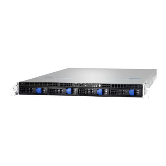
Page 16: About The Product
About the Product The following overview illustrations show you the features of the product. 1.5.1 System Front View 1.5.2 System Rear View http://www.tyan.com... -
Page 17: Led Definitions
Description Green 10Mb/100Mb/1000Mb linked RJ-45 Linkage/ Blinking Green 10Mb/100Mb/1000Mb activity Activity(left) No LAN linked Amber 1000Mb linked/activity RJ-45 Linkage/ Green 100Mb linked/activity Activity(Right) 10Mb mode or No LAN linked NOTE: “Left” and “Right” are viewed from the rear panel. http://www.tyan.com... - Page 18 ID LED State Color Description Blue System identified ID LED System not identified http://www.tyan.com...
-
Page 19: Motherboard (S5502) Layout
1.5.4 Motherboard (S5502) Layout The diagram is representative of the latest board revision available at the time of publishing. The board you receive may not look exactly like the above diagram. http://www.tyan.com... -
Page 20: Jumpers & Connectors
COM switch IPMB Connector Enable/Disable BMC jumper PSMI Connector Speaker Header Port80 Header SAS GPIO to Backplane PCH SGPIO 2X10_pin FAN connector LCM Header Jumper Legend OPEN - Jumper OFF Without jumper cover CLOSED - Jumper ON With jumper cover http://www.tyan.com... -
Page 21: System Block Diagram
1.5.6 System Block Diagram http://www.tyan.com... -
Page 22: Internal View
1.5.7 Internal View M2091 PCI-E Riser Card Assembly Power Supply System Fan Unit M1232 HDD Backplane Board HDD Cage http://www.tyan.com... -
Page 23: Chapter 2: Setting Up
A grounding strap or an anti-static pad Most of the electrical and mechanical connections can be disconnected with your hands. It is recommended that you do not use pliers to remove connectors as it may damage the soft metal or plastic parts of the connectors. http://www.tyan.com... -
Page 24: Precautions
Metallic parts or metal flakes can cause electrical shorts. NOTE: All connectors are keyed to only attach one way. All use the correct screw size as indicated in the procedures. http://www.tyan.com... -
Page 25: Installing Motherboard Components
CPUs, memory modules and add on cards. 2.1.1 Removing the Chassis Cover Follow these instructions to remove GT20-B5502 chassis cover. Unscrew the rear top cover on the back side as shown in the small diagram. Slide the rear top cover out. http://www.tyan.com... -
Page 26: Installing The Cpu And Heatsink
Follow the steps below on installing CPUs and CPU heatsink. Take off the air duct. Locate the CPU socket. Press the lever slightly away from the socket and then pull the CPU socket cover to a fully open position. http://www.tyan.com... - Page 27 Lift the CPU protection cap up and place the CPU into the socket. http://www.tyan.com...
- Page 28 Close the CPU socket cover and press the lever down to secure the CPU. http://www.tyan.com...
- Page 29 Position the heatsink on top of the CPU and secure it with 4 screws in an X pattern. Replace the air duct. http://www.tyan.com...
-
Page 30: Installing The Memory
Press the memory slot locking levers in the direction of the arrows as shown in the following illustration. Align the memory module with the slot. When inserted properly, the memory slot locking levers lock automatically onto the indentations at the ends of the module. http://www.tyan.com... - Page 31 http://www.tyan.com...
- Page 32 800, 1066 Rank (4x8GB) 256MB/52MB technology, x4 and x16 DRAM’s on RDIMM are not supported for Foxhollow chipsets Memory speed is dependent on type of CPU. Check CPU vendor specification for each CPU to understand max memory speed possible. http://www.tyan.com...
- Page 33 256MB technology, x4 DRAM on UDIMM and Quad Rank UDIMM are not supported X16 DRAM is not supported Memory speed is dependent on type of CPU. Check CPU vendor specification for each CPU to understand max memory speed possible. http://www.tyan.com...
-
Page 34: Installing Hard Drives
Installing Hard Drives The GT20-B5502 supports four (4) 3.5” hard drives. Follow these instructions to install a hard drive. Press the locking lever latch and pull the locking lever open. Slide the HDD tray out. Remove the 6 screws. http://www.tyan.com... - Page 35 Place a hard drive into the drive tray. Use 6 HDD screws to secure the HDD. Reinsert the HDD tray into the chassis and press the locking lever to secure the tray. http://www.tyan.com...
-
Page 36: Installing The Pci-E Cards
PCI-E card. Pull open the tab of PCI-E slot on the rear panel in the direction as shown to release the PCI-E bracket. Take out the PCI-E bracket. Insert the PCI-E card in the direction of arrow as shown. http://www.tyan.com... - Page 37 Close the tab of PCI-E slot to secure PCI-E card. http://www.tyan.com...
-
Page 38: Rack Mounting
Follow these instructions to mount the TYAN GT20-B5502 into an industry standard 19" rack. NOTE: Before mounting the TYAN GT20-B5502 in a rack, ensure that all internal components have been installed and that the unit has been fully tested. Screws List... -
Page 39: Installing The Inner Rails To The Chassis
2.2.2 Installing the inner Rails to the Chassis Screw the mounting ear to each side of TYAN GT20-B5502 as shown using (2) screws from the supplied screws kit. Draw out the inner rails from rail assembly. Install inner rails to left and right sides of chassis using 1 M4-4L(A) screw for each side. -
Page 40: Installing The Outer Rails To The Rack
Reserve the distance same as in Step 2 on rear bracket. Secure the rear bracket to outer rail with 2 M4-4L(A) screws. Secure the outer rail to the rack using 2 brackets and 4 M5-8L(B) screws for each side. Secure the mounting brackets from inside, not outside, of the rack. http://www.tyan.com... - Page 41 Mounting Bra cket http://www.tyan.com...
-
Page 42: Rack Mounting The Server
Lift the chassis and then insert the inner slide rails into the middle rails. Push the chassis in and press the latch key (A). Then push the whole system into the rack (B) Secure the mounting ears of chassis to the rack with 2 M5-15L(C) screws. http://www.tyan.com... - Page 43 NOTE: To avoid injury, it is strongly recommended that two people lift the TYAN GT20-B5502 into the place while a third person screws it to the rack. http://www.tyan.com...
- Page 44 NOTE http://www.tyan.com...
-
Page 45: Chapter 3: Replacing Pre-Installed Components
Motherboard, M1008 LED control board, M1232 HDD board, M2091 PCI-E Riser card, System fan, ODD drive, Power supply unit etc. Disassembly Flowchart The following flowchart outlines the disassembly procedure. Rear Components Chassis rear cover DIMMs Power CPU/Heatsink Assembly PCI Card M2091 PCI-E Riser card Mainboard Mainboard http://www.tyan.com... - Page 46 Front Components Chassis rear cover PCBs M1008 LED M1232 HDD Control Board Board http://www.tyan.com...
-
Page 47: Removing The Cover
The GT20-B7016 has one preinstalled PCI-E riser card, Follow the instructions below to disassemble the M2091 PCI-E riser card. Unscrew the riser card bracket and pull it up from the slot in the direction as shown. Unscrew the M2091 riser card. http://www.tyan.com... - Page 48 Install a new riser card onto the bracket following the procedures mentioned earlier in reverse order. http://www.tyan.com...
-
Page 49: Disconnecting All Motherboard Cables
Before replacing the motherboard or certain components, remove cables connected to the motherboard. Follow these instructions to remove all motherboard cables. Disconnect the power cables. Disconnect the USB and front panel cable. Disconnect the SGPIO, SATA and fan cables. http://www.tyan.com... -
Page 50: Removing The Motherboard
After removing all of the aforementioned cables, follow the instructions below to remove the motherboard from the chassis. Remove the heatsink and processor if installed. Remove the nine screws securing the motherboard to the chassis. Carefully lift the motherboard from the chassis. http://www.tyan.com... -
Page 51: Replacing The Led Control Board
Follow these instructions to replace the M1008 LED control board. Remove the two screws securing the LED control board unit to the chassis. Push the LED control board unit out and unplug the cables from the connectors at the back of the unit. http://www.tyan.com... - Page 52 Remove three screws securing the LED control board to the bracket. Lift the LED control board free from the chassis. After replacing the LED control board, insert the unit into the chassis following the above procedures in reverse. http://www.tyan.com...
-
Page 53: M1008 Led Control Board Features
M1008 LED Control Board Connector Pin Definition J1: USB Header Definition Definition USB1- USB2- USB1+ USB2+ J3: SSI Definition Definition PW_LED+ ID_LED+ PW_LED- ID_LED- HD/LAN3 LED+ SYS_FAULT1- HD/LAN3 LED- SYS_FAULT2- PWR_SW+ LAN1_LED+ PWR_SW- LAN1_LED- RESET+ ICH_SMBDAT RESET- ICH_SMBCLK ID_SW+ INTRU# TEMP_SENSER LAN2_LED+ EXT_INT LAN2_LED- http://www.tyan.com... -
Page 54: Replacing The System Fan
Replacing the System Fan Follow these instructions to replace the cooling fans in your system. Locate the cooling fans in your system. Unplug the cables connected to the mainboard and lift the fan unit up from the chassis. http://www.tyan.com... - Page 55 Follow Step A & B to unlock the fans. Step A Step B Follow Step C & D to take out the old fan and replace with a new one. Step C Step D http://www.tyan.com...
- Page 56 After replacing the new fans, follow Step A & B in reverse order to lock the fans. Reinstall the fans into the chassis. Connect the fan cables to the motherboard fan connectors. System Fan to S5502 MB System Fan Connect to S5502 MB → Fan1 → Fan2 → Fan3 → Fan4 http://www.tyan.com...
-
Page 57: Replacing The M1232 Hdd Backplane Board
Replacing the M1232 HDD Backplane Board Disconnect all cables connected to M1232 HDD Board. Power cable: SATA Power cable and Mini SAS cable: M1232 HDD Board to S5502 MB Cable M1232 Connect to S5502 MB → Mini-SAS Cable SATA0~3 http://www.tyan.com... - Page 58 Remove the three screws securing the bracket to the chassis base. Lift the bracket up from the chassis. Unscrew M1232 board from the bracket. Replace a new M1232 HDD Board and reinstall it into the chassis following the above steps in reverse. http://www.tyan.com...
-
Page 59: M1232 Hdd Backplane Board Features
3.7.1 M1232 HDD Backplane Board Features Front View J39: Mini SAS Connector http://www.tyan.com... - Page 60 Rear View LED1 LED2 LED4 LED3 LED6 LED5 LED7 LED8 http://www.tyan.com...
-
Page 61: M1232 Connector Pin Definitions
M1232 Connector Pin Definitions Definition +12V Definition Definition +12V +12V J15 SGPIO JTAG Definition Definition 3.3V J41 SGPIO for IOH Definition Definition SM_CLK SGPIO_0 SM_DATA SGPIO_1 SGPIO_2 SGPIO_3 HD_ERR_LED J5 Slim Hard Disk power Definition +12V J18 Slim CDROM power Definition +12V http://www.tyan.com... - Page 62 Pin 1-2 chose by CPU_PWM (Default) Pin 2-3 chose by CPU_PWM2 LED Definition: Color State Description HDD fail LED Amber SATA/SAS HDD fail (LED 2/4/6/8) No failure found SATA/SAS HDD ready Green Power/Access SATA/SAS HDD Blinking access activity (LED 1/3/5/7) Power disconnected http://www.tyan.com...
-
Page 63: Replacing The Power Supply
Replacing the Power Supply Disconnect the power cables from the motherboard and the HDD Backplane Board. PSU to S5502 MB Connect to S5502 MB → 2X12 PWR → PSU to M1232 Connect to M1232 → → http://www.tyan.com... - Page 64 Remove the screws that secure the power supply to the chassis. Take out the power unit and follow the above steps in reverse to install a new one. http://www.tyan.com...
-
Page 65: Appendix I: Cable Connection Tables
Connect to S5502 MB → Mini-SAS Cable SATA0~3 M1008 LED Control Board to S5502 MB Cable M1008 Connect to S5502 MB → Control Cable → USB Cable PSU to S5502 MB Connect to S5502 MB → 2X12 PWR → http://www.tyan.com... - Page 66 PSU to M1232 Connect to M1232 → → http://www.tyan.com...
-
Page 67: Appendix Ii: Fru Parts Table
GT20-B5502 FRU Parts Item Model Number Part Number Picture Quantity Description S5502GM2NR-LE Motherboard 411783000061 TYAN S5502GM2NR_LE_B Chassis Unit CCHA-0350 432782800001 Chassis Unit;GT20 B5502 Chassis Top Cover CCCV-0140 340772300001 GT20 Top Cover Front Bezel for GT20 Series 1U Chassis Front Bezel... - Page 68 422791500001 Mini SAS Cable, 200mm A/C Power Cord, CCBL-0310 332810000280 L=1830mm,US type A/C Power Cord, CCBL-0300 332810000281 L=1830mm,EU type Note: The table is subject to change without notice. Please visit our Web site at http://www.tyan.com for the latest update. http://www.tyan.com...
-
Page 69: Appendix Iii: Technical Support
Help Resources: 1. See the beep codes section of this manual. 2. See the TYAN’s website for FAQ’s, bulletins, driver updates, and other information: http://www.tyan.com 3. Contact your dealer for help before calling TYAN. 4. Check the TYAN user group: alt.comp.periphs.mainboard.TYAN... - Page 70 Return Merchandise Authorization (RMA) number. The RMA number should be prominently displayed on the outside of the shipping carton and the package should be mailed prepaid. TYAN will pay to have the board shipped back to you. ® TYAN GT20-B5502 Service Engineer’s Manual V1.00...