
Related Manuals for Vaillant VRC 400


Summary of Contents for Vaillant VRC 400
- Page 1 For the owner and the heating engineer Operating and Installation Manual VRC 400 Programmable weather compensator with separat HW time control...
-
Page 2: Table Of Contents
Control overview... . Vaillant warranty ... 23 Display overview... . - Page 3 12 Technical data....43 Installation ....28 Vaillant customer service ..43 9.1 Control installation ......28 9.2 Wall mounting .........
-
Page 4: Notes On The Documentation
Notes on the documentation Notes on the documentation Symbols used Please observe the safety instructions in The following information is intended to this manual for the installation of the help you throughout the entire docu- control. mentation. Further documents apply in combination with this installation and Danger operation manual. -
Page 5: Safety
Safety Safety The weather compensator must be installed by a qualified engineer, who is responsible for adhering to the existing standards and regulations. We accept no liability for any damage caused by failure to observe these instructions. Operating manual and installation manual for VRC 400 weather compensator... -
Page 6: Operating Manual
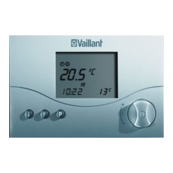
1 Control overview Operating manual Control overview Display 2 Dial (turn and click) Info button F Special functions button P Programming button/installer level Fig. 1.1 Control overview Operating Manual for VRC 400 weather compensator... -
Page 7: Display Overview
Display overview 2 Display overview Installer level and service/diagnosis level (see 11.1) 2 Info level (see 4.7) 3 Circulation pump symbol 4 Time/temperature display 5 Days of the week 6 Actual temperature 7 Operating modes (see 4.1) 8 Special functions (see 4.6) 9 Setting timer programmes (see 4.3) Fig. -
Page 8: Description Of The Control
The VRC 400 is a weather compensator with a weekly programme for heating, hot water and a circulation pump for connecting to Vaillant boilers with an eBus. The VRC 400 enables you to set heating programmes depending on the outside temperature. -
Page 9: Operation
Table 4.1 contains an overview of the The operating principle uses three but- operating modes you can select. tons and a dial (Vaillant “Turn and Click” The selected operating mode affects the operating concept). timer programmes both for heating and The display normally shows the current for hot water and the circulation pump. - Page 10 4 Operation Symbol Meaning Meaning Heating Hot water/circulation pump Automatic: According to the timer programmes set in the The hot water cylinder/circulation weather compensator, the heating circuit switches pump mode switches between heat- between heating mode and set-back mode ing ON and OFF according to the The heating circuit symbol is displayed if a heating timer programme set on the control- requirement is detected.
- Page 11 Operation 4 Symbol Meaning Meaning Heating Hot water/circulation pump ECO: According to the setted timer programmes, the See the table on the left heating circuit switches between heating mode and OFF. The heating circuit is switched off in set- back mode, provided the anti-frost function (activat- ed when the outside temperature is below 3 °C) is not active.
-
Page 12: Setting The Current Day And Time
4 Operation Setting the current day and time • Press the dial. The hours start flashing. • Turn the dial until you see the current To set the current day and time with the hour. display in normal mode, you must per- •... -
Page 13: Setting Timer Programmes
Operation 4 Setting timer programmes You can adapt the default programmes The controller is equipped with a basic to suit your needs. There are six steps to program (Table 4.2). setting the times you want: 1. Press the programming button P Time Day/Block of Start... - Page 14 4 Operation Display Required steps The table below illustrates the individual Press the programming steps again, using the example of the hot button P. The cursor (black water timer programme. triangle) marks the value If you want to change the timer pro- which can be changed ), which also flashes.
- Page 15 Operation 4 Display Required steps Display Required steps Press the dial. The cursor Press the dial. The cursor marks the days of week dis- marks the start time and the play, which also flashes. hour display flashes. Select a block of days or a Select the start time by single day of the week by turning the dial.
-
Page 16: Setting The Room Temperature
4 Operation If necessary, you can switch the weather You can set the room temperature compensator from the week programme directly from the basic display. If the to a daily programme. temperature level function is activated • With the display in normal mode, press on the installer level (setting different the F button for 10 seconds. - Page 17 Operation 4 move the set heating curve parallel on a 45° axis and the flow temperature calcu- lated by the weather compensator. Setting the required room temperature directly • Turn the dial (with the display in nor- mal mode). The current temperature display disap- pears, the sun symbol is displayed on the mode level and the required room temperature is shown (e.
- Page 18 4 Operation The display switches back to normal • Press the dial. T-H2 is displayed along mode after five seconds. with a set value. The set value flashes. Setting the room temperature for time • Turn the dial until you see the room windows temperature you want for the time win- (Only possible if the temperature level...
-
Page 19: Setting The Hot Water Temperature
Operation 4 The display switches back to normal Setting the hot water mode after five seconds. temperature You can set the hot water temperature Setting the set-back temperature from the basic display. “ECO” Please note the set maximum hot water •... -
Page 20: Activating Special Functions
4 Operation Display Required steps Activating special functions Energy-Saving function Press the F button to access the special The energy-saving function lets functions. You can activate the following you lower the heating for an adjustable period regardless of functions: the set heating programme. Press the special function button twice and the energy-saving symbol Display... - Page 21 Operation 4 Display Required steps Display Required steps Party function One-time recharging/ When you activate the party Cylinder Boost function the heating phase is con- This function allows you to fill tinued beyond the next set-back the cylinder, regardless of the phase.
-
Page 22: Info Level
4 Operation Display Required steps Info level Holiday function Press the info button to access the info The holiday function deactivates the weather compensator, but not level. The info symbol appears in the dis- the frost protection function. The play as soon as you open the info level. hot water and circulation pump are Each time you press the info button, dif- also deactivated. -
Page 23: Vaillant Warranty
Vaillant warranty - The set room temperature if the tem- perature level function is not activated (e.g.. TEMP 21.5 °C) We only grant a Vaillant manufacturer‘s - The current set-back temperature warranty if a suitably qualified engineer (e.g. ECO 15.0 °C) has installed the system in accordance - The set hot water temperature (e.g. -
Page 24: Recycling And Disposal
6 Recycling and disposal Recycling and disposal Neither the weather compensator or any of its accessories belong in the household waste. Make sure the old con- trol and any accessories are disposed of properly. Operating Manual for VRC 400 weather compensator... -
Page 25: Installation Manual
The CE label shows that the VRC 400 event of improper use or use for which it weather compensator, when connected is not intended. to Vaillant boilers, meets the basic requirements of the Council of Europe‘s The VRC 400 weather compensator is directive 89/336/EEC on electromagnet-... -
Page 26: Safety Instructions And Regulations
7 Information on installation and operation, 8 Safety instructions and regulations Safety instructions and hot water system or circulation pump regulations according to weather conditions, time and location, in connection with a Vail- lant boiler with an eBUS. The control must be installed by an Any other use or extended use is consid- approved company specialised in heating ered to be improper. -
Page 27: Safety Instructions
Safety instructions and regulations 8 Safety instructions Regulations All wiring must be in accordance with Danger! Building Regulations Part P, current IEE Risk of fatal electric shock from regulations, and all other relevant regu- touching live connections. lations and guidelines, and must be car- Before working on the control, ried out by a suitably qualified person. -
Page 28: Installation
8 Safety instructions and regulations, 9 Installation The controller may only be installed in screen and to push the controller into dry rooms. the supplied plug-in connection with a pin bar. Installation Wall mounting The VRC 400 weather compensator is The weather compensator can be alter- designed so that it can be used as a nately integrated in the boiler or e.g. - Page 29 Installation 9 air, unhindered by furniture, curtains or other objects. In the room where the controller is installed, all radiator valves must be fully open when using room modulation. The connection to the boiler is a 2-core bus cable (eBus), see fig. 10.1. •...
-
Page 30: Installing The Vrc 693 Outdoor Sensor
9 Installation • Connect the lead as described in sec- ing equipment and for the heating con- tion 10. troller. • Place the weather compensator (1) on the mounting box (5) so that the pins Installation location on the back of the upper section fit The outdoor sensor should be installed into the recesses (2). - Page 31 Installation 9 The location should not be protected from the wind, nor particularly exposed and it should not be exposed to direct sunlight. The device must be at least 1 m away from any opening in the outer wall, from which warm air can either continu- ously or occasionally issue.
- Page 32 9 Installation Caution! There is a risk of the wall and control becoming wet. Lay the cables properly and carefully to ensure that the out- door sensor and the building are not damaged by water. The control must be fixed to the wall in the correct position, as shown in fig.
-
Page 33: 10 Electrical Installation
Installation 9, Electrical installation 10 • Remove the cover (1) of the housing • Fix the top of the housing (1) to the and fix the housing to the wall using bottom (2) using the screws supplied. two screws through the fixing holes (8). -
Page 34: Connecting The Weather Compensator
10 Electrical installation 10.1 Connecting the weather com- Also follow the instructions for the boil- pensator er. Do not remove the jumper between ter- If the weather compensator is integrated minals 3 and 4 on the boiler. directly in the boiler, the electrical con- nection is directly through the pin bars 10.2 Connecting the outside sensor that are introduced in the connecting... -
Page 35: Start-Up
Electrical installation 10, Start-up 11 Start-up Certain system parameters have to be set in order for them to best suit the actual conditions. These system parame- ters are all together in the intaller level and should only be set by the heating engineer. -
Page 36: Installer Level
11 Start-up Display Setting by turning the dial 11.1 Installer level Press the P button to access the installer Set-back temperature level. Default setting: 15 °C • Press the P button for 10 seconds. Adjustment range: 5 ... 30 °C The spanner symbol and the first parameter appear in the display. - Page 37 Start-up 11 Display Setting by turning the dial Display Setting by turning the dial Anti-legionnaire’s disease Heating curve system The heating curve repre- 1=Activate the anti-legion- sents the ratio between out- naire‘s disease function. side temperature and target Every Wednesday, one flow temperature.
- Page 38 11 Start-up Display Setting by turning the dial Display Setting by turning the dial Minimum temperature Outside temperature shut- (foot point) down threshold Adjustment range Shurtdown temperature for 15 ... 90 °C demand-based deactivation Default setting: 15 °C of heating Adjustment range: Frost protection delay 5 ...
- Page 39 Start-up 11 Display Setting by turning the dial Display Setting by turning the dial Hydraulic switch Year setting 1 = Activation of sensor For activation of the recording when the hydrau- calendar lic switch is used, default setting 0 = Off Day setting Temperature level For activation of the...
-
Page 40: Service/Diagnostic Level
11 Start-up Display Setting by turning the dial 11.2 Service/diagnostic level Access the service/diagnostic level by Temperature level time pressing the P button and the dial. window H1 • Press the P button and the dial simul- (only when temperature taneously for 3 seconds. - Page 41 Start-up 11 Dial Test Test procedure Press and push Heating request A heating request of 50 °C is simulated. The burner on the P button for 3 boiler starts up and the pump starts (only up to the maxi- seconds mum flow temperature of the boiler).
-
Page 42: Handing Over To The Owner
11 Start-up Restore default settings 11.3 Handing over to the owner • To restore the controller to its default The owner of the weather controller condition, press the P button for 15 sec- must be instructed about its functions onds. and how to operate it. -
Page 43: 12 Technical Data
Technical data 12, Vaillant customer service 13 13 Vaillant customer 12 Technical data service Description Unit Operating voltage Umax To ensure regular servicing, it is strongly Maximum ambient tempera- °C recommended that arrangements are ture made for a Maintenance Agreement. - Page 44 EC declaration of conformity Operating manual and installation manual for VRC 400 weather compensator...