Table of Contents
Advertisement
O
M
PERATOR'S
ANUAL
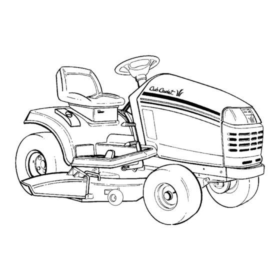
SERIES 2000
TRACTOR
Model Number
LT 2138
IMPORTANT: READ SAFETY RULES AND INSTRUCTIONS CAREFULLY
Warning:
This unit is equipped with an internal combustion engine and should not be used on or near any unimproved forest-
covered, brush-covered or grass-covered land unless the engine's exhaust system is equipped with a spark arrester meeting
applicable local or state laws (if any). If a spark arrester is used, it should be maintained in effective working order by the operator.
In the State of California the above is required by law (Section 4442 of the California Public Resources Code). Other states may have
similar laws. Federal laws apply on federal lands. A spark arrester for the muffler is available through your nearest engine authorized
service dealer or contact the service department, P.O. Box 361131 Cleveland, Ohio 44136-0019.
CUB CADET LLC P.O. BOX 361131 CLEVELAND, OHIO 44136-0019 [www.cubcadet.com]
PRINTED IN U.S.A.
FORM NO. 770-10282E
(11/03)
Advertisement
Table of Contents

Related Manuals for Cub Cadet LT 2138


Summary of Contents for Cub Cadet LT 2138
-
Page 1: Model Number
Federal laws apply on federal lands. A spark arrester for the muffler is available through your nearest engine authorized service dealer or contact the service department, P.O. Box 361131 Cleveland, Ohio 44136-0019. CUB CADET LLC P.O. BOX 361131 CLEVELAND, OHIO 44136-0019 [www.cubcadet.com] PRINTED IN U.S.A. - Page 2 KOHLER CO. FEDERAL AND CALIFORNIA EMISSION CONTROL SYSTEMS LIMITED WARRANTY SMALL OFF-ROAD EQUIPMENT ENGINES The U.S. Environmental Protection Agency (EPA), the California Air Resources Board (CARB), and Kohler Co. are pleased to explain the Federal and California Emission Control Systems Warranty on your small off-road equipment engine (herein engine). For California, engines produced in 1995 and later must be designed, built and equipped to meet the state’s stringent anti-smog standards.
- Page 3 CONTENTS Section Page Section Page Emission Control Systems Warranty ... Off-Season Storage ......Tractor and Deck Preparation....Mowing..........Safe Operation Practices ..... Optional Equipment and Accessories . Product Graphics ......... Maintenance Chart....... To The Owner ........Trouble Shooting........Calling Service Information ....Lubrication Table .........
-
Page 4: Important Safe Operation Practices
WARNING • The engine exhaust, some of its constituents, and certain vehicle components contain or emit chemicals known to the State of California to cause cancer, birth defects or other reproductive harm. • This unit is equipped with an internal combustion engine and should not be used on or near any unimproved forest-covered, brush-covered, or grass-covered land unless the engine’s exhaust system is equipped with a spark arrester meeting applicable local or state laws (if any). - Page 5 Do not use the grass catcher on steep slopes. exhaust presenting a potential fire hazard. 22. Use only accessories approved for this machine III. CHILDREN by Cub Cadet. Read, understand and follow all Tragic accidents can occur if the operator is not alert instructions provided...
- Page 6 5. Never allow children under 14 years old to 8. After striking a foreign object, stop the engine, operate the machine. Children 14 years and over remove the wire from the spark plug and should only operate the machine under close thoroughly inspect the mower for any damage.
-
Page 7: Product Graphics
PRODUCT GRAPHICS ing, painted over or can no longer be read. Replace- ment safety graphics are available through your Keep product safety graphics (decals) clean. Replace dealer. any safety graphic that is damaged, destroyed, miss- STARTING INSTRUCTIONS BE FAMILIAR WITH CONTROLS BEFORE STARTING ENGINE AND OPERATING. -
Page 8: To The Owner
LEVEL SURFACE before pulling the transmission release lever to the disengaged position. Your local authorized Cub Cadet dealer is interested in the performance you receive from your tractor, and with the maintenance needed to ensure the satisfactory operation of your tractor. The dealer has trained service personnel familiar with the latest servicing information, is equipped with the latest tools, and has a complete line of genuine Cub Cadet service parts which assure proper fit and high quality. - Page 9 SECTION I. CONTROLS AND INDICATORS Your Cub Cadet Tractor has been safety engineered. Thoroughly acquaint yourself with all the controls and This section gives a brief description of the function indicators before attempting to start or operate the and location of the various controls and indicators.
- Page 10 If the oil level is a uniform engine speed. within the operating range, but the light remains on, contact your Cub Cadet dealer. NOTE CAUTION When using power take-off operated equip- ment, best performance is achieved with the throttle lever in the “FAST”...
- Page 11 BRAKE PEDAL The brake pedal is located at the front of the right run- ning board above the forward control pedal. Press down to stop the tractor and disengage the cruise con- trol. The brake pedal must be fully depressed to acti- vate the safety interlock switch when starting the tractor.
- Page 12 8). Whenever engine maintenance is required, the tem should ever malfunction, do not operate the trac- side panels can be removed. tor. Contact your authorized Cub Cadet Dealer. The safety interlock system prevents the engine from cranking or starting unless the brake pedal is fully de- pressed, and the PTO switch is in the “OFF”...
- Page 13 UPPER FRONT WING NUT GRASP REAR WING NUT SIDE PANEL REAR TAB RETAINER WITH ON PANEL TAPERED GUIDE GRILLE GROOVE IN DASH PANEL GRASP Figure 8...
- Page 14 SECTION II. OPERATION Gasohol (up to 10% ethyl alcohol, 90% unleaded gasoline by volume) is an approved fuel. Other WARNING gasoline/alcohol blends are not approved. Methyl Tertiary Butyl Ether (MTBE) and unleaded RECEIVE INSTRUCTION Read gasoline blends (up to a maximum of 15% MTBE operator’s manual.
- Page 15 • The safety interlock system will automatical- TRACTOR BREAK-IN PROCEDURE ly shut off the engine if the operator leaves the seat before engaging the brake pedal lock. CAUTION • The safety interlock system will automatical- ly disengage the PTO if the reverse control Never operate a new engine immediately pedal is pressed down with the PTO in the under full load.
- Page 16 5. Turn the ingnition key to the “START” position and hold until the engine starts; however, do not crank CAUTION the engine continuously for more than 10 seconds at a time. Once the engine starts, gradually Do not use the forward or reverse control adjust the choke as needed to keep the engine pedals to change the direction of travel when running until warmed up, then push the choke control...
- Page 17 DRIVING ON SLOPES 1. Start and run the engine a few minutes to warm up. Refer to the SLOPE GAUGE on page 55 to help deter- 2. With the mowing deck, snow thrower, etc. installed mine slopes where you may not operate safely. and the engine running at approximately 50% throttle, engage and disengage the clutch at ten second intervals (ten seconds ON-ten seconds...
- Page 18 If brake rod 2. Release the brake pedal lock. If the tractor cannot adjustment does not correct the problem, see your be pushed forward or rearward, the braking force authorized Cub Cadet dealer. must be decreased.
- Page 19 WHEEL ALIGNMENT 5. Disconnect the front ball joints from the steering arms by removing the hex lock nuts (Refer to The front wheels should toe-in approximately 1/8 to Figure 13). Manually move each wheel to achieve 1/4 inch, as measured across dimensions A and B the required toe-in and equal D measurements.
- Page 20 2. Pivot the ends of the axle up and down to check for binding. If the axle is binding, loosen the lock nuts WARNING (See Figure 14) until binding is eliminated. Place the tractor on a firm and level surface and chock the front wheels before raising the rear PIVOT AXLE wheels from the ground.
- Page 21 1. Front Control Rod 2. Rear Control Rod 3. Hex Tap Screw CONTROL 4. Pivot Sleeve 5. Neutral Arm 6. Control Arm 7. Hex Cap Screw 8. Centering Spacer 9. Neutral Bracket 10. Hairpin Cotter (Not Shown) Figure 15. Adjusting the Control Rod ADJUSTING LIFT ASSIST SPRING TENSION The effort required to operate the implement lift handle After completing the previous steps (1 thru 4) for...
- Page 22 • Check fuel line for pinched or obstructed areas • Check for fuel filter blockage • Check for a clogged air filter Figure 17 If all of the above checks are okay and the engine continues to operate poorly, contact your Cub Cadet dealer.
- Page 23 OIL LEVEL are recommended. DIPSTICK Ambient Temperature Viscosity (Grade SG/SH) +32°F and Above — Cub Cadet Engine Oil S.A.E. 10W30 Below +32°F — Cub Cadet Engine Oil S.A.E. 5W20 or S.A.E. 5W30* *Synthetic Engine Oil S.A.E. 5W20 or S.A.E. 5W30 is acceptable.
- Page 24 To prevent loss of the cap, do not at every oil change interval. The filters can be remove the cap’s retaining ring from the drain obtained through your Cub Cadet dealer under part valve (Refer to Figure 19). Remove the dipstick. number KH-12-050-08.
- Page 25 FILLING THE CRANKCASE Check the oil level of the transmission case before each use to see that it is filled to the correct level. Before checking the transmission oil level, clean the CAUTION area around the oil fill plug/dipstick to prevent debris from entering the transmission case.
- Page 26 The filter can be “FULL” mark on the dipstick (Refer to Figure 20). obtained through your Cub Cadet dealer under the part number 923-3014. Refer to the LUBRICATION TABLE for information regarding the oil capacity and the proper type of oil to pour into the transmission case.
- Page 27 AIR CLEANER 3. Wash the precleaner in warm water with detergent. Rinse the precleaner thoroughly until all Check the air cleaner daily or before starting the traces of the detergent are eliminated. Squeeze engine. Check for loose or damaged components and out (do not wring) excess water in a dry cloth.
- Page 28 8. Install the new paper element and precleaner on the air cleaner base. NOTE 9. Install the cover plate on the carriage bolt and secure with the wing nut. Do not overtighten the Remove all dirt from around the spark plug wing nut, which could deform the cover plate.
- Page 29 HEADLIGHTS FUSES Refer to SPECIFICATIONS when replacement of Always use the same capacity fuse for replacement. head lamp bulbs is necessary. Refer to SPECIFICATIONS. If the electrical system does not function, check the fuses. WARNING To replace a fuse, pull the old fuse from the fuse holder and install the new fuse.
- Page 30 MAINTENANCE OF BATTERY BATTERY REMOVAL OR INSTALLATION The tractor is shipped with a wet battery — the battery acid has already been added and the battery sealed. WARNING Although the battery is maintenance free, the following care should be taken when handling the battery and to Battery posts, terminals...
- Page 31 3. Rotate the mounting rod fully upward toward the CHARGING THE BATTERY dash panel to provide clearance for battery Test and, if necessary, recharge the battery after the removal (Refer to Figure 27). tractor has been stored for a period of time. •...
- Page 32 MOUNTING TIRES ON THE RIM After mounting a new or old tire on the rim, inflate it to 20 pounds (maximum) pressure to seat the tire bead on the rim flange. Then deflate the tire to the corrrect WARNING operating pressure. Do not mount a tire unless you have the proper NOTE equipment.
- Page 33 SECTION V. MOWER DECK This section contains adjustment, removal, installation, SIDE-TO-SIDE LEVELING ADJUSTMENT and maintenance information for the 38-inch mower 1. Position the tractor and mower deck on a hard, deck. Instructions for installation and removal of the level surface. optional mulching plug are located at the end of this 2.
- Page 34 9. Loosen the upper jam nut on the hanger bracket and turn away from the adjustment ferrule. Turn the lower lock nut upward (tighten) on the threads of the hanger bracket to raise the right side of the mower deck. Turn the lock nut down (loosen) on the threads to lower the right side of the mower deck (Refer to Figure 30).
- Page 35 3. Initially adjust the front lift rod to allow 5/8 inch of thread to protrude beyond both lock nuts of the NOTE front lift rod/bracket assembly (Refer to Figure 32). The front lift rod must be against the back of FRONT LIFT both slots in the deck front roller bracket.
- Page 36 clearance between the wheel and level surface. Secure with the lock nut. NOTE e. Note the position of the index hole used; then Gauge wheels are intended to prevent scalping install the other rear gauge wheel and the front of the lawn, and are not meant to be used to set ball wheels into the corresponding index hole the cutting height.
-
Page 37: Deck Assembly
B. REMOVAL AND INSTALLATION OF MOWER DECK DECK ASSEMBLY CENTER DOUBLE PTO BELT PULLEY REMOVAL OF DECK WARNING Before removing the mower deck, place the PTO switch in the “OFF” position, engage the brake pedal lock, turn the ignition key to the “OFF”... - Page 38 7. Raise the tractor implement lift handle to its highest setting, Slide the mower deck forward, so WARNING the front lift rod rests to the rear of, and free of, the front roller bracket slots of the deck (See Figure The exhaust system is HOT.
- Page 39 INSTALLATION OF DECK TRACTOR LATCH RECEIVER WARNING (BOTH SIDES) Before performing the mower deck installation, place the PTO switch in the “OFF” position, engage the brake pedal lock, turn the ignition key to the “OFF” position and remove the key QUICK from the switch.
- Page 40 3. Make sure the slot in both rear deck brackets aligns with the implement lift links on each side of the tractor (See Figure 46). SLOT IN REAR DECK BRACKETS (BOTH SIDES) QUICK ATTACH ROD FRONT LIFT ROD/ BRACKET ASSEMBLY IMPLEMENT LIFT LINKS Figure 48...
- Page 41 NOTE REAR DECK BRACKET SLOTS It may be necessary to lift each side of the deck and maneuver it slightly to align the support pins with the holes of the lift links. Make certain the support pins are fully extended through the lift links to prevent the mower deck from disengaging the lift links while mowing.
- Page 42 PTO BELT CLUTCH PULLEY BELT MOWER DECK CENTER DOUBLE FRONT OF DECK PULLEY Figure 55 Figure 53 14. While holding the belt in position, rotate and 11. Pass the PTO belt downward, inside the tractor engage the deck idler arm lever into its stop frame, until the belt is below the two tractor front bracket to provide tension on the PTO belt (See lower pulleys.
- Page 43 After replacing the blades, apply grease to the exposed threads at the bottom of the spindle bolts to WARNING prevent rust buildup. When replacing the blades, be sure they are installed so When servicing the mower deck, be careful not that the wind wings are pointing upward toward the top of to cut yourself on the sharpened blades.
- Page 44 SPINDLE DRIVE BELT REPLACEMENT D. INSTALLATION OF MULCHING PLUG In order to replace the spindle drive belt, refer to Figure 58 and Figure 59 and proceed as follows: WARNING 1. Remove the hardware that secures the spindle Before installing the mulching plug, place the belt covers to the deck.
- Page 45 SECTION VI. OFF-SEASON STORAGE If the machine is to be inoperative for a period longer 2. If emptying the fuel system: than days, following procedures recommended: WARNING Do not drain fuel when the engine is hot. Allow WARNING the engine adequate time to cool. Drain fuel into an approved container outdoors, away from Never store the tractor with fuel in the tank open flame.
- Page 46 SECTION VII. MOWING MOWING WARNING To avoid possible injury, do not allow anyone in the area opposite the discharge chute while mowing. Although area been supposedly cleared of foreign objects, small objects may be picked up and discharged by the mower. WARNING Never direct the discharge of material toward bystanders or allow anyone near the machine...
-
Page 47: Optional Equipment And Accessories
Refer to the allied equipment can be purchased from, and installed attachment guide for a complete description of by, your authorized Cub Cadet dealer. equipment and required components that can be utilized with your tractor. -
Page 48: Maintenance Chart
MAINTENANCE CHART 10 hours 30 hours or 50 hours 100 hours Operation to Before or once three times or twice Before be performed each use a month a season a season yearly storage Clean grille, engine More often air inlet screen, dash under dirty intake screen and side conditions... -
Page 49: Trouble Shooting
TROUBLE SHOOTING Possible Cause Possible Remedy HARD TO START No gasoline in fuel tank or carburetor ..... Fill the tank with gasoline. Check the fuel line, carburetor and fuel filter. Fuel line or carburetor clogged........ Clean the fuel line and carburetor with a commercial carburetor cleaner. - Page 50 TROUBLE SHOOTING Possible Cause Possible Remedy LACK OF POWER Air cleaner clogged ..........Service the air cleaner element. Refer to “MAINTE- NANCE.” Engine overload ............Reduce the load. Engine overheated..........Make sure the air intake screen, shrouding, engine fins, side panels, dash intake screen and grille are free of accumulated dirt and debris.
-
Page 51: Lubrication Table
Cub Cadet Drive System Fluid Plus transmission case before needed 6 qts NOTE: Cub Cadet Drive System Fluid Plus is specially with filter each formulated for this application. If any other oil is used Cub Cadet will not be responsible for substandard performance. -
Page 52: Lubrication Guide
LUBRICATION GUIDE WARNING The service life and reliability of any machine depends upon the care it is given. Proper lubrication is a very important part of that care. This lubrication schedule reflects the minimal requirements to maintain the equipment. More frequent inspections and maintenance is preferable. NOTE: We do not recommend the use of a pressure Lubricant is cheap. - Page 53 LUBRICATION GUIDE —Before Each Use 1. Engine filler cap and Check the oil (with the engine stopped) and add sufficient new oil to bring it to dipstick the “FULL” mark on the dipstick. Do not overfill. Do not operate the engine if the oil level is below the “LOW”...
- Page 54 LUBRICATION GUIDE...
-
Page 55: Slope Gauge
SLOPE GAUGE (Keep this sheet in a safe place for future reference.) -
Page 57: Specifications
Engine Speed (governed) Low Speed ..............1200 RPM High Speed (no load) ........... 3600 RPM ± 75 Ignition ................Battery Spark Plug Gap (Cub Cadet No. 759-3336) .....030 in. ELECTRICAL SYSTEM System Voltage ............... 12 volt neg. ground Battery ................725-1706 Alternator ................. - Page 58 CUB CADET CORPORATION MANUFACTURER’S ONE YEAR LIMITED WARRANTY (COMMERCIAL USE) The limited warranty set forth below is given by CUB CADET CUB CADET does not extend any warranty for LLC (“CUB CADET”) with respect to new merchandise products sold or exported outside of the United...
- Page 59 CUB CADET will, at its option, repair or re- warranted product. place, free of charge, any PTO clutch or mounting hardware found to be defective in material or workmanship provided this product has been operated and maintained as set forth above.
-
Page 60: Maintenance Parts Chart
MAINTENANCE PARTS CHART MODEL LT 2138 SERIES 2000 16 HP KOHLER ENGINE OIL Engine Oil Requirements approx. . . 4 pints Part No. Cub Cadet engine oil Ambient temperature viscosity (Grade SG,SH,SJ or higher) Above +32°F SAE 10W30 737-3030A (10W30) Below +32°F...