Craftsman 247.889571 Operator's Manual
24" snow thrower
Hide thumbs
Also See for 247.889571:
- Operator's manual (76 pages) ,
- Operator's manual (12 pages) ,
- Operator's manual (76 pages)
Table of Contents
Advertisement
Available languages
Available languages
Operator's
Manual
CRRFTSMRN
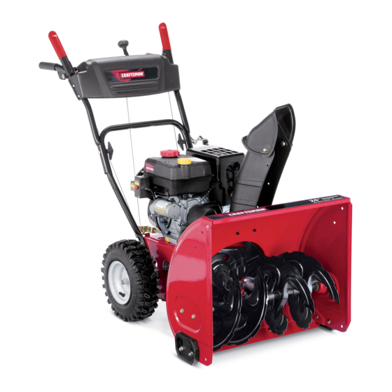
24" SNOW THROWER
Model No. 247.889571
CAUTION:
Before
using
this product,
read this
manual
and follow
all
safety
rules
and operating
instructions.
o SAFETY
ASSEMBLY
OPERATION
MAINTENANCE
PARTS LIST
o ESPANOL
Sears Brands
Management
Corporation,
Hoffman
Estates,
IL 60179, U.S.A.
Visit our website:
www.craftsman.com
FORMNO.769-05095C
5/16/2011
Advertisement
Table of Contents

Related Manuals for Craftsman 247.889571


Summary of Contents for Craftsman 247.889571
- Page 1 Model No. 247.889571 o SAFETY ASSEMBLY OPERATION MAINTENANCE PARTS LIST CAUTION: Before using o ESPANOL this product, read this manual and follow safety rules and operating instructions. Sears Brands Management Corporation, Hoffman Estates, IL 60179, U.S.A. Visit our website: www.craftsman.com FORMNO.769-05095C 5/16/2011...
-
Page 2: Specifications
This warranty isvoid ifthis product isever used w hile providing commercial services orifrented toanother person. w arrantycoverage details to obtain repairor replacement, v isit the website: www.craftsman.com This warranty covers ONLYdefects in material and workmanship. Warranty coverage does NOT include: •... - Page 3 This machinewas builtto be operatedaccordingto the safeopera- This symbolpointsout importantsafetyinstructionswhich,if not tion practicesin this manual.As with anytype of powerequipment, followed,couldendangerthepersonalsafetyand/orpropertyof carelessnessor error on the partof the operatorcan resultin serious yourselfand others. Readand followall instructionsin this manual injury.This machineis capableof amputatingfingers,hands,toes beforeattemptingto operatethis machine.Failureto complywith and feet and throwingdebris.Failureto observethe followingsafety these instructionsmay resultin personalinjury.Whenyou seethis...
- Page 4 Safe Handling of Gasoline • Exerciseextremecautionwhenoperatingon or crossinggravel surfaces.Stay alertfor hidden hazardsor traffic. Toavoidpersonalinjuryor propertydamageuseextremecare in handlinggasoline.Gasolineis extremelyflammableand the vaporsare • Exercisecautionwhenchangingdirectionand whileoperatingon explosive.Seriouspersonalinjurycan occurwhengasolineis spilled slopes.Do notoperateon steep slopes. on yourselfor yourclotheswhichcan ignite.Washyour skin and • Planyoursnow-throwing patternto avoiddischargetowards changeclothesimmediately.
- Page 5 MAINTENANCE & STORAGE DO NOT MODIFY ENGINE • Nevertamperwith safetydevices.Checktheirproperoperation Toavoidseriousinjuryor death,do not modifyengine in any way. regularly.Referto the maintenance and adjustmentsectionsof Tampering with the governorsettingcanlead to a runawayengineand this manual. cause it to operateat unsafespeeds.Nevertamperwithfactory setting of engine governor. •...
- Page 6 SAFETY SYMBOLS This pagedepictsand describessafetysymbolsthat mayappear on this product. Read,understand,and followall instructionson the machine beforeattemptingto assembleand operate. READ THE OPERATOR'S MANUAL(S) Read, understand, and follow all instructions in the manual(s) before attempting to assemble operate WARNING-- ROTATING BLADES Keep hands out of inlet and discharge openings while machine is running.
- Page 7 Thispage leftintentionally blank.
-
Page 8: Assembly
NOTE:References to rightor left sideof the snowthrowerare determined from behindthe unit in the operatingposition(standing directlybehindthe snow thrower,facingthe handlepanel). REMOVING FROM CARTON Cut the cornersof thecarton and lay the sidesflat on the ground. Removeand discard all packinginserts. Movethe snowthrowerout of thecarton. Makecertainthe carton has beencompletelyemptiedbefore discardingit. - Page 9 Positionthechute assemblyoverthe base.See Figure3. Closethe flangekeepersto securethechute assemblyto the chute base.See Figure4. The flangekeeperswill click intoplace whenproperlysecure. NOTE:If the flangekeeperswill noteasily clickinto place,usethe palmof yourhand to applyswift,firm pressureto the backof each. Removetheflat washerand hairpinclip from the end of the chutedirectionalcontrol. Insertthe end of the chutedirectionalcontrolinto the lower bracketand securewith the flat washerand hairpinclipjust removed.See Figure5.
- Page 10 SET-UP Chute Clean-Out Tool A chute clean-out tool is fastenedto the top of the augerhousing with a mountingclip. See Figure6. The tool is designedto cleara chuteassemblyof ice and snow.This item is fastenedwith a cabletie at the factory.Cut thecable tie beforeoperatingthe snowthrower. ChuteClean-outTool Neveruseyour handsto cleara cloggedchuteassembly.Shut off engineand remainbehind handlesuntilall movingpartshave...
- Page 11 Makecertain theentirebottomsurfaceof skid shoeis againstthe groundto avoidunevenwearon the skid shoes, ..Refightennutsand bolts securely, Chute Assembly Thedistancesnowis throwncan be adjustedby changingthe angle of the chuteassembly,Todo so: Stopthe engineby removingthe ignitionkeyand loosenthe plasticwingknobfoundon the left sideof the chuteassembly. Pivotthe chute upwardor downwardbeforeretightening thewing knob,See Figure8, Auger Control...
-
Page 12: Components View
Shift Lever Drive Control Auger Control Gas Cap Chute Assembly j.. ChuteDirectional Control Clean Out Mumer Recoil Starter Tool _._andle Primer Throttle Control Choke Control :[ectric Start Augers Button Oil Drain Skid Shoe Electric Starter Outlet Figure10 Nowthat youhaveset up yoursnowthrower,it'simportant to become acquainted with its controlsand features.Referto Figure10. - Page 13 THROTTLE CONTROL The augercontrol is locatedon the left handle.Squeezethe control grip againstthe handleto engagethe augerand startsnowthrowing action.Releaseto stop. DRIVE CONTROL/AUGER CONTROL LOCK aiW' DRIVE CONTROL Thethrottlecontrolis locatedon the rearof the engine.It regulatesthe speedof theengine and will shutoff the enginewhenmovedintothe OFF position. Depressingthe primerforcesfuel directlyinto ___144 the engine'scarburet°rt°...
-
Page 14: Clean-Out Tool
CLEAN-OUT TOOL • Refuelin a well-ventilated area with the enginestopped.Do not smokeor allowflamesor sparksin the areawherethe engineis refueledor wheregasolineisstored. Neveruse yourhandsto cleara cloggedchute assembly.Shut • Donot overfillthe fueltank.After refueling,makesurethe tank off engineand remainbehindhandlesuntilall movingpartshave cap is closed properlyand securely. stoppedbeforeusingthe clean-outtoolto clear thechute assembly. •... -
Page 15: To Engage Drive/Auger
TO ENGAGE DRIVE Movethrottlecontrolto FAST(rabbit)_T position. With the throttlecontrolin the Fast(rabbit) '_ position,move Movechoketo the CHOKE IJl position(coldenginestart). If shiftleverintoone of thesix forward(F) positionsor two reverse engineis warm,placechokein RUNposition. (R) positions.Selecta speedappropriatefor the snowconditions Pushprimerthree (3) times, makingsureto covervent hole in and a paceyou'recomfortable with. -
Page 16: Maintenance Schedule
MAINTENANCE SCHEDULE Before performing anytypeofmaintenance/service, disengage all Followthe maintenance schedulegiven below.This chart describes controls and stoptheengine. W aituntilall moving partshavecometo serviceguidelinesonly. Usethe ServiceLog columnto keeptrackof a completestop.Disconnect sparkplugwireandgrounditagainst t he completedmaintenance tasks.To locate the nearest Sears Service enginetoprevent u nintended starting. A lwayswearsafetyglasses during Centeror to scheduleservice,simplycontactSearsat 1-800-4-MY-HOME®. -
Page 17: Checking Spark Plug
Reinstallthe drain plugand tightenit securely. Refillwith the recommended oil and checkthe oil level.See Recommended Oil Usagechart.Theengine'soil capacityis 20 ounces. (%-400 -200 0o 200 400 Oil Drain ("c) -300 -200 -10° 0° Plug DONOTuse nondetergent o il or 2-strokeengineoil. It could shorten the engine'sservicelife. -
Page 18: Lubrication
become hot a nd can inc. LUBRICATION Gear Shaft Thegear (hex)shaft shouldbe lubricatedat least oncea seasonor afterevery 25 hoursof operation. Topreventspillage,removeall fuel fromtank by runningengine until it stops. Carefullypivotthe snowthrowerup and forwardso that it restson theauger housing. Removethe lowerframecover fromthe undersideof the snow throwerby removing the self-tappingscrewswhich secureit. - Page 19 ADJUSTMENTS Shift Cable If thefull rangeof speeds(forwardand reverse)cannotbe achieved, referto the figureto the rightand adjustthe shift cableas follows: Placethe shiftleverin thefastest forward speedposition(F6). Loosenthe hex nuton the shiftcable indexbracket.See Figure Pivotthe bracketdownwardto take up slack in the cable. Retightenthehex nut. Drive Control Whenthedrivecontrol is releasedand in thedisengaged"up"position, the cableshouldhavevery little slack.It shouldNOTbe tight.
- Page 20 Auger Control "_ Referto the Assemblysectionfor instructions on adjustingtheauger controlcable. Skid Shoes Referto the Assemblysectionfor instructions on adjustingthe skid shoes. BELT REPLACEMENT Auger Belt To removeand replaceyoursnow thrower'sauger belt, proceedas follows: Topreventspillage,removeall fuel fromtank by runningengine until itstops. Removethe plasticbelt coveron the front of the engineby remov- ing the two self-tappingscrews.See Figure22.
- Page 21 6. Remove the belt a sfollows. Refer toFigure 25. a. Loosen and remove the shoulder screw w hich a cts a sabelt keeper. b. Unhook the auger brake b racket spring from the frame. 7. Remove the belt f rom around the auger pulley, and slip the belt between thesupport bracket and the auger pulley.
- Page 22 4, Carefully pivot the snow thrower upand forward so that i trests o n the auger housing. 5. Remove the frame c over from the underside ofthe snow thrower byremoving the self-tapping screws which s ecure it.Refer to Figure 24, 6.
- Page 23 NOTE:Be carefulnot to damagethe threadson the shaft, Carefullypositionthe hexshaftdownwardand to the left before carefullyslidingthe frictionwheelassemblyoff the shaft. See Figure31. NOTE: If you'rereplacingthe frictionwheelassemblyas a whole, discardthe wornpartand slidethe newpart ontothe hexshaft. Followthe stepsabovein reverseorder to reassemble components. Performthetest previouslydescribedin the Drive Control section.
- Page 24 If the snowthrowerwillnot be usedfor30 daysor longer,or if it is the end of the snowseasonwhenthe last possibilityof snowis gone,the equipmentneedsto be storedproperly.Followstorageinstructionsbelowto ensuretop performance from the snowthrowerfor manymoreyears. PREPARING SNOW THROWER PREPARING ENGINE Whenstoringthe snowthrowerin an unventilatedor metal stor- Enginesstoredover30 days need to be drainedof fuel to prevent age shed,careshouldbe taken to rustprooftheequipment.Using deterioration and gumfrom formingin fuel systemor on essential a light oil or silicone,coat theequipment,especiallyanychains,...
-
Page 25: Troubleshooting
Enginefails to start Chokecontrolnot in CHOKEposition. Movechokecontrolto CHOKEposition. Sparkplugwire disconnected. Connectwireto sparkplug. Faultysparkplug. Clean,adjustgap,or replace. Fueltank emptyor stalefuel. Filltank with clean,freshgasoline. Enginenot primed. Primeengineas instructedin the OperationSection. Keynot inserted. Insertkeyfully intothe switch. Connectone end of the extensioncordto the electric Extensioncordnot connected(when usingelectricstartbutton,on modelsso starteroutletand the otherend to a three-prong equipped). - Page 26 Craftsman Snow Thrower IViodel 247.889571 ///'...
- Page 27 Craftsman Snow Thrower IViodel 247.889571 731-2635 SnowRemoval T oolMount 684-04107-0637 SpiralAssembly,LH 684-04057A-0637 ImpellerAssembly,12"Dia. 684-04108-0637 SpiralAssembly,RH 710-0347 HexScrew,3/8-16, 1.75,Gr5 731-04870 Spacer,1.25OD x .75 ID x 1.00 710-0451 Bolt,Carriage,5/16-18,.750Grl 736-0188 Washer,Flat, .76x 1.49x .06 710-04484 Screw, 5/16-18, 0 .750 741-0493A Bushing,Flange,.80 ID x .91OD 710-0703 Screw,Carriage,1/4-20,.750,Gr5...
- Page 28 Craftsman Snow Thrower Model 247.889571 y:,15,1 _4_,...
- Page 29 Craftsman Snow Thrower IViodel 247.889571 " 731-04869A Chute,FlangeKeeper 631-04133A HandleAssembly,ClutchLock,LH 946-04397A Cable,SpeedSelector 631-04134B HandleAssembly,ClutchLock,RH 749-04191A-0637 Handle,Upper,LH 684-04111B HandleAss'y,Engage,Red, LH 747-04263 EyeBolt, ChuteCrank 684-04112B HandleAss'y,Engage,Red, RH 790-00313-0637 Shift Lever J 631-04131B _ Chute,Lower(!nc!_Ref_# 27,Qty. 3) 731-04912B Chute,Lower,5.0 Dia. 732-04238 Spring,Torsion,.8156ID x .3038...
- Page 30 Craftsman Snow Thrower Model 247.889571...
- Page 31 Craftsman Snow Thrower IViodel 247.889571 656-04055 DiscAssembly,FrictionWheel 731-04873 Spacer,1.25x .75x 3.0 938-04168 Axle, .75x 22" 684-04153 FrictionWheelAssembly,5.50D 736-0329 Washer,Lock, 1/4 684-04154B-0637 SupportBracket,FrictionWheel 684-04156A Shift Assembly,Rod 710-0809 Hex Screw,1/4-20,1.25,Gr5 710-0191 Hex Screw,3/8-24, 1.25,Gr8 J 710-0627 J HexScrew,5/16-24,.750,Gr5 710-0788 Screw,1/4-20,1.000 710-0672 Hex Screw,5/16-24,1.25,Gr5 710-1652 Screw,1/4-20x .625...
- Page 32 Craftsman Snow Thrower Model 247.889571 777S32636 777X43688 ....DO HOT...."WnNVW S,UOZVU3dO QV3U"_ USEE85 ORFUEL "S33V:IUfIS 13AVId9 N O DNIZVU3dO COHTAiNJHG M ORE VULX3 3Sn"SH]QNVLS_B N3HM NOIiflVO IV:igUVHOSI{] THAH 10% ETHAHOL 1O]Ul{]H]A:IN 'S:IIURrNi SiO]rgO NMOUHi QIOAV Ol "_ "3NIHOVIAI 9NI31AUBS U 0 9NigO0313Nn ]UO:E]B Q 3dd01S 3AVHSlidVd9NIAOWllV-ilINn S31QNVH HDlnl9 BgVgN:_Si(] "_...
- Page 34 MTD CONSUMER GROUP INC (MTD), the California Air Resources Board (CARB) and the United States Environment Protection Agency (U. S. EPA) Emission Control System Warranty Statement (Owner's Defect Warranty Rights and Obligations) EMISSION CONTROLSYSTEM COVERAGE IS APPLICABLE TOCERTIFIEDENGINESPURCHASED IN CALIFORNIA IN 2005 ANDTHERE- AFTER,WHICHARE USEDIN CALIFORNIA, A NDTO CERTIFIED MODELYEAR2005 AND LATERENGINESWHICHARE PURCHASED AND USEDELSEWHERE IN THE UNITEDSTATES.
- Page 35 (4)Repair orreplacement ofany warranted part under the warranty provisions ofthis article m ust beperformed atnocharge tothe owner ata warranty station. (5)Notwithstanding the provisions ofSubsection (4) above, warranty services orrepairs must beprovided atallMTD distribution centers that are franchised toservice the subject engines. (6)The owner must not b echarged fordiagnostic labor that l eads tothe determination that a warranted...
- Page 36 Look For Relevant Emissions Durability Period and Air index information On Your Engine Emissions Label Engines that are certified to meet the California Air Resources Board (CARB) Tier 2 Emission Standards must display information regarding the Emissions Durability Period and the Air Index. Sears Brands Management Corporation makes this information available to the consumer on our emission...
- Page 37 Congratulations onmaking asmart purchase. Your new Craftsman@ Onceyou purchasethe Agreement,a simplephonecall is all that it product isdesigned and manufactured foryears ofdependable opera- takesfor youto scheduleservice.Youcan call anytimedayor night,or tion. But l ike allproducts, itmay require repair from time totime. That's schedulea serviceappointmentonline.
- Page 38 La presentegarantiase anula si se utilizaeste productoalguna vezpara prestarservicioscornerciales o si se Ioalquilaa otra persona. Paraobtener informaci6n sobre el alcance de la garantiay solieitar la reparaci6no el reemplazo, v isite el sitio Web: www.craftsman.com Esta garantia cubre0NICAMENTElos defectos en los rnateriales y en la rnano de obra. Esta garantia NOcubre: •...
- Page 39 Esta rn_.quina r ue construidapara seroperadade acuerdocon La presenciade este sirnboloindicaque setrata de instrucciones las reglasde seguridadcontenidasen este manual.AI igualque irnportantesde seguridadque se deben respetarpara evitar concualquiertipo de equipo rnotorizado, u n descuidoo error por poner en peligrosu seguridadpersonaly/o materialy la de otras partedel operadorpuedeproducirlesionesgraves.Esta rn_.quina personas.Lea y siga todaslas instruccionesde este manualantes es capazde arnputarrnanosy piesy de arrojarobjetoscon gran...
- Page 40 Manejo seguro de la gasolina • Nuncaoperela rn_.quina si falta un rnontajedel canalo si el rnisrnoest,. daSado.Mantengatodos losdispositivosde seguri- Paraevitar lesiones personales 0 daSosrnateriales tengarnucho dad en su lugaryen funcionarniento. cuidadocuandotrabajecon gasolina.La gasolinaes surnarnente inflarnabley sus vaporespuedencausarexplosiones. S i se derrarna •...
- Page 41 • Paraencenderel motor,jale de la cuerdalentarnente hasta que • SegOn la Cornisi6nde Seguridad de Productosparael Consu- sienta resistencia,luegojale r_.pidarnente. El replieguer_.pido de rnidorde los EstadosUnidos(CPSC)y la Agenciade Protecci6n la cuerdade arranque(tensi6nde retroceso)le jalar_,la rnanoy Arnbiental d e los EstadosUnidos(EPA),este productotieneuna el brazohaciael motor rn_.s r_.pido de Io que usted puedesoltar.
- Page 42 SiMBOLOS DE SEGURIDAD Esta p_ginadescribelossirnbolosy figurasde seguridadinternacionales que puedenapareceren este producto.Lea el manualdel operador )araobtenerla inforrnaci6n terrninadasobreseguridad,reunirse,operaci6ny rnantenimiento y reparaci6n. LEA ELMANUAL DELOPERADOR(S) Lea,entienda, y siga todas lasinstrucciones en el manual (es)antes de intentar reunirse y funcionar. LA ADVERTENCIA -- PLATOS ROTATORIOS Guarde manos de entrada y aperturas de la descarga mientras la m_iquina corre.
- Page 43 NOTA:las referencias al lado derechoo y ciertosde la m_.quina quitanievesedeterminandesdela parteposteriorde la unidaden posici6nde operaci6n(permaneciendo directamente detr_.sde la m_.quina quitanieve,mirandohaciael panelde la manija). EXTRACCI6N DE LA UNIDAD DE LA CAJA Corte lasesquinasde la cajade cart6ny exti_ndalaen el piso Quitey descartetodos los insertosde empaque. Saquela m_.quina quitanievede la caja.
- Page 44 SitOeel montajedel canalsobrela base.Vea la figura3. Cierrelos fijadoresde la bridapara asegurarel montajedel canal a la basedel canal. Veala figura4. Losfijadoresde la brida emitenun chasquidocuandoest_.nbien asegurados. NOTA:si los fijadoresde la brida no seajustanen su lugarf_.cilmente, utilice la palmade su rnanopara apfcar una presi6nr_.pida y firmeen la parteposteriorde cadauno.
- Page 45 CONFIGURACION "_ " Herramienta de Lirnpieza del Canal Hay una herrarnienta de lirnpiezadel canal iajustada a la parte superiorde la caja de la barrenacon un pasadorde ensarnNado.Vea la figura6. La herrarnienta est,. diseSadapara lirnpiarel hieloy la nievedel rnontajede un canal.Este productose sujeta rnedianteuna Herrarnienta de uni6nde cableen la f_.brica.
- Page 46 Paraajustarlas zapatasantideslizantes: Aflojelascuatrostuercashexagonales (dos en cada lado)y los pernosdel carro.Muevalas zapatasantideslizantes a la posici6n deseada.Vea la figura 7. Cornpruebe que toda la superficieinferiorde laszapatas antideslizantes est_ contrael sueloparaevitar un desgaste desparejode los rnisrnos. Vuelvaa ajustarbien las tuercasy los pernos. Ajuste del montaje del canal Es posibleajustar la distanciaa la cualse arroja la nievecarnbiandoel...
- Page 47 Hay dosvelocidadesde retroceso(R). La uno (1) es la rn_.s lenta,y la dos (2) es la rn_.s r_.pida. Cumple con los estandares de seguridad de ANSi Lasrn&quinas quitanievede Craftsman curnplen conlosest&ndares d e seguridad del instituto estadounidense d e est&ndares n acionales (ANSI).
- Page 48 CONTROL DEL REGULADOR El controlde la barrenaest,. ubicadoen la manijaizquierda.Apriete la empuSadura de controlcontra la manijapara engranarla barrenay empiecea quitarnieve.Suelteparaque se detenga. CONTROL DE LA TRANSMISION/CONTROL DE LA BARRENA DE CERRADURA El control del regulador estfi ubicado en la parte trasera del motor. Negula la velocidad del motor, y Io apaga cuando se Iocoloca en la S CONTROL DiE LA...
- Page 49 Paracarnbiarla direcci6nhaciala cual se arrojala nieve,gire el NOTA:No Io Ileneen exceso.El Ilenadoexcesivode aceite puede controldireccionaldel canal. hacerque el motorgenerehurno,que cuestearrancarloo fallas en la bujia. HERRAMIENTA DE LIIVIPIEZA Vuelvaa colocarel tap6n/la varillade aceitey ajuste confirrneza antes de arrancarel motor. Gasolina Nuncause sus rnanospara liberarun rnontajede canaltapado.Antes Utilicegasolinaparaautorn6viles(sinplornoo conbajo contenidode de destaparlo,apagueel motory perrnanezca detr_sde las rnanijas I plornopara rninirnizarlosdep6sitosen la c&rnarade cornbusti6n)con...
- Page 50 Arrancador el_ctrico Muevala palancadel cebadorhastala posici6nCHOKE I,'q¢l (encendidoconel motor en fifo). Si el motorya est,. caliente, ubiqueel cebadoren la posici6nOFE El arrancadorel_ctricoopcionalest&equipadocon un cable de ali- Presioneel cebadortres (3) veces,asegur_.ndose d e cubrirel rnentaci6n y un enchufede tres terrninales conectadosa tierray est,. orificio de ventilaci6ncuandoIo haga.Si el motorest,.
- Page 51 LISTA DE MANTENIMIENTO Antes de realizarcualquiertipo del rnantenirniento/servicio, suelte Siga la lista de rnantenirniento dada abajo.Estacarta describepautas todos los rnandosy pare el motor.Esperehasta quetodas las partes de servicios61o. U sela colurnnade Troncode Serviciopara guardar de rnovirniento hayanvenidoa una paradacornpleta.Desconecteel la pistade tareasde rnantenirniento cornpletadas. L ocalizarel rn_.s alarnbrede bujia y b_.selo contrael motorpara prevenirel cornienzo cercano Charnusca el Centrode Servicioo prograrnar el servicio,sirn- involuntario.
- Page 52 Cambio de aceite del motor NOTA:Carnbieel aceitedespu_sde las 5 prirnerashorasde operaci6ny despu_sde cada50 horasde operaci6no una vez por ternporada. Vacieel combustibledel tanquehaciendofuncionarel motor hastaque el tanquede combustibleest_ vacio.Cerci6resede que la tapadel combustibleest,. asegurada. Coloqueun recipiente adecuadopara recolectarel aceitebajo el tap6nde drenajede aceite. Retireel tap6nde drenajede aceite.Vea la Figura12.
- Page 53 Midala separaci6nde bujia con un calibrador.Corrijade ser necesariotorciendoel electrodolateral.Vea la Figura14.La separaci6n debe establecerseentre0,02y 0,03 pulgadas Electrodo (0,60-0,80ram). Verifiqueque la arandelade la bujia est_en buenascondiciones y enr6squelamanualmenteparano estropearla rosca. Unavez que la bujfaest_ colocada,apri_telacon una Ilavepara comprimirla arandela. NOTA:Cuandoinstaieuna bujia nueva,una vez colocadala bujia apriete1/2vuelta paracomprimirla arandela.Cuandovuelvaa co[ocar 0,02- 0,03 pulgadas una bujfausada,una vez colocadala bujia apriete1/8- 1/4de vuelta...
- Page 54 PLACA DE RASPADO Y ZAPATAS ANTIDESLIZANTES La placade raspadoy laszapatasantideslizantes ubicadasen la base de la rn_.quina quitanieveest_.n sujetasa desgaste.Peri6dicarnente deberiacontrolarlospernosy reernplazarlos c uandosea necesario. NOTA:Laszapatasde esta rn_.quina t ienendos bordesde desgaste. Cuandoun lado se desgasta,se las puede rotar 1800 para usarel otro horde.
- Page 55 Aflojela tuerca hexagonal i nferiordel soportedel cablede la transmisi6n,Veala figura 19, Ubiquela m6nsulahaciaarribapara brindarm_.s juego (o hacia abajo paraaumentarla tensi6ndel cable). Vuelvaa apretarla tuercahexagonalsuperior, Soporte del canal Si la espiralsituadaen la parteinferiordel controldireccionaldel canal no seenganchacompletamente conel montajedel canal,es posible ajustarel soportedel canal, Parahacerlo: Aflojelas dostuercasque sujetanel soportedel canaly cambie su posici6nligeramente.
- Page 56 Aflojey retireel tornillocon rebordeque actOacomoguarda de la correa.Vea la figura24. Desenganche el resortede la m_nsulade soportedel marco. Retirela correade alrededorde la poleade la barrenay deslice la mismaentre la m_nsulade soportey la polea de la barrena. Vea la figura25. Pararealizarel reensamblado de la correade la barrenasiga las instruccionesen orden inverso.
- Page 57 4. Gire c on cuidado larn_.quina quitanieve hacia a rriba y hacia delante dernanera que quede apoyada sobre l acaja dela barrena. 5. Saque lacubierta del m arco desde d ebajo delarn_.quina quita nieve r etirando los torniNos autorroscantes que la aseguran.
- Page 58 NOTA:Tengacuidadode no daSarlas roscasdel eje. Con cuidado,ubiqueel eje hexagonalhaciaabajoy haciala izquierdaantesde deslizarcon precauci6nel rnontajede la rueda de fricci6nfueradel eje.Vea la figura30. NOTA:Cuandosedesea reernplazar e l conjuntode la ruedade fricci6ncornpleto,descartela piezadesgastaday deslicela nueva piezaen el eje hexagonal. Parareensarnblar l os cornponentes siga lospasosanterioresen orden inverso.
- Page 59 Si no sevaa utiliza el equipo durante30 dfaso rn_.s, o sies el finalde la ternporada de nievey ya noexisteposibilidad deque nieve, e s necesario alrnacenar e l equipo de rnanera adecuada. S igalasinstrucciones d e alrnacenarniento quese indicana continuaci6n p aragarantizar e l rendirniento rn_.xirno d e la rn_.quina q uitanieve durante rnuchos a_os.
- Page 60 El motorno arranca La palancade obturaci6nno est,. en [a Pongael interruptor en la posici6nCHOKE(obtura- posici6nON (encendido) ci6n). Se ha desconectado el cablede la bujia Conecteel cablea la bujfa. La bujia nofunciona correctamente Limpie,ajustela distanciadisruptivao cambie. El tanquede combustibleest,. vado o el Lleneel tanquecongasolinalimpiay fresca.
- Page 61 Perdidade potencia El cable de la bujfaest,. flojo Conectey ajuste el cablede la bujfa. El orificio de ventilaci6ndel tap6nde Retireel hieloy la nievedel tap6nde Ilenadodel Ilenadodel combustibleest,. obstruido combustible.Cornpruebe que el orificiode venti- laci6nno est_ obstruido. El cable del controlde transrnisi6nnecesita La unidadno seautopropulsa Ajusteel cabledel controlde transrnisi6n.
- Page 62 MTD CONSUMER GROUP, iNC. (MTD), el Bordo de Recursos de Aire de California (CARB) y la Agencia de Protecci6n Medioambiental de Estados Unidos (U. S. EPA) Declaraci6n de Garantia del Sistema de Control de Emisiones (Derechos y obligaciones del propietario seg_n la garantia contra defectos) LA COBERTURADESISTEMADECONTROLDEEMISIONES APLICABLE A MOTORES CERTIFICADOS COMPRADOS ENCALIFORNIA EN2005 Y A PARTIRDE ENTONCES, QUESON USADOS EN CALIFORNIA, Y HASTA ANO2005 DE MODELOCERTIFICADO Y MOTORES POSTERIORES QUESON COMPRADOS Y USADOSENOTRAPARTEEN LOSESTADOS UNIDOS.
- Page 63 reernplazada segQn lagarantia segarantizar_, por e lresto d el p eriodo degarantia. (3) Cualquier pieza g arantizada que est_ prograrnada para reernplazo segQn elrnantenirniento requerido deconforrnidad con lasinstruc- clones escritas delaSubsecci6n (c)segarantiza por e lperiodo detiernpo anterior alaprirnera fecha d ereernplazo prograrnada para e sa pieza.
- Page 64 Busque el periodo de duraci6n de emisiones importantes yla informaci6n de clasificaci6n de aire en la etiqueta de emisiones de su motor Los motores cuyo cumpiimiento con los estAndares de emisi6n Tier 2 de la Comisi6n de Recursos Ambientales de California (CARB) est6 certificado deben exhibir la informaci6n relacionada con el periodo de duraci6n de ias emisiones y la clasificaci6n de aire.
- Page 65 Felicitaciones por haberrealizadouna adquisici6ninteligente.El Unavezadquiridoel Acuerdo,puedeprograrnar el serviciocon productoCraftsman@ que ha adquiridoest_ dise_adoy fabricado tan s61orealizaruna Ilarnadatelef6nica.PuedeIlarnaren cualquier para brindarrnuchosa_osde funcionarniento confiable.Perocorno mornento del dia o de la nocheo prograrnar un servicioen linea. todoslos productosa vecespuederequerirde reparaciones.Esen El Acuerdode Protecci6nde Reparaci6n es una cornprasin riesgo. esernornentocuandoel disponerde un Acuerdode protecci6npara Si ustedanula por alguna raz6nduranteel periodode garantiade reparaciones le puedeahorrardineroy problernas.
- Page 68 Your Home For troubleshooting, product manuals and expert advice: managernylife www.managemylife.com For repair - in your home - of all major brand appliances, lawn and garden equipment, or heating and cooling systems, no matter who made it, no matter who sold it! For the replacement parts, accessories owner's manuals that you need to do-it-yourself.