Craftsman Incredi-Pull 316.794450 Operator's Manual
Speed start incredi-pull 2-cycle electric start capable weedwacker gas trimmer
Hide thumbs
Also See for Incredi-Pull 316.794450:
- Operator's manual (24 pages) ,
- Operator's manual (24 pages)
Advertisement
Quick Links
Operator's
Manual
M
2-Cycle
Electric Start Capable
WEEDWACKER® GAS TRIMMER
Model No. 316.794450
U_F_VABLE
STArTinG
EA $ E _
CAUTION:
Before
using this product,
read this manual
and follow
all its Safety
Rules and Operating
instructions.
,, SAFETY
* ASSEMBLY
* OPERATION
* MAINTENANCE
* PARTS LIST
* ESPANOL, R 19
Sears Brands
Management
Corporation,
Hoffman
Estates,
IL 60179 U.S.A.
Visit our website:
www.craftsman.com
769-07749 P00
01/12
Advertisement

Related Manuals for Craftsman Incredi-Pull 316.794450


Summary of Contents for Craftsman Incredi-Pull 316.794450
- Page 1 * MAINTENANCE read this manual and follow all its Safety * PARTS LIST Rules and Operating instructions. * ESPANOL, R 19 Sears Brands Management Corporation, Hoffman Estates, IL 60179 U.S.A. Visit our website: www.craftsman.com 769-07749 P00 01/12...
- Page 2 TABLE OFCONTENTS Safety..........Warranty ..........Know Your U nit........Specifications ......... Assembly ..........OilandFuel ........... Starting a nd Stopping ........Operation ..........Maintenance ......... Cleaning andStorage ........Speed S tart Accessory ....... Troubleshooting ........Repair Protection Agreements ......
- Page 3 • iMPORTANT SAFETY iNSTRUCTiONS READ ALL iNSTRUCTiONS BEFORE OPERATING The trimmer attachment shield must always be in place while operating the unit. Do not operate unit without both trimming lines extended, and the proper line installed. Do not extend the WARNING: When using the unit, all safety rules must be trimming line beyond the length of the shield.
- Page 4 SAFETY & iNTERNATiONAL SYMBOLS This operator's manual describes safety and international symbols and pictographs that may appear on this product. Read the operator's manual for complete safety, assembly, operating and maintenance and repair information. SYMBOL MEANING SYMBOL MEANING = Indicates danger, warning or caution. May be used in o SAFETY ALERT SYMBOL conjunction with other symbols or pictographs.
- Page 5 This additional coverage does not apply to inner trimmer shaft components. For warranty coverage details to obtain free repair or replacement, visit the web site: www.craftsman.com This warranty covers ONLY defects in material and workmanship.
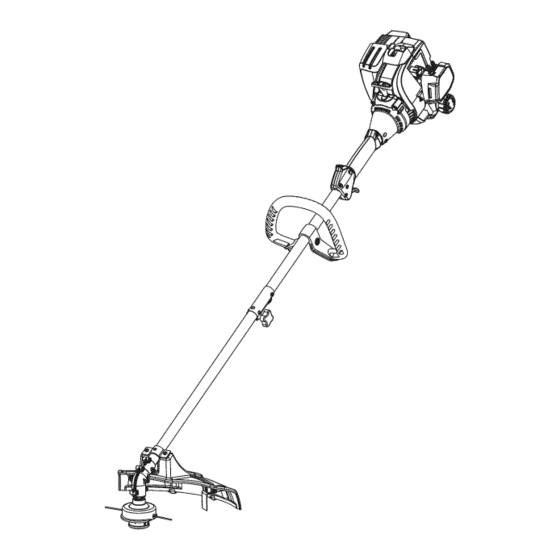
- Page 6 APPLiCATiONS Asatrimmer: Muffler Spark Plug • Cutting grass and light weeds. Starter Edging _,_Choke Lever • Decorative trimming around trees, fences, etc. Rope Grip_ __i-------- Other optional accessories may be used with this unit. Shaft Grip. _(;b-_ . ss oo. ,oo s o oo,o o oo,o _ \_ •...
- Page 7 iNSTALLiNG THE CUTTING HEAD SHIELD Screws (2} Cutting Head Shield operate the unit without the cutting head shield in place. WARNING: To prevent serious personal injury, never Use the following instructions if the cutting head shield is not installed. Use only the instructions that apply to the type of shaft and shield equipped with this unit.
- Page 8 OPERATING THE CONVERTIBLE COUPLER SYSTEM 90° Edging Hole (Trimmer Only) damage to the unit, shut the unit off before removing or [__J WARNING: To avoid serious personal injury and installing an attachment. NOTE: To make installing or removing the attachment easier, place the unit on the ground or on a work bench.
- Page 9 FUELING THE UNiT OiL AND FUEL MiXiNG iNSTRUCTiONS The use of old and/or improperly mixed fuel is the most common cause WARNING: Gasoline is extremely flammable. Ignited of performance problems. Use only fresh, clean unleaded gasoline. vapors may explode. Always stop the engine and allow it Follow the instructions carefully for the proper gasoline/oil mixture.
- Page 10 outdoor area. Carbon monoxide exhaust fumes can be I WARNING: lethal in a confined area. Operate this unit only in a well-ventilated serious injury, the operator and the unit must be in a stable [__J ARNING: Avoid accidentally starting the unit. To avoid position when pulling the starter rope (Fig.
- Page 11 i!lllIi!!!:!!ilii!!!i]i! i i ii!il!!!!i!Ii!i iiiii!t!iiii !!!! iii 11i!i!i!ii!l!iiilll NOTE: This unit can use a Speed Start Accessory! Please refer to the Speed Start accessory operator's manual for the proper use of this feature. (Items Sold Separately! Refer to the Speed Start Accessory section of this manual for more information about these Speed Start accessories.)
- Page 12 HOLDING THE TRIMMER he i 0, ha , oota body protection to reduce the risk of injury when operating this unit. • Stand in the operating position (Fig. 10). • Hold the shaft grip with the right hand. Keep the right arm slightly bent.
- Page 13 WARNING: To prevent serious injury, never perform maintenance or repairs while the unit is running. Always allow the unit to cool before servicing or repairing the unit. Disconnect the spark plug wire to prevent the unit from starting accidentally. MAINTENANCE SCHEDULE Perform these required maintenance procedures at the frequency Line...
- Page 14 Cleaning t heCutting Head Cutting Locking Tab Hole _ NOTE: The cutting head will r emain a ttached totheunit. Head 1. Remove theoldline from thecutting h ead. The line glide plate cannot beremoved ifthere isstill l ine inthecutting h ead. 2.
- Page 15 ADJUSTING THE iDLE SPEED [die Speed Screw adjustments. Wear protective clothing and observe all WARNIN6: The cutting head may spin during idle speed[ safety nstruct ons to prevent serous persona njury, NOTE: Careless adjustments can seriously damage the unit. A Sears or other qualified service dealer should make carburetor adjustments.
- Page 16 NOTE: Do not use fuel that has been stored for more than 30 days. Dispose of old fuel according to federal, state and local regulations. This unit can be started with an optional Speed Start accessory (items sold separately). Please contact your local Craftsman retailer, call 1-800-4-MY-HOME® or visit www.craftsman.com for more information.
- Page 17 PROBLEM SOLUTION The primer bulb was not pressed enough Press the primer bulb 10 times or until fuel is visible The fuel is old (over 30 days) and/or improperly mixed Drain the fuel tank and add fresh, properly mixed fuel The fuel is old (over 30 days) and/or improperly mixed Drain the fuel tank and add fresh, properly mixed fuel The fuel is old (over 30 days) and/or improperly mixed...
- Page 18 Congratulations on making a smart purchase. Your new Craftsman@ product is designed and manufactured for years of dependable operation. But like all products, it may require repair from time to time. That's when having a Repair Protection Agreement can save you money and aggravation.
- Page 19 OPERACION producto lea este manual y siga todas o MANTENIMIENTO las reglas de seguridad e instrucciones LISTA DE PIEZAS de operaci6n. Sears Brands Management Corporation, Hoffman Estates, IL 60179 U.S.A. Visite nuestro sitio web: www.craftsman.com 769-07749 P00 01/12...
- Page 20 TABLA DE CONTENIDO Seguridad ........... Garantia ..........Conozca su unidad ........Especificaciones ........Ensamblaje .......... Aceite y combustible ........Arranque y parada ........Operaci6n ........... Mantenimiento ........Limpieza y almacenamiento ......Accesorio Speed Start ........ Localizaci6n y soluci6n de problemas .....
- Page 21 • INSTRUCCIONES DE SEGURIDAD IMPORTANTES • LEA TODAS LAS INSTRUCCIONES ANTES DE OPERAR AL OPERAR LA UNIDAD LA UNIDAD Lleve puestas gafas o lentes de seguridad que cumplan las normas actuales ANSI y esten marcados como tales. Use siempre protecci6n para los oidos al operar esta unidad. Si la las normas de seguridad.
- Page 22 • Espere aqueelmotor s eenfrie para guardar otransportar la unidad. Cercierese deasegurar bien launidad a ltransportarla. Guarde l aunidad e nunlugar s eco, b ajo Ilave o enalto, a finde evitar suusenoautorizado oda_o. M antengala fuera del alcance delosni_os. Nomoje nirocie launidad c onagua niconningQn otroliquido. Mantenga losmangos secos, limpios y sinsuciedades.
- Page 23 Para conocer los detaHes de la cobertura de garantia para la reparaci6n o reemplazo gratuitos, visite el sitio web: www.craftsman.com Esta garantia cubre SOLAMENTE defectos de materiales o mano de obra. La cobertura de garantia NO incluye: •...
- Page 24 USOS Bujfa encendido Como recortadora: Silenciador Palanca del • Cortar cesped y malas hierbas escasas. Agarre de la obturador • Orillar (bordear) cuerda de arranque _/.-_4_ L_q;_ Con esta unidad se pueden utilizar otros accesorios opcionales. EmpuSadura del eje ,_-.//_t_. ,nterruptor de _(._ _Tapa...
- Page 25 INSTALAClON DEL PROTECTOR DEL CABEZAL DE CORTE TorniUos (2) Protector cabezal de corte graves, no opere nunca la unidad sin el protector del _ADVERTENClA: Para evitar lesiones personales cabezal de corte colocado. Soporte de montaje Si el protector del cabezal de corte no esta instalado, siga las instrucciones a continuaci6n.
- Page 26 OPERAR EL SISTEMA DE ACOPLADOR CONVERTIBLE Orificio de 90 ° para bordeadora (solo recortadora) y dados a la unidad, apague la unidad antes de quitar o DVERTENClA: Para evitar lesiones personales grave 1 instalar cualquier accesorio. NOTA: Para facilitar la instalaci6n o remoci6n de un accesorio, coloque la unidad sobre el suelo o sobre un banco de trabajo.
- Page 27 Mezclar el combustible INSTRUCCIONES PARA MEZCLAR EL ACEITE Y EL COMBUSTIBLE NOTA: Esta unidad trae un frasco de 3.2 onzas de aceite para motor de 2 tiempos. Para que la mezcla de combustible descrita El uso de un combustible viejo y/o mal mezclado es la causa mas anteriormente sea la correcta, echele la botella completa a un comQn de problemas de funcionamiento.
- Page 28 Apagado (O) / Parada a.rea exterior bien ventilada. El mon6xido de carbono de ADVERTENClA: Opere esta unidad solamente en un los gases de escape puede ser letal en un Area confinada. Encendido ( I ) /Arranque accidente. A fin de evitar lesiones graves, el operador y la unidad deben estar en una posici6n estable al tirar de la DVERTENOIA: Evite arrancar la unidad por...
- Page 29 NOTA: En esta unidad se puede usar un accesorio Speed Start Para utilizar correctamente este dispositivo, consulte el manual del operador del accesorio Speed Start (iLos accesorios se venden por separado! Para informarse mas sobre los accesorios Speed Start vaya a la secci6n Accesorio Speed Start este manual.) INSTRUCCIONES DE ARRANQUE...
- Page 30 SOSTENER L A RECORTADORA i ! ov o °c,,; ,o e a e taun,dad puesta protecci6n para los ojos, oidos, pies y cuerpo a fin de reducir el riesgo de lesiones. • Parese en la posici6n de operaci6n (Fig. 10). Sostenga la empu_adura del eje con la mano derecha.
- Page 31 ADVERTENClA: Para evitar lesiones graves, no haga nunca ningQn mantenimiento ni reparaci6n con la unidad funcionando. Siempre deje que la unidad se enfrie antes de darle mantenimiento o repararla. Desconecte el cable de la bujia para evitar que la unidad arranque por accidente. PLAN DE MANTENIMIENTO Lleve a cabo los procedimientos necesarios de mantenimiento...
- Page 32 Limpieza d el Cabezal de Corte Cabezal Orificio de la leng_Jeta_ NOTA: El cabezal de corte permanecera fijo a la unidad. de corte de traba _'_/_ 1. Quite la linea vieja del cabezal de corte. La placa deslizante de la linea no se puede quitar si todavia hay linea en el cabezal de corte.
- Page 33 AJUSTAR LA VELOCIDAD DE MARCHA EN VACiO Tornillo de rnarcha en vacfo ADVERTENClA: El cabezal de corte puede girar durante los ajustes de marcha en vacio. Use ropa de protecci6n y observe todas las instrucciones de seguridad para evitar lesiones personales graves. NOTA: Los ajustes negligentes pueden dafiar seriamente la unidad.
- Page 34 Esta unidad se puede arrancar con un accesorio opcional Speed Start (los accesorios se venden por separado). Para mas informaci6n, comuniquese con su distribuidor local Craftsman Ilamando al 1-800-4-MY-HOME® o visite www.craftsman.com. NQmero del articulo Descripci6n 316.85951 ....Arrancador de potencia electrico 316.85952 ....Arrancador...
- Page 35 PROBLEMA SOLUCION La pera del cebador no se oprimi6 Io suficiente Oprima la pera del cebador 10 veces o hasta que se vea el combustible El combustible esta viejo (tiene mas de 30 dias) y/o mal mezclado Vacie el tanque de combustible y eche combustible nuevo bien mezclado El combustible esta viejo (tiene mas de 30 dias) y/o mal mezclado Vacie el tanque de combustible y eche combustible nuevo bien mezclado...
- Page 36 Felicitaciones por haber hecho una compra inteligente. Su nuevo producto Craftsman@ fue dise_ado y fabricado con vistas a una operaci6n confiable por a_os. Pero como todos los productos, es posible que sea necesario repararlo alguna vez. Ahi es cuando tener un Convenio de Protecci6n de Reparacidn puede ahorrarle dinero y problemas.
- Page 38 REPLACEMENT PARTS - MODEL 316.794450 ELECTRIC START CAPABLE 2-CYCLE GAS TRIMMER Item Part No. Description Item Part No. Description Crankcase Bolt 753-06177 Rear Cover Assembly (includes 2 & 34) 791-182723 791-181345 Cover Screw 753-06275 Crankcase O-Ring 791-181862 Housing Screw 753-06189 Insulator Assembly (includes 22 &...
- Page 39 REPLACEMENT PARTS - MODEL 316.794450 ELECTRIC START CAPABLE 2-CYCLE GAS TRIMMER Item Part No. Description 753-06790 Throttle Housing Assembly (includes 2-4) 791-182405 Switch 753-04119 Throttle Trigger 791-182690 Throttle Trigger Spring 753-04344 Upper Shaft Housing Assembly 753-06039 D-Handle (includes 7) 753-06040 D-Handle Hardware 753-1190 Split Boom Coupler (includes 9-12)
- Page 40 Your Home For troubleshooting, product manuals and expert advice: managemylife www.managernylife.com For repair - in your home - of all major brand appliances, lawn and garden equipment, or heating and cooling systems, no matter who made it, no matter who sold it! For the replacement parts, accessories owner's...
- Page 41 * MAINTENANCE read this manual and follow all its Safety * PARTS LIST Rules and Operating instructions. * ESPANOL, R 19 Sears Brands Management Corporation, Hoffman Estates, IL 60179 U.S.A. Visit our website: www.craftsman.com 769-07749 P00 01/12...
- Page 42 TABLE OFCONTENTS Safety..........Warranty ..........Know Your U nit........Specifications ......... Assembly ..........OilandFuel ........... Starting a nd Stopping ........Operation ..........Maintenance ......... Cleaning andStorage ........Speed S tart Accessory ....... Troubleshooting ........Repair Protection Agreements ......
- Page 43 • iMPORTANT SAFETY iNSTRUCTiONS READ ALL iNSTRUCTiONS BEFORE OPERATING The trimmer attachment shield must always be in place while operating the unit. Do not operate unit without both trimming lines extended, and the proper line installed. Do not extend the WARNING: When using the unit, all safety rules must be trimming line beyond the length of the shield.
- Page 44 SAFETY & iNTERNATiONAL SYMBOLS This operator's manual describes safety and international symbols and pictographs that may appear on this product. Read the operator's manual for complete safety, assembly, operating and maintenance and repair information. SYMBOL MEANING SYMBOL MEANING = Indicates danger, warning or caution. May be used in o SAFETY ALERT SYMBOL conjunction with other symbols or pictographs.
- Page 45 This additional coverage does not apply to inner trimmer shaft components. For warranty coverage details to obtain free repair or replacement, visit the web site: www.craftsman.com This warranty covers ONLY defects in material and workmanship.
- Page 46 APPLiCATiONS Asatrimmer: Muffler Spark Plug • Cutting grass and light weeds. Starter Edging _,_Choke Lever • Decorative trimming around trees, fences, etc. Rope Grip_ __i-------- Other optional accessories may be used with this unit. Shaft Grip. _(;b-_ . ss oo. ,oo s o oo,o o oo,o _ \_ •...
- Page 47 iNSTALLiNG THE CUTTING HEAD SHIELD Screws (2} Cutting Head Shield operate the unit without the cutting head shield in place. WARNING: To prevent serious personal injury, never Use the following instructions if the cutting head shield is not installed. Use only the instructions that apply to the type of shaft and shield equipped with this unit.
- Page 48 OPERATING THE CONVERTIBLE COUPLER SYSTEM 90° Edging Hole (Trimmer Only) damage to the unit, shut the unit off before removing or [__J WARNING: To avoid serious personal injury and installing an attachment. NOTE: To make installing or removing the attachment easier, place the unit on the ground or on a work bench.
- Page 49 FUELING THE UNiT OiL AND FUEL MiXiNG iNSTRUCTiONS The use of old and/or improperly mixed fuel is the most common cause WARNING: Gasoline is extremely flammable. Ignited of performance problems. Use only fresh, clean unleaded gasoline. vapors may explode. Always stop the engine and allow it Follow the instructions carefully for the proper gasoline/oil mixture.
- Page 50 outdoor area. Carbon monoxide exhaust fumes can be I WARNING: lethal in a confined area. Operate this unit only in a well-ventilated serious injury, the operator and the unit must be in a stable [__J ARNING: Avoid accidentally starting the unit. To avoid position when pulling the starter rope (Fig.
- Page 51 i!lllIi!!!:!!ilii!!!i]i! i i ii!il!!!!i!Ii!i iiiii!t!iiii !!!! iii 11i!i!i!ii!l!iiilll NOTE: This unit can use a Speed Start Accessory! Please refer to the Speed Start accessory operator's manual for the proper use of this feature. (Items Sold Separately! Refer to the Speed Start Accessory section of this manual for more information about these Speed Start accessories.)
- Page 52 HOLDING THE TRIMMER he i 0, ha , oota body protection to reduce the risk of injury when operating this unit. • Stand in the operating position (Fig. 10). • Hold the shaft grip with the right hand. Keep the right arm slightly bent.
- Page 53 WARNING: To prevent serious injury, never perform maintenance or repairs while the unit is running. Always allow the unit to cool before servicing or repairing the unit. Disconnect the spark plug wire to prevent the unit from starting accidentally. MAINTENANCE SCHEDULE Perform these required maintenance procedures at the frequency Line...
- Page 54 Cleaning t heCutting Head Cutting Locking Tab Hole _ NOTE: The cutting head will r emain a ttached totheunit. Head 1. Remove theoldline from thecutting h ead. The line glide plate cannot beremoved ifthere isstill l ine inthecutting h ead. 2.
- Page 55 ADJUSTING THE iDLE SPEED [die Speed Screw adjustments. Wear protective clothing and observe all WARNIN6: The cutting head may spin during idle speed[ safety nstruct ons to prevent serous persona njury, NOTE: Careless adjustments can seriously damage the unit. A Sears or other qualified service dealer should make carburetor adjustments.
- Page 56 NOTE: Do not use fuel that has been stored for more than 30 days. Dispose of old fuel according to federal, state and local regulations. This unit can be started with an optional Speed Start accessory (items sold separately). Please contact your local Craftsman retailer, call 1-800-4-MY-HOME® or visit www.craftsman.com for more information.
- Page 57 PROBLEM SOLUTION The primer bulb was not pressed enough Press the primer bulb 10 times or until fuel is visible The fuel is old (over 30 days) and/or improperly mixed Drain the fuel tank and add fresh, properly mixed fuel The fuel is old (over 30 days) and/or improperly mixed Drain the fuel tank and add fresh, properly mixed fuel The fuel is old (over 30 days) and/or improperly mixed...
- Page 58 Congratulations on making a smart purchase. Your new Craftsman@ product is designed and manufactured for years of dependable operation. But like all products, it may require repair from time to time. That's when having a Repair Protection Agreement can save you money and aggravation.
- Page 59 OPERACION producto lea este manual y siga todas o MANTENIMIENTO las reglas de seguridad e instrucciones LISTA DE PIEZAS de operaci6n. Sears Brands Management Corporation, Hoffman Estates, IL 60179 U.S.A. Visite nuestro sitio web: www.craftsman.com 769-07749 P00 01/12...
- Page 60 TABLA DE CONTENIDO Seguridad ........... Garantia ..........Conozca su unidad ........Especificaciones ........Ensamblaje .......... Aceite y combustible ........Arranque y parada ........Operaci6n ........... Mantenimiento ........Limpieza y almacenamiento ......Accesorio Speed Start ........ Localizaci6n y soluci6n de problemas .....
- Page 61 • INSTRUCCIONES DE SEGURIDAD IMPORTANTES • LEA TODAS LAS INSTRUCCIONES ANTES DE OPERAR AL OPERAR LA UNIDAD LA UNIDAD Lleve puestas gafas o lentes de seguridad que cumplan las normas actuales ANSI y esten marcados como tales. Use siempre protecci6n para los oidos al operar esta unidad. Si la las normas de seguridad.
- Page 62 • Espere aqueelmotor s eenfrie para guardar otransportar la unidad. Cercierese deasegurar bien launidad a ltransportarla. Guarde l aunidad e nunlugar s eco, b ajo Ilave o enalto, a finde evitar suusenoautorizado oda_o. M antengala fuera del alcance delosni_os. Nomoje nirocie launidad c onagua niconningQn otroliquido. Mantenga losmangos secos, limpios y sinsuciedades.
- Page 63 Para conocer los detaHes de la cobertura de garantia para la reparaci6n o reemplazo gratuitos, visite el sitio web: www.craftsman.com Esta garantia cubre SOLAMENTE defectos de materiales o mano de obra. La cobertura de garantia NO incluye: •...
- Page 64 USOS Bujfa encendido Como recortadora: Silenciador Palanca del • Cortar cesped y malas hierbas escasas. Agarre de la obturador • Orillar (bordear) cuerda de arranque _/.-_4_ L_q;_ Con esta unidad se pueden utilizar otros accesorios opcionales. EmpuSadura del eje ,_-.//_t_. ,nterruptor de _(._ _Tapa...
- Page 65 INSTALAClON DEL PROTECTOR DEL CABEZAL DE CORTE TorniUos (2) Protector cabezal de corte graves, no opere nunca la unidad sin el protector del _ADVERTENClA: Para evitar lesiones personales cabezal de corte colocado. Soporte de montaje Si el protector del cabezal de corte no esta instalado, siga las instrucciones a continuaci6n.
- Page 66 OPERAR EL SISTEMA DE ACOPLADOR CONVERTIBLE Orificio de 90 ° para bordeadora (solo recortadora) y dados a la unidad, apague la unidad antes de quitar o DVERTENClA: Para evitar lesiones personales grave 1 instalar cualquier accesorio. NOTA: Para facilitar la instalaci6n o remoci6n de un accesorio, coloque la unidad sobre el suelo o sobre un banco de trabajo.
- Page 67 Mezclar el combustible INSTRUCCIONES PARA MEZCLAR EL ACEITE Y EL COMBUSTIBLE NOTA: Esta unidad trae un frasco de 3.2 onzas de aceite para motor de 2 tiempos. Para que la mezcla de combustible descrita El uso de un combustible viejo y/o mal mezclado es la causa mas anteriormente sea la correcta, echele la botella completa a un comQn de problemas de funcionamiento.
- Page 68 Apagado (O) / Parada a.rea exterior bien ventilada. El mon6xido de carbono de ADVERTENClA: Opere esta unidad solamente en un los gases de escape puede ser letal en un Area confinada. Encendido ( I ) /Arranque accidente. A fin de evitar lesiones graves, el operador y la unidad deben estar en una posici6n estable al tirar de la DVERTENOIA: Evite arrancar la unidad por...
- Page 69 NOTA: En esta unidad se puede usar un accesorio Speed Start Para utilizar correctamente este dispositivo, consulte el manual del operador del accesorio Speed Start (iLos accesorios se venden por separado! Para informarse mas sobre los accesorios Speed Start vaya a la secci6n Accesorio Speed Start este manual.) INSTRUCCIONES DE ARRANQUE...
- Page 70 SOSTENER L A RECORTADORA i ! ov o °c,,; ,o e a e taun,dad puesta protecci6n para los ojos, oidos, pies y cuerpo a fin de reducir el riesgo de lesiones. • Parese en la posici6n de operaci6n (Fig. 10). Sostenga la empu_adura del eje con la mano derecha.
- Page 71 ADVERTENClA: Para evitar lesiones graves, no haga nunca ningQn mantenimiento ni reparaci6n con la unidad funcionando. Siempre deje que la unidad se enfrie antes de darle mantenimiento o repararla. Desconecte el cable de la bujia para evitar que la unidad arranque por accidente. PLAN DE MANTENIMIENTO Lleve a cabo los procedimientos necesarios de mantenimiento...
- Page 72 Limpieza d el Cabezal de Corte Cabezal Orificio de la leng_Jeta_ NOTA: El cabezal de corte permanecera fijo a la unidad. de corte de traba _'_/_ 1. Quite la linea vieja del cabezal de corte. La placa deslizante de la linea no se puede quitar si todavia hay linea en el cabezal de corte.
- Page 73 AJUSTAR LA VELOCIDAD DE MARCHA EN VACiO Tornillo de rnarcha en vacfo ADVERTENClA: El cabezal de corte puede girar durante los ajustes de marcha en vacio. Use ropa de protecci6n y observe todas las instrucciones de seguridad para evitar lesiones personales graves. NOTA: Los ajustes negligentes pueden dafiar seriamente la unidad.
- Page 74 Esta unidad se puede arrancar con un accesorio opcional Speed Start (los accesorios se venden por separado). Para mas informaci6n, comuniquese con su distribuidor local Craftsman Ilamando al 1-800-4-MY-HOME® o visite www.craftsman.com. NQmero del articulo Descripci6n 316.85951 ....Arrancador de potencia electrico 316.85952 ....Arrancador...
- Page 75 PROBLEMA SOLUCION La pera del cebador no se oprimi6 Io suficiente Oprima la pera del cebador 10 veces o hasta que se vea el combustible El combustible esta viejo (tiene mas de 30 dias) y/o mal mezclado Vacie el tanque de combustible y eche combustible nuevo bien mezclado El combustible esta viejo (tiene mas de 30 dias) y/o mal mezclado Vacie el tanque de combustible y eche combustible nuevo bien mezclado...
- Page 76 Felicitaciones por haber hecho una compra inteligente. Su nuevo producto Craftsman@ fue dise_ado y fabricado con vistas a una operaci6n confiable por a_os. Pero como todos los productos, es posible que sea necesario repararlo alguna vez. Ahi es cuando tener un Convenio de Protecci6n de Reparacidn puede ahorrarle dinero y problemas.
- Page 78 REPLACEMENT PARTS - MODEL 316.794450 ELECTRIC START CAPABLE 2-CYCLE GAS TRIMMER Item Part No. Description Item Part No. Description Crankcase Bolt 753-06177 Rear Cover Assembly (includes 2 & 34) 791-182723 791-181345 Cover Screw 753-06275 Crankcase O-Ring 791-181862 Housing Screw 753-06189 Insulator Assembly (includes 22 &...
- Page 79 REPLACEMENT PARTS - MODEL 316.794450 ELECTRIC START CAPABLE 2-CYCLE GAS TRIMMER Item Part No. Description 753-06790 Throttle Housing Assembly (includes 2-4) 791-182405 Switch 753-04119 Throttle Trigger 791-182690 Throttle Trigger Spring 753-04344 Upper Shaft Housing Assembly 753-06039 D-Handle (includes 7) 753-06040 D-Handle Hardware 753-1190 Split Boom Coupler (includes 9-12)
- Page 80 Your Home For troubleshooting, product manuals and expert advice: managemylife www.managernylife.com For repair - in your home - of all major brand appliances, lawn and garden equipment, or heating and cooling systems, no matter who made it, no matter who sold it! For the replacement parts, accessories owner's...
- Page 81 * MAINTENANCE read this manual and follow all its Safety * PARTS LIST Rules and Operating instructions. * ESPANOL, R 19 Sears Brands Management Corporation, Hoffman Estates, IL 60179 U.S.A. Visit our website: www.craftsman.com 769-07749 P00 01/12...
- Page 82 TABLE OFCONTENTS Safety..........Warranty ..........Know Your U nit........Specifications ......... Assembly ..........OilandFuel ........... Starting a nd Stopping ........Operation ..........Maintenance ......... Cleaning andStorage ........Speed S tart Accessory ....... Troubleshooting ........Repair Protection Agreements ......
- Page 83 • iMPORTANT SAFETY iNSTRUCTiONS READ ALL iNSTRUCTiONS BEFORE OPERATING The trimmer attachment shield must always be in place while operating the unit. Do not operate unit without both trimming lines extended, and the proper line installed. Do not extend the WARNING: When using the unit, all safety rules must be trimming line beyond the length of the shield.
- Page 84 SAFETY & iNTERNATiONAL SYMBOLS This operator's manual describes safety and international symbols and pictographs that may appear on this product. Read the operator's manual for complete safety, assembly, operating and maintenance and repair information. SYMBOL MEANING SYMBOL MEANING = Indicates danger, warning or caution. May be used in o SAFETY ALERT SYMBOL conjunction with other symbols or pictographs.
- Page 85 This additional coverage does not apply to inner trimmer shaft components. For warranty coverage details to obtain free repair or replacement, visit the web site: www.craftsman.com This warranty covers ONLY defects in material and workmanship.
- Page 86 APPLiCATiONS Asatrimmer: Muffler Spark Plug • Cutting grass and light weeds. Starter Edging _,_Choke Lever • Decorative trimming around trees, fences, etc. Rope Grip_ __i-------- Other optional accessories may be used with this unit. Shaft Grip. _(;b-_ . ss oo. ,oo s o oo,o o oo,o _ \_ •...
- Page 87 iNSTALLiNG THE CUTTING HEAD SHIELD Screws (2} Cutting Head Shield operate the unit without the cutting head shield in place. WARNING: To prevent serious personal injury, never Use the following instructions if the cutting head shield is not installed. Use only the instructions that apply to the type of shaft and shield equipped with this unit.
- Page 88 OPERATING THE CONVERTIBLE COUPLER SYSTEM 90° Edging Hole (Trimmer Only) damage to the unit, shut the unit off before removing or [__J WARNING: To avoid serious personal injury and installing an attachment. NOTE: To make installing or removing the attachment easier, place the unit on the ground or on a work bench.
- Page 89 FUELING THE UNiT OiL AND FUEL MiXiNG iNSTRUCTiONS The use of old and/or improperly mixed fuel is the most common cause WARNING: Gasoline is extremely flammable. Ignited of performance problems. Use only fresh, clean unleaded gasoline. vapors may explode. Always stop the engine and allow it Follow the instructions carefully for the proper gasoline/oil mixture.
- Page 90 outdoor area. Carbon monoxide exhaust fumes can be I WARNING: lethal in a confined area. Operate this unit only in a well-ventilated serious injury, the operator and the unit must be in a stable [__J ARNING: Avoid accidentally starting the unit. To avoid position when pulling the starter rope (Fig.
- Page 91 i!lllIi!!!:!!ilii!!!i]i! i i ii!il!!!!i!Ii!i iiiii!t!iiii !!!! iii 11i!i!i!ii!l!iiilll NOTE: This unit can use a Speed Start Accessory! Please refer to the Speed Start accessory operator's manual for the proper use of this feature. (Items Sold Separately! Refer to the Speed Start Accessory section of this manual for more information about these Speed Start accessories.)
- Page 92 HOLDING THE TRIMMER he i 0, ha , oota body protection to reduce the risk of injury when operating this unit. • Stand in the operating position (Fig. 10). • Hold the shaft grip with the right hand. Keep the right arm slightly bent.
- Page 93 WARNING: To prevent serious injury, never perform maintenance or repairs while the unit is running. Always allow the unit to cool before servicing or repairing the unit. Disconnect the spark plug wire to prevent the unit from starting accidentally. MAINTENANCE SCHEDULE Perform these required maintenance procedures at the frequency Line...
- Page 94 Cleaning t heCutting Head Cutting Locking Tab Hole _ NOTE: The cutting head will r emain a ttached totheunit. Head 1. Remove theoldline from thecutting h ead. The line glide plate cannot beremoved ifthere isstill l ine inthecutting h ead. 2.
- Page 95 ADJUSTING THE iDLE SPEED [die Speed Screw adjustments. Wear protective clothing and observe all WARNIN6: The cutting head may spin during idle speed[ safety nstruct ons to prevent serous persona njury, NOTE: Careless adjustments can seriously damage the unit. A Sears or other qualified service dealer should make carburetor adjustments.
- Page 96 NOTE: Do not use fuel that has been stored for more than 30 days. Dispose of old fuel according to federal, state and local regulations. This unit can be started with an optional Speed Start accessory (items sold separately). Please contact your local Craftsman retailer, call 1-800-4-MY-HOME® or visit www.craftsman.com for more information.
- Page 97 PROBLEM SOLUTION The primer bulb was not pressed enough Press the primer bulb 10 times or until fuel is visible The fuel is old (over 30 days) and/or improperly mixed Drain the fuel tank and add fresh, properly mixed fuel The fuel is old (over 30 days) and/or improperly mixed Drain the fuel tank and add fresh, properly mixed fuel The fuel is old (over 30 days) and/or improperly mixed...
- Page 98 Congratulations on making a smart purchase. Your new Craftsman@ product is designed and manufactured for years of dependable operation. But like all products, it may require repair from time to time. That's when having a Repair Protection Agreement can save you money and aggravation.
- Page 99 OPERACION producto lea este manual y siga todas o MANTENIMIENTO las reglas de seguridad e instrucciones LISTA DE PIEZAS de operaci6n. Sears Brands Management Corporation, Hoffman Estates, IL 60179 U.S.A. Visite nuestro sitio web: www.craftsman.com 769-07749 P00 01/12...
- Page 100 TABLA DE CONTENIDO Seguridad ........... Garantia ..........Conozca su unidad ........Especificaciones ........Ensamblaje .......... Aceite y combustible ........Arranque y parada ........Operaci6n ........... Mantenimiento ........Limpieza y almacenamiento ......Accesorio Speed Start ........ Localizaci6n y soluci6n de problemas .....
- Page 101 • INSTRUCCIONES DE SEGURIDAD IMPORTANTES • LEA TODAS LAS INSTRUCCIONES ANTES DE OPERAR AL OPERAR LA UNIDAD LA UNIDAD Lleve puestas gafas o lentes de seguridad que cumplan las normas actuales ANSI y esten marcados como tales. Use siempre protecci6n para los oidos al operar esta unidad. Si la las normas de seguridad.
- Page 102 • Espere aqueelmotor s eenfrie para guardar otransportar la unidad. Cercierese deasegurar bien launidad a ltransportarla. Guarde l aunidad e nunlugar s eco, b ajo Ilave o enalto, a finde evitar suusenoautorizado oda_o. M antengala fuera del alcance delosni_os. Nomoje nirocie launidad c onagua niconningQn otroliquido. Mantenga losmangos secos, limpios y sinsuciedades.
- Page 103 Para conocer los detaHes de la cobertura de garantia para la reparaci6n o reemplazo gratuitos, visite el sitio web: www.craftsman.com Esta garantia cubre SOLAMENTE defectos de materiales o mano de obra. La cobertura de garantia NO incluye: •...
- Page 104 USOS Bujfa encendido Como recortadora: Silenciador Palanca del • Cortar cesped y malas hierbas escasas. Agarre de la obturador • Orillar (bordear) cuerda de arranque _/.-_4_ L_q;_ Con esta unidad se pueden utilizar otros accesorios opcionales. EmpuSadura del eje ,_-.//_t_. ,nterruptor de _(._ _Tapa...
- Page 105 INSTALAClON DEL PROTECTOR DEL CABEZAL DE CORTE TorniUos (2) Protector cabezal de corte graves, no opere nunca la unidad sin el protector del _ADVERTENClA: Para evitar lesiones personales cabezal de corte colocado. Soporte de montaje Si el protector del cabezal de corte no esta instalado, siga las instrucciones a continuaci6n.
- Page 106 OPERAR EL SISTEMA DE ACOPLADOR CONVERTIBLE Orificio de 90 ° para bordeadora (solo recortadora) y dados a la unidad, apague la unidad antes de quitar o DVERTENClA: Para evitar lesiones personales grave 1 instalar cualquier accesorio. NOTA: Para facilitar la instalaci6n o remoci6n de un accesorio, coloque la unidad sobre el suelo o sobre un banco de trabajo.
- Page 107 Mezclar el combustible INSTRUCCIONES PARA MEZCLAR EL ACEITE Y EL COMBUSTIBLE NOTA: Esta unidad trae un frasco de 3.2 onzas de aceite para motor de 2 tiempos. Para que la mezcla de combustible descrita El uso de un combustible viejo y/o mal mezclado es la causa mas anteriormente sea la correcta, echele la botella completa a un comQn de problemas de funcionamiento.
- Page 108 Apagado (O) / Parada a.rea exterior bien ventilada. El mon6xido de carbono de ADVERTENClA: Opere esta unidad solamente en un los gases de escape puede ser letal en un Area confinada. Encendido ( I ) /Arranque accidente. A fin de evitar lesiones graves, el operador y la unidad deben estar en una posici6n estable al tirar de la DVERTENOIA: Evite arrancar la unidad por...
- Page 109 NOTA: En esta unidad se puede usar un accesorio Speed Start Para utilizar correctamente este dispositivo, consulte el manual del operador del accesorio Speed Start (iLos accesorios se venden por separado! Para informarse mas sobre los accesorios Speed Start vaya a la secci6n Accesorio Speed Start este manual.) INSTRUCCIONES DE ARRANQUE...
- Page 110 SOSTENER L A RECORTADORA i ! ov o °c,,; ,o e a e taun,dad puesta protecci6n para los ojos, oidos, pies y cuerpo a fin de reducir el riesgo de lesiones. • Parese en la posici6n de operaci6n (Fig. 10). Sostenga la empu_adura del eje con la mano derecha.
- Page 111 ADVERTENClA: Para evitar lesiones graves, no haga nunca ningQn mantenimiento ni reparaci6n con la unidad funcionando. Siempre deje que la unidad se enfrie antes de darle mantenimiento o repararla. Desconecte el cable de la bujia para evitar que la unidad arranque por accidente. PLAN DE MANTENIMIENTO Lleve a cabo los procedimientos necesarios de mantenimiento...
- Page 112 Limpieza d el Cabezal de Corte Cabezal Orificio de la leng_Jeta_ NOTA: El cabezal de corte permanecera fijo a la unidad. de corte de traba _'_/_ 1. Quite la linea vieja del cabezal de corte. La placa deslizante de la linea no se puede quitar si todavia hay linea en el cabezal de corte.
- Page 113 AJUSTAR LA VELOCIDAD DE MARCHA EN VACiO Tornillo de rnarcha en vacfo ADVERTENClA: El cabezal de corte puede girar durante los ajustes de marcha en vacio. Use ropa de protecci6n y observe todas las instrucciones de seguridad para evitar lesiones personales graves. NOTA: Los ajustes negligentes pueden dafiar seriamente la unidad.
- Page 114 Esta unidad se puede arrancar con un accesorio opcional Speed Start (los accesorios se venden por separado). Para mas informaci6n, comuniquese con su distribuidor local Craftsman Ilamando al 1-800-4-MY-HOME® o visite www.craftsman.com. NQmero del articulo Descripci6n 316.85951 ....Arrancador de potencia electrico 316.85952 ....Arrancador...
- Page 115 PROBLEMA SOLUCION La pera del cebador no se oprimi6 Io suficiente Oprima la pera del cebador 10 veces o hasta que se vea el combustible El combustible esta viejo (tiene mas de 30 dias) y/o mal mezclado Vacie el tanque de combustible y eche combustible nuevo bien mezclado El combustible esta viejo (tiene mas de 30 dias) y/o mal mezclado Vacie el tanque de combustible y eche combustible nuevo bien mezclado...
- Page 116 Felicitaciones por haber hecho una compra inteligente. Su nuevo producto Craftsman@ fue dise_ado y fabricado con vistas a una operaci6n confiable por a_os. Pero como todos los productos, es posible que sea necesario repararlo alguna vez. Ahi es cuando tener un Convenio de Protecci6n de Reparacidn puede ahorrarle dinero y problemas.
- Page 118 REPLACEMENT PARTS - MODEL 316.794450 ELECTRIC START CAPABLE 2-CYCLE GAS TRIMMER Item Part No. Description Item Part No. Description Crankcase Bolt 753-06177 Rear Cover Assembly (includes 2 & 34) 791-182723 791-181345 Cover Screw 753-06275 Crankcase O-Ring 791-181862 Housing Screw 753-06189 Insulator Assembly (includes 22 &...
- Page 119 REPLACEMENT PARTS - MODEL 316.794450 ELECTRIC START CAPABLE 2-CYCLE GAS TRIMMER Item Part No. Description 753-06790 Throttle Housing Assembly (includes 2-4) 791-182405 Switch 753-04119 Throttle Trigger 791-182690 Throttle Trigger Spring 753-04344 Upper Shaft Housing Assembly 753-06039 D-Handle (includes 7) 753-06040 D-Handle Hardware 753-1190 Split Boom Coupler (includes 9-12)
- Page 120 Your Home For troubleshooting, product manuals and expert advice: managemylife www.managernylife.com For repair - in your home - of all major brand appliances, lawn and garden equipment, or heating and cooling systems, no matter who made it, no matter who sold it! For the replacement parts, accessories owner's...
- Page 121 * MAINTENANCE read this manual and follow all its Safety * PARTS LIST Rules and Operating instructions. * ESPANOL, R 19 Sears Brands Management Corporation, Hoffman Estates, IL 60179 U.S.A. Visit our website: www.craftsman.com 769-07749 P00 01/12...
- Page 122 TABLE OFCONTENTS Safety..........Warranty ..........Know Your U nit........Specifications ......... Assembly ..........OilandFuel ........... Starting a nd Stopping ........Operation ..........Maintenance ......... Cleaning andStorage ........Speed S tart Accessory ....... Troubleshooting ........Repair Protection Agreements ......
- Page 123 • iMPORTANT SAFETY iNSTRUCTiONS READ ALL iNSTRUCTiONS BEFORE OPERATING The trimmer attachment shield must always be in place while operating the unit. Do not operate unit without both trimming lines extended, and the proper line installed. Do not extend the WARNING: When using the unit, all safety rules must be trimming line beyond the length of the shield.
- Page 124 SAFETY & iNTERNATiONAL SYMBOLS This operator's manual describes safety and international symbols and pictographs that may appear on this product. Read the operator's manual for complete safety, assembly, operating and maintenance and repair information. SYMBOL MEANING SYMBOL MEANING = Indicates danger, warning or caution. May be used in o SAFETY ALERT SYMBOL conjunction with other symbols or pictographs.
- Page 125 This additional coverage does not apply to inner trimmer shaft components. For warranty coverage details to obtain free repair or replacement, visit the web site: www.craftsman.com This warranty covers ONLY defects in material and workmanship.
- Page 126 APPLiCATiONS Asatrimmer: Muffler Spark Plug • Cutting grass and light weeds. Starter Edging _,_Choke Lever • Decorative trimming around trees, fences, etc. Rope Grip_ __i-------- Other optional accessories may be used with this unit. Shaft Grip. _(;b-_ . ss oo. ,oo s o oo,o o oo,o _ \_ •...
- Page 127 iNSTALLiNG THE CUTTING HEAD SHIELD Screws (2} Cutting Head Shield operate the unit without the cutting head shield in place. WARNING: To prevent serious personal injury, never Use the following instructions if the cutting head shield is not installed. Use only the instructions that apply to the type of shaft and shield equipped with this unit.
- Page 128 OPERATING THE CONVERTIBLE COUPLER SYSTEM 90° Edging Hole (Trimmer Only) damage to the unit, shut the unit off before removing or [__J WARNING: To avoid serious personal injury and installing an attachment. NOTE: To make installing or removing the attachment easier, place the unit on the ground or on a work bench.
- Page 129 FUELING THE UNiT OiL AND FUEL MiXiNG iNSTRUCTiONS The use of old and/or improperly mixed fuel is the most common cause WARNING: Gasoline is extremely flammable. Ignited of performance problems. Use only fresh, clean unleaded gasoline. vapors may explode. Always stop the engine and allow it Follow the instructions carefully for the proper gasoline/oil mixture.
- Page 130 outdoor area. Carbon monoxide exhaust fumes can be I WARNING: lethal in a confined area. Operate this unit only in a well-ventilated serious injury, the operator and the unit must be in a stable [__J ARNING: Avoid accidentally starting the unit. To avoid position when pulling the starter rope (Fig.
- Page 131 i!lllIi!!!:!!ilii!!!i]i! i i ii!il!!!!i!Ii!i iiiii!t!iiii !!!! iii 11i!i!i!ii!l!iiilll NOTE: This unit can use a Speed Start Accessory! Please refer to the Speed Start accessory operator's manual for the proper use of this feature. (Items Sold Separately! Refer to the Speed Start Accessory section of this manual for more information about these Speed Start accessories.)
- Page 132 HOLDING THE TRIMMER he i 0, ha , oota body protection to reduce the risk of injury when operating this unit. • Stand in the operating position (Fig. 10). • Hold the shaft grip with the right hand. Keep the right arm slightly bent.
- Page 133 WARNING: To prevent serious injury, never perform maintenance or repairs while the unit is running. Always allow the unit to cool before servicing or repairing the unit. Disconnect the spark plug wire to prevent the unit from starting accidentally. MAINTENANCE SCHEDULE Perform these required maintenance procedures at the frequency Line...
- Page 134 Cleaning t heCutting Head Cutting Locking Tab Hole _ NOTE: The cutting head will r emain a ttached totheunit. Head 1. Remove theoldline from thecutting h ead. The line glide plate cannot beremoved ifthere isstill l ine inthecutting h ead. 2.
- Page 135 ADJUSTING THE iDLE SPEED [die Speed Screw adjustments. Wear protective clothing and observe all WARNIN6: The cutting head may spin during idle speed[ safety nstruct ons to prevent serous persona njury, NOTE: Careless adjustments can seriously damage the unit. A Sears or other qualified service dealer should make carburetor adjustments.
- Page 136 NOTE: Do not use fuel that has been stored for more than 30 days. Dispose of old fuel according to federal, state and local regulations. This unit can be started with an optional Speed Start accessory (items sold separately). Please contact your local Craftsman retailer, call 1-800-4-MY-HOME® or visit www.craftsman.com for more information.
- Page 137 PROBLEM SOLUTION The primer bulb was not pressed enough Press the primer bulb 10 times or until fuel is visible The fuel is old (over 30 days) and/or improperly mixed Drain the fuel tank and add fresh, properly mixed fuel The fuel is old (over 30 days) and/or improperly mixed Drain the fuel tank and add fresh, properly mixed fuel The fuel is old (over 30 days) and/or improperly mixed...
- Page 138 Congratulations on making a smart purchase. Your new Craftsman@ product is designed and manufactured for years of dependable operation. But like all products, it may require repair from time to time. That's when having a Repair Protection Agreement can save you money and aggravation.
- Page 139 OPERACION producto lea este manual y siga todas o MANTENIMIENTO las reglas de seguridad e instrucciones LISTA DE PIEZAS de operaci6n. Sears Brands Management Corporation, Hoffman Estates, IL 60179 U.S.A. Visite nuestro sitio web: www.craftsman.com 769-07749 P00 01/12...
- Page 140 TABLA DE CONTENIDO Seguridad ........... Garantia ..........Conozca su unidad ........Especificaciones ........Ensamblaje .......... Aceite y combustible ........Arranque y parada ........Operaci6n ........... Mantenimiento ........Limpieza y almacenamiento ......Accesorio Speed Start ........ Localizaci6n y soluci6n de problemas .....
- Page 141 • INSTRUCCIONES DE SEGURIDAD IMPORTANTES • LEA TODAS LAS INSTRUCCIONES ANTES DE OPERAR AL OPERAR LA UNIDAD LA UNIDAD Lleve puestas gafas o lentes de seguridad que cumplan las normas actuales ANSI y esten marcados como tales. Use siempre protecci6n para los oidos al operar esta unidad. Si la las normas de seguridad.
- Page 142 • Espere aqueelmotor s eenfrie para guardar otransportar la unidad. Cercierese deasegurar bien launidad a ltransportarla. Guarde l aunidad e nunlugar s eco, b ajo Ilave o enalto, a finde evitar suusenoautorizado oda_o. M antengala fuera del alcance delosni_os. Nomoje nirocie launidad c onagua niconningQn otroliquido. Mantenga losmangos secos, limpios y sinsuciedades.
- Page 143 Para conocer los detaHes de la cobertura de garantia para la reparaci6n o reemplazo gratuitos, visite el sitio web: www.craftsman.com Esta garantia cubre SOLAMENTE defectos de materiales o mano de obra. La cobertura de garantia NO incluye: •...
- Page 144 USOS Bujfa encendido Como recortadora: Silenciador Palanca del • Cortar cesped y malas hierbas escasas. Agarre de la obturador • Orillar (bordear) cuerda de arranque _/.-_4_ L_q;_ Con esta unidad se pueden utilizar otros accesorios opcionales. EmpuSadura del eje ,_-.//_t_. ,nterruptor de _(._ _Tapa...
- Page 145 INSTALAClON DEL PROTECTOR DEL CABEZAL DE CORTE TorniUos (2) Protector cabezal de corte graves, no opere nunca la unidad sin el protector del _ADVERTENClA: Para evitar lesiones personales cabezal de corte colocado. Soporte de montaje Si el protector del cabezal de corte no esta instalado, siga las instrucciones a continuaci6n.
- Page 146 OPERAR EL SISTEMA DE ACOPLADOR CONVERTIBLE Orificio de 90 ° para bordeadora (solo recortadora) y dados a la unidad, apague la unidad antes de quitar o DVERTENClA: Para evitar lesiones personales grave 1 instalar cualquier accesorio. NOTA: Para facilitar la instalaci6n o remoci6n de un accesorio, coloque la unidad sobre el suelo o sobre un banco de trabajo.
- Page 147 Mezclar el combustible INSTRUCCIONES PARA MEZCLAR EL ACEITE Y EL COMBUSTIBLE NOTA: Esta unidad trae un frasco de 3.2 onzas de aceite para motor de 2 tiempos. Para que la mezcla de combustible descrita El uso de un combustible viejo y/o mal mezclado es la causa mas anteriormente sea la correcta, echele la botella completa a un comQn de problemas de funcionamiento.
- Page 148 Apagado (O) / Parada a.rea exterior bien ventilada. El mon6xido de carbono de ADVERTENClA: Opere esta unidad solamente en un los gases de escape puede ser letal en un Area confinada. Encendido ( I ) /Arranque accidente. A fin de evitar lesiones graves, el operador y la unidad deben estar en una posici6n estable al tirar de la DVERTENOIA: Evite arrancar la unidad por...
- Page 149 NOTA: En esta unidad se puede usar un accesorio Speed Start Para utilizar correctamente este dispositivo, consulte el manual del operador del accesorio Speed Start (iLos accesorios se venden por separado! Para informarse mas sobre los accesorios Speed Start vaya a la secci6n Accesorio Speed Start este manual.) INSTRUCCIONES DE ARRANQUE...
- Page 150 SOSTENER L A RECORTADORA i ! ov o °c,,; ,o e a e taun,dad puesta protecci6n para los ojos, oidos, pies y cuerpo a fin de reducir el riesgo de lesiones. • Parese en la posici6n de operaci6n (Fig. 10). Sostenga la empu_adura del eje con la mano derecha.
- Page 151 ADVERTENClA: Para evitar lesiones graves, no haga nunca ningQn mantenimiento ni reparaci6n con la unidad funcionando. Siempre deje que la unidad se enfrie antes de darle mantenimiento o repararla. Desconecte el cable de la bujia para evitar que la unidad arranque por accidente. PLAN DE MANTENIMIENTO Lleve a cabo los procedimientos necesarios de mantenimiento...
- Page 152 Limpieza d el Cabezal de Corte Cabezal Orificio de la leng_Jeta_ NOTA: El cabezal de corte permanecera fijo a la unidad. de corte de traba _'_/_ 1. Quite la linea vieja del cabezal de corte. La placa deslizante de la linea no se puede quitar si todavia hay linea en el cabezal de corte.
- Page 153 AJUSTAR LA VELOCIDAD DE MARCHA EN VACiO Tornillo de rnarcha en vacfo ADVERTENClA: El cabezal de corte puede girar durante los ajustes de marcha en vacio. Use ropa de protecci6n y observe todas las instrucciones de seguridad para evitar lesiones personales graves. NOTA: Los ajustes negligentes pueden dafiar seriamente la unidad.
- Page 154 Esta unidad se puede arrancar con un accesorio opcional Speed Start (los accesorios se venden por separado). Para mas informaci6n, comuniquese con su distribuidor local Craftsman Ilamando al 1-800-4-MY-HOME® o visite www.craftsman.com. NQmero del articulo Descripci6n 316.85951 ....Arrancador de potencia electrico 316.85952 ....Arrancador...
- Page 155 PROBLEMA SOLUCION La pera del cebador no se oprimi6 Io suficiente Oprima la pera del cebador 10 veces o hasta que se vea el combustible El combustible esta viejo (tiene mas de 30 dias) y/o mal mezclado Vacie el tanque de combustible y eche combustible nuevo bien mezclado El combustible esta viejo (tiene mas de 30 dias) y/o mal mezclado Vacie el tanque de combustible y eche combustible nuevo bien mezclado...
- Page 156 Felicitaciones por haber hecho una compra inteligente. Su nuevo producto Craftsman@ fue dise_ado y fabricado con vistas a una operaci6n confiable por a_os. Pero como todos los productos, es posible que sea necesario repararlo alguna vez. Ahi es cuando tener un Convenio de Protecci6n de Reparacidn puede ahorrarle dinero y problemas.
- Page 158 REPLACEMENT PARTS - MODEL 316.794450 ELECTRIC START CAPABLE 2-CYCLE GAS TRIMMER Item Part No. Description Item Part No. Description Crankcase Bolt 753-06177 Rear Cover Assembly (includes 2 & 34) 791-182723 791-181345 Cover Screw 753-06275 Crankcase O-Ring 791-181862 Housing Screw 753-06189 Insulator Assembly (includes 22 &...
- Page 159 REPLACEMENT PARTS - MODEL 316.794450 ELECTRIC START CAPABLE 2-CYCLE GAS TRIMMER Item Part No. Description 753-06790 Throttle Housing Assembly (includes 2-4) 791-182405 Switch 753-04119 Throttle Trigger 791-182690 Throttle Trigger Spring 753-04344 Upper Shaft Housing Assembly 753-06039 D-Handle (includes 7) 753-06040 D-Handle Hardware 753-1190 Split Boom Coupler (includes 9-12)
- Page 160 Your Home For troubleshooting, product manuals and expert advice: managemylife www.managernylife.com For repair - in your home - of all major brand appliances, lawn and garden equipment, or heating and cooling systems, no matter who made it, no matter who sold it! For the replacement parts, accessories owner's...