Lenovo ThinkPad T520 User Manual
(english) user guide
Hide thumbs
Also See for ThinkPad T520:
- Benutzerhandbuch (325 pages) ,
- Guida per l'utente (309 pages) ,
- Manual de utilizador (309 pages)
Table of Contents
Advertisement
Quick Links
Advertisement
Table of Contents
Troubleshooting

Related Manuals for Lenovo ThinkPad T520


Summary of Contents for Lenovo ThinkPad T520
-
Page 1: User Guide
User Guide ThinkPad T520, T520i, and W520... - Page 2 • Appendix C “Notices” on page 273 The Safety and Warranty Guide and the Regulatory Notice have been uploaded on the Web site. To refer to them, go to http://support.lenovo.com and click User Guides & Manuals. Then follow the instructions on the screen.
-
Page 3: Table Of Contents
Fingerprint Software... Using dual displays ... Lenovo Solution Center ..Using the NVIDIA Optimus Graphics feature . . . - Page 4 Chapter 7. Enhancing your Travel tips ....computer ....Travel accessories ... Finding ThinkPad options .
- Page 5 Lenovo Support Web site..Substances Directive (RoHS) ..Calling Lenovo ... . . China RoHS....
- Page 6 User Guide...
-
Page 7: Read This First
© Copyright Lenovo 2012... -
Page 8: Important Safety Information
The information in this document does not alter the terms of your purchase ® agreement or the Lenovo Limited Warranty. For more information, see “Warranty Information” in the Safety and Warranty Guide comes with your computer. -
Page 9: Conditions That Require Immediate Action
Note: If you notice these conditions with a product (such as an extension cord) that is not manufactured for or by Lenovo, stop using that product until you can contact the product manufacturer for further instructions, or until you get a suitable replacement. -
Page 10: Power Cords And Power Adapters
Replaceable Units, or CRUs. Lenovo provides documentation with instructions when it is appropriate for customers to install options or replace CRUs. You must closely follow all instructions when installing or replacing parts. The Off state of a power indicator does not necessarily mean that voltage levels inside a product are zero. -
Page 11: Extension Cords And Related Devices
Be sure that the power outlet provides the correct voltage and current for the product you are installing. Carefully connect and disconnect the equipment from the electrical outlet. Power supply statement DANGER Never remove the cover on a power supply or any part that has the following label attached. © Copyright Lenovo 2012... -
Page 12: External Devices
In addition, many mobile products, such as notebook computers, utilize a rechargeable battery pack to provide system power when in portable mode. Batteries supplied by Lenovo for use with your product have been tested for compatibility and should only be replaced with approved parts. -
Page 13: Lithium Coin Cell Battery Notice
• When your computer is turned on or the battery is charging, the base, the palm rest, and some other parts may become hot. Avoid keeping your hands, your lap, or any other part of your body in contact with a hot section of the computer for any extended length of time. When you © Copyright Lenovo 2012... -
Page 14: Electrical Current Safety Information
use the keyboard, avoid keeping your palms on the palm rest for a prolonged period of time. Your computer generates some heat during normal operation. The amount of heat depends on the amount of system activity and the battery charge level. Extended contact with your body, even through clothing, could cause discomfort or even a skin burn. -
Page 15: Modem Safety Information
When laser products (such as CD-ROMs, DVD drives, fiber optic devices, or transmitters) are installed, note the following: • Do not remove the covers. Removing the covers of the laser product could result in exposure to hazardous laser radiation. There are no serviceable parts inside the device. © Copyright Lenovo 2012 xiii... -
Page 16: Using Headphones Or Earphones
50332-2 can be dangerous due to excessive sound pressure levels. If your Lenovo computer came with headphones or earphones in the package, as a set, the combination of the headphones or earphones and the computer already complies with the specifications of EN 50332-1. - Page 17 Handling the cord on this product or cords associated with accessories sold with this product will expose you to lead, a chemical known to the State of California to cause cancer, and birth defects or other reproductive harm. Wash hands after handling. Save these instructions. © Copyright Lenovo 2012...
- Page 18 User Guide...
-
Page 19: Chapter 1. Product Overview
This section introduces you to the hardware features of your computer, and then gives you the basic information you'll need to start taking advantage of its functions. • Front • Right-side • Left-side • Rear • Bottom • Status indicators © Copyright Lenovo 2012... -
Page 20: Front View
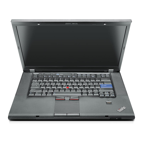
Front view Figure 1. ThinkPad T520, T520i, and W520 front view Computer display Built-in microphone (right) Power switch PCI Express Mini Card slot for wireless WAN or mSATA solid state drive (SSD) PCI Express Mini Card slot for wireless LAN/WiMAX... - Page 21 Your computer might include a PCI Express Mini Card in the PCI Express Mini Card slot which enables wireless WAN communications. With Lenovo technologies advancing to provide you with the best engineered systems, some models are equipped with an mSATA solid state drive for data storage.
- Page 22 Productivity Center program (for Windows XP and Windows Vista Note: Depending on the date when your computer was manufactured, your computer might have the Lenovo ThinkVantage Toolbox program preinstalled instead of the SimpleTap program or the ThinkVantage Productivity Center program.
- Page 23 Bluetooth antenna Your computer has Integrated Bluetooth features. Fn key ® Use the Fn key to take advantage of ThinkPad functions, such as turning on the ThinkLight. To use ThinkPad functions, press Fn+ the required function key marked in blue. CapsLock indicator The indicator of CapsLock is located on the CapsLock key.
-
Page 24: Right-Side View
Right-side view Figure 2. ThinkPad T520, T520i, and W520 right view Security keyhole Ethernet connector Serial Ultrabay enhanced Combo audio jack ExpressCard slot Media card reader slot Security keyhole Your computer comes with a security keyhole. You can purchase a security cable and lock to fit this keyhole. - Page 25 Serial Ultrabay™ enhanced Your computer has a bay for Serial Ultrabay Enhanced devices. An optical drive is installed in the bay. Note: You can install a 9.5-mm-thick serial Ultrabay slim or a 12.7-mm-thick serial Ultrabay enhanced device in the serial Ultrabay enhanced. Combo audio jack To listen to the sound from your computer, connect a headphone or a headset that has a 3.5mm 4-pole plug to the combo audio jack.
-
Page 26: Left-Side View
Left-side view Figure 3. ThinkPad T520, T520i, and W520 left view Fan louvers (left) DisplayPort connector Monitor connector USB connectors (left) USB/eSATA combo connector IEEE 1394 connector Wireless radio switch Smart card slot Fan louvers (left) The internal fan and louvers enable air to circulate in the computer and cool the central processor. - Page 27 • Your computer may look slightly different from the illustrations. • Your computer is compatible with USB 1.1 and 2.0. Some models are also compatible with USB 3.0. • If your computer is a USB 3.0 model, any function specific to USB 3.0 will not work until your Windows operating system has been started.
-
Page 28: Bottom View
Bottom view Figure 4. ThinkPad T520, T520i, and W520 bottom view Battery SIM card slot Docking connector Memory-upgrade slot Hard disk drive (HDD) or solid state drive SIM card slot If your computer has a wireless WAN feature, it may require a SIM (Subscriber Identification Module) card to establish a wireless WAN (Wide Area Network) connections. - Page 29 If you wish, you can purchase another hard disk drive and install it in the serial Ultrabay enhanced. With Lenovo technologies advancing to provide you with the best engineered systems, some models are equipped with a solid state drive for data storage. This cutting-edge technology enables notebook computers to be lighter, smaller and faster.
-
Page 30: Rear View
Rear view Figure 5. ThinkPad T520, T520i, and W520 rear view Modem connector Always On USB connector (rear) Power jack Fan louvers (rear) Always On USB connector (rear) The Universal Serial Bus connectors are used for connecting devices compatible with a USB interface, such as a printer or a digital camera. - Page 31 Fan louvers (rear) The internal fan and louvers enable air to circulate in the computer and cool the central processor. Note: To avoid impeding airflow, do not place any obstacle in front of the fan. Chapter 1 Product Overview...
-
Page 32: Status Indicators
Status indicators Your computer has system-status indicators and power-status indicators. The status indicators show the current status of your computer. System-status indicators Device Access A hard disk drive or an optional drive, such as a drive in the Ultrabay, is being used to read or write data. When this indicator is blinking, do not put the computer into sleep (standby) mode, remove the device from the bay, or turn off the computer. - Page 33 Power-status indicators Sleep (standby in Windows XP) status • Green: The computer is in sleep (standby) mode. • Blinking green: The computer is entering sleep (standby) or hibernation mode, or is resuming normal operation. Battery status • Green: The battery has more than 20% charge. •...
- Page 34 Bluetooth status • Green: The feature is on, and the radio link is ready for use, or the data is being transmitted. • Off: The Bluetooth feature is disabled. Wireless LAN/Wireless WAN/WiMAX status • Green: The wireless LAN feature (the 802.11b/g Standard, 802.11a/b/g or 802.11n draft 2.0), wireless WAN feature or WiMAX feature is on, and the radio link is ready for use, or the data is being transmitted.
-
Page 35: Locating Important Product Information
Certification label, and Windows Certificate of Authenticity. Machine type and model label The machine type and model label identifies your computer. If you contact Lenovo for help, the machine type and model number will help support technicians to identify your computer and provide the highest level of service. -
Page 36: Fcc Id And Ic Certification Number Label
FCC ID and IC Certification number label There is no FCC ID or IC Certification number for the PCI Express Mini Card shown on the enclosure of your computer. The FCC ID and IC Certification number label is affixed on the card installed in the PCI Express Mini Card slot of your computer. -
Page 37: Certificate Of Authenticity Label
Certificate of Authenticity label ® The Microsoft Certificate of Authenticity label for the preinstalled operating system is attached. Printed on this label are the product ID and the product key information for your computer. Record this information and keep it in a safe place. You might need these numbers to start your computer or reinstall the operating system. -
Page 38: Features
(in Windows XP, My Computer); then from the pull down menu select Properties. Memory • Double data rate 3 (DDR3) synchronous dynamic random access memory – ThinkPad T520: 2 slots – ThinkPad T520i: 2 slots – ThinkPad W520: 4 slots Note: For ThinkPad W520 with dual-core processor models, two of the four slots are preinstalled with Dummy DIMM cards. -
Page 39: Specifications
Interface • External monitor connectors (CRT and DisplayPort) • Combo audio jack (stereo headphone or headset) • 3 or 4 Universal Serial Bus connectors (USB 3.0 supported on some models) • 1 Universal Serial Bus/eSATA connector (on some models) • 1 Always On USB connector (on some models) •... -
Page 40: Operating Environment
Do not eat or smoke over your keyboard. Particles that fall into your keyboard can cause damage. ThinkVantage Technologies and software Lenovo preinstalls on your PC useful and helpful software applications to help you get started, to stay productive while on the move and to keep you and your computer working. Lenovo offers enhanced security, wireless computing, data-migration and other solutions for your computer. -
Page 41: Accessing Applications In Windows 7
Note: If you do not find the application you need in Control Panel, open the Lenovo ThinkVantage Tools application navigation window and double-click the dimmed icon to install the application you need. -
Page 42: Access Connections
Lenovo - Fingerprint Reader Hardware and Sound Lenovo - Notebook Fingerprint Reader Lenovo ThinkVantage Toolbox System and Security Lenovo - System Health and Diagnostics Lenovo Solution Center Mobile Broadband Activate Network and Internet Lenovo - 3G Mobile Broadband Password Manager... -
Page 43: Client Security Solution
Note: Depending on the date when your computer was manufactured, your computer is preinstalled with either the Lenovo Solution Center program or the Lenovo ThinkVantage Toolbox program for diagnostic purposes. For additional information about the Lenovo ThinkVantage Toolbox program, see “Lenovo ThinkVantage Toolbox”... -
Page 44: Lenovo Thinkvantage Tools
For detailed information, see “Diagnosing problems” on page 227. To start the Lenovo Solution Center program in Windows 7, see “Accessing applications in Windows 7” on page 23. Lenovo ThinkVantage Tools... -
Page 45: Password Manager
Password Manager The Password Manager program enables users to manage and remember all their sensitive and easy-to-forget application and Web site login information, such as user IDs, passwords, and other personal information. To open Password Manager, do the following: • For Windows 7: See “Accessing applications in Windows 7” on page 23. •... -
Page 46: Simpletap
The ThinkVantage Productivity Center program provides an integrated user interface to help you set up, understand, and enhance your computer. It enables you to access other ThinkVantage Technologies, view messages from Lenovo, and perform the most frequently used tasks such as device configuration, wireless network configuration, and computer management and maintenance. -
Page 47: Chapter 2. Using Your Computer
“Using the media card reader” on page 87 Register your computer When you register your computer, information is entered into a database, which enables Lenovo to contact you in case of a recall or other severe problem. In addition, some locations offer extended privileges and services to registered users. - Page 48 Can I get my user guide in another language? • To download the user guide in another language, go to http://support.lenovo.com. Then follow the instructions on the screen. On the go and need to use battery power more effectively? • To conserve power, or to suspend operation without exiting applications or saving files, see “Power-saving modes”...
-
Page 49: Special Keys And Buttons
Vista). Note: Depending on the date when your computer was manufactured, your computer might have the Lenovo ThinkVantage Toolbox program preinstalled instead of the SimpleTap program or the ThinkVantage Productivity Center program. You also can use the ThinkVantage button to interrupt the startup sequence of your computer and start the... -
Page 50: Numeric Keypad
from it. If the Windows operating system is not running properly, the Rescue and Recovery workspace can help you do the following: • Get the current system information. • Rescue a file from your Windows environment or restore back-up files, provided you have made backups by use of the Rescue and Recovery program. -
Page 51: Function Key Combinations
If the numeric keypad is enabled, press and hold Shift to use the cursor- and screen-control keys temporarily. Note: The functions of the cursor- and screen-control keys are not printed on the keys. Function key combinations By setting the function keys, you can change operational features instantly. To use this function, press and hold the Fn key (1);... - Page 52 Note: If you have logged on with an administrator user ID in Windows XP, and you press Fn+F3, the panel for selecting a power scheme appears. If you have logged on with another user ID in Windows XP, and you press Fn+F3, the panel does not appear. •...
- Page 53 – Computer display and external monitor (LCD + CRT display) – Computer display Notes: – This function is not supported if different desktop images are displayed on the computer display and the external monitor (the Extend desktop function). – This function does not work while a DVD movie or a video clip is playing. –...
-
Page 54: Volume And Mute Buttons
The purpose of this method is to change the brightness level temporarily. On Windows Vista, the default brightness level is loaded after sleep (standby), hibernation, reboot, or detaching or attaching an ac power adapter. To change the default brightness level, change the settings of the Power Option in the Control Panel or use the Power Manager. - Page 55 Setting the volume Each device has volume controls, which you can set. To open the window for adjusting the output volume or the recording volume, do the following: For Windows 7 and Windows Vista: 1. Click Start ➙ Control Panel ➙ Hardware and Sound ➙ Sound. The Sound window appears. 2.
-
Page 56: Windows Key And Application Key
Windows key and Application key The following two keys are on your computer keyboard: Windows key If you press this key, the Start menu of Windows is displayed or hidden. If you press this key and another key at the same time, the System Properties window or the Computer (in Windows XP, My Computer) window is displayed. -
Page 57: Using The Ultranav Pointing Device
Using the UltraNav pointing device Your computer may come with the UltraNav pointing device. The UltraNav consists of the TrackPoint and the touch pad, each of which is itself a pointing device with both basic and extended functions. You can configure both devices by choosing the settings you prefer as follows: •... -
Page 58: Using The Trackpoint Pointing Device
Using the TrackPoint pointing device The TrackPoint pointing device consists of a pointing stick (1) on the keyboard and three click buttons at the bottom of the keyboard. To move the pointer (5) on the screen, you apply pressure to the nonslip cap on the pointing stick in any direction parallel to the keyboard;... -
Page 59: Using The Touch Pad
3. Click the UltraNav tab. Under TrackPoint, proceed to changing the settings. For details, refer to the Help in the Utility. Changing the cap The cap (1) on the end of the TrackPoint pointing stick is removable. You can replace it as shown in the drawing. -
Page 60: Behavior Of The Ultranav And An External Mouse
For details, refer to the Help in the UltraNav. Customizing the touch pad To customize the touch pad, do as follows: 1. Press Fn+F8. A panel for UltraNav Device Settings pops up. 2. Click Manage Settings to open the Mouse properties window. 3. -
Page 61: Touch Panel
1. Press Fn+F8. A panel headed UltraNav Device Settings pops up. 2. Click Manage Settings to open the Mouse properties window. 3. Click the UltraNav tab. 4. Select the check box for Show UltraNav icon on the system tray. 5. Click OK or Apply. 6. -
Page 62: Power Management
Power management When you need to use your computer away from electrical outlets, you depend on battery power to keep your computer running. Different computer components consume power at different rates. The more you use the power-intensive components, the faster you consume battery power. Do more, save more and spend more time unplugged with ThinkPad batteries. -
Page 63: Charging The Battery
Before you charge the battery, make sure that its temperature is at least 10°C (50°F). Charging the battery When you check battery status and find that the percentage of power remaining is low or when the power alarm alerts you that remaining power is low, you need to charge your battery or replace it with a charged battery. - Page 64 Notes: You can also turn off the computer display as follows: 1. Press Fn+F3. A panel for selecting a power plan (in Windows XP, power scheme) appears. 2. Select Fn+F3 Settings. 3. Select Power off display. 4. Click OK. The next time you press Fn+F3, you can turn off the computer display. •...
-
Page 65: Handling The Battery
Do not attempt to disassemble or modify the battery pack. Attempting to do so can cause an explosion, or liquid leakage from the battery pack. A battery pack other than the one specified by Lenovo, or a disassembled or modified battery pack is not covered by the warranty. - Page 66 (2) allow it to heat to more than 100°C (212°F), or (3) attempt to repair or disassemble it. Dispose of it as required by local ordinances or regulations and your company's safety standards. This system does not support batteries that are not genuine Lenovo-made or authorized. The system will continue to boot, but may not charge unauthorized batteries.
-
Page 67: Connecting To The Network
Connecting to the network Your computer has one or more network adapters for connecting to the Internet and to your company's wired LAN or wireless LAN network. Note: Some models come with a built-in wireless WAN card enabling you to establish wireless connections over remote public or private networks. - Page 68 Your computer can be wireless upgradeable. This means that your computer has an antenna that can support wireless LAN access when wireless LAN access points are available. To see more details about the wireless devices available from Lenovo, refer to “Finding ThinkPad options” on page 171. Using wireless WAN connections Wireless Wide Area Network (wireless WAN) enables you to establish wireless connections over remote public or private networks.
-
Page 69: Using Bluetooth
network with the built-in wireless WAN card and the configuration utility to make a wireless WAN connection and monitor its status. Note: Wireless WAN service is provided by authorized service providers in some countries. To find the location of the wireless WAN antenna on your computer, refer to “Location of the UltraConnect wireless antennas”... - Page 70 1. Double-click the My Bluetooth Places icon on the desktop, or the Bluetooth icon in the task bar. The Start Using Bluetooth window opens, and some virtual device drivers are installed automatically. 2. Wait until the installation of the drivers is complete. 1.
- Page 71 • Dial-up networking • Network access • Bluetooth serial port • Bluetooth Imaging • Hands Free • AV profile 4. Click the service you want. For more information, press the F1 key to open the online help for Bluetooth. Bluetooth Configuration To use the configuration features of Bluetooth, right-click the icon.
- Page 72 2. Click Start ➙ Run. 3. Type C:\SWTOOLS\Drivers\TPBTooth\Setup.exe (or specify the full path to the setup.exe file you have downloaded from http://support.lenovo.com); then click OK. 4. Click Next. 5. Select I accept the terms in the license agreement; then click Next.
- Page 73 Using WiMAX Some ThinkPad notebooks come with a built-in wireless LAN card integrating WiMAX technology. WiMAX, a long-range wireless data transmission technology based on the 802.16 standard, provides you with a “last mile” broadband connectivity similar to that offered by cable or ADSL, but without the need to physically connect a cable to the PC.
- Page 74 You can find more detailed information about the signal strength and status of your wireless connection either by opening Access Connections or by double-clicking the Access Connections wireless status icon in the task bar. Note: If your computer is a Windows 7 model, to display the Access Connections status icon and the wireless status icon in the system tray, refer to the Access Connections on-line help.
-
Page 75: Using The Built-In Modem
• You can use the wireless radio switch to disable the wireless radio of all the wireless devices on your computer. • If your computer is a Windows 7 model, to display the Access Connections status icon and the wireless status icon in the system tray, refer to the Access Connections on-line help. -
Page 76: Modem Commands
• Fast Connect Note: This function can work only if the phone line and server equipment at your ISP (Internet Service Provider) access point are compatible with it. Check with your telephone company and ISP. • Modem on Hold Note: This function can be used only in certain countries or regions, because it relies on the specifications of the Call Waiting function and Caller ID function, which each country or region sets independently. - Page 77 Table 3. Modem command list Description Values Command Syntax Z Z Z Z Z Z Reset to default configuration +F +F +FCL CL CLAS AS ASS S S =<Mode> +FCLASS +FCLASS +FCLASS Select Active Service <Mode> Class 0: Select Data Mode 1: Select Facsimile Class 1 Mode 1.0: Select Facsimile Class 1.0...
- Page 78 Table 3. Modem command list (continued) Description Values Command Syntax to the speed buffered normal mode. 4: Select LAPM error-correction mode and forces &Q5 (the modem will try to negotiate an error corrected link). Failure to make an LAPM error-correction connection result in the modem hanging up.
- Page 79 Table 3. Modem command list (continued) Description Values Command Syntax +GMR +GMR +GMR +GMR +GMR +GMR Request Revision Information +GSN +GSN +GSN +GSN +GSN +GSN Request Product Serial Number Identification +GOI I I +GOI +GOI +GOI Request Global Object Identification +GCAP +GCAP +GCAP...
- Page 80 Table 3. Modem command list (continued) Description Values Command Syntax X X X <value> X X X Extended Result Codes <value> 0: CONNECT result code is given upon entering online data state. Dial tone and busy detection reporting are disabled. 1: CONNECT <text>...
- Page 81 Table 3. Modem command list (continued) Description Values Command Syntax &K[<value>] &K &K &K &K &K Flow Control <value> 0: Disables flow control. 3: Enables RTS or CTS flow control. 4: Enables XON or XOFF flow control. 5: Included for compatibility only and has no effect other than returning an OK result code.
- Page 82 Table 3. Modem command list (continued) Description Values Command Syntax D D D <modifier> D D D Dial <modifier> 0 - 9: DTMF digits 0 to 9. A - D: DTMF digits A to D. L: Redial last number. P: Select pulse dialing. T: Select tone dialing.
- Page 83 Table 3. Modem command list (continued) Description Values Command Syntax M M M [<value>] M M M Speaker Control <value> 0: Speaker off. 1: Speaker on during call establishment, but off when receiving carrier. 2: Speaker on. 3: Speaker is off when receiving carrier and during dialing, but on during answering.
- Page 84 Table 3. Modem command list (continued) Description Values Command Syntax +PMHT +PMHT +PMHT=<value> +PMHT +PMHT +PMHT Modem-on-Hold Timer <value> 0: Deny modem-on-hold Request. 1: Grant MOH with 10 sec. timeout. 2: Grant MOH with 20 sec. timeout. 3: Grant MOH with 30 sec. timeout.
-
Page 85: Modem Result Codes
Table 3. Modem command list (continued) Description Values Command Syntax +P +P +PS S S S S S =<value> +PSS +PSS +PSS Use Short Sequence <value> 0: The modem decides whether or not to use the short startup procedures. 1: Reserved. 2: Force the use of the full startup procedures on the next and subsequent connections... - Page 86 Table 4. Modem result codes (continued) Numeric Result code Description 2. If dial tone detection is enforced or selected, dial tone has not been detected. ERROR Sent during an attempt to execute a command line if any of the following conditions occur: 1.
- Page 87 Table 4. Modem result codes (continued) Numeric Result code Description CONNECT 115200 The modem has connected to the line, the DTE speed is 115200 bps, and DTE speed reporting is enabled. CONNECT 75TX/1200RX The modem has established a V.23 originate connection and line speed reporting is enabled.
- Page 88 Table 4. Modem result codes (continued) Numeric Result code Description CONNECT 21600 The modem has connected to the line, the DTE speed is 21600 bps and DTE speed reporting is enabled. CONNECT 24000 The modem has connected to the line, the DTE speed is 24000 bps and DTE speed reporting is enabled.
- Page 89 Table 4. Modem result codes (continued) Numeric Result code Description +MCR: V32 The modem has connected to the line with ITU-T V.32 modulation and modulation reporting is enabled. (See +MR, S95 and Xn.) +MCR: V32B The modem has connected to the line with ITU-T V.32 bis modulation and modulation reporting is enabled.
- Page 90 Table 4. Modem result codes (continued) Numeric Result code Description CONNECT 44000 The modem has connected to the line at 44000 bps and DCE speed reporting is enabled. CONNECT 46000 The modem has connected to the line at 46000 bps and DCE speed reporting is enabled.
- Page 91 Table 4. Modem result codes (continued) Numeric Result code Description +MRR: 28000* The modem has connected to the line at 28000 bps and carrier reporting is enabled. (See S95 and Xn.) +MRR: 29333* The modem has connected to the line at 29333 bps and carrier reporting is enabled.
- Page 92 To change the value of an S register, use the command A A A T T T Sr=n Sr=n where r is a register number 0-110, and Sr=n n is the new value you want to assign. For example, to change the value of S0 register to 20 rings, type ATS0=20 and press Enter.
- Page 93 Table 5. S registers (continued) Register Description Range Units Bit 5 Enable +DR result code (XXXX=compression type). (See +DR.). Bits 6-7 Reserved. Using dialup connection If you sometimes have to dial in to one or more networks from remote sites, such as hotels or offices, you will need to start by setting up in your computer a profile for each site you dial from and a profile for each network you dial in to.
- Page 94 Some countries support pulse dialing rather than tone dialing. To change dialing methods, refer to your Windows online help. Note: In many regions, you cannot use the built-in modem function until Lenovo has received approval from the proper authorities. Your built-in modem is a worldwide modem and can be used in any region where Postal Telegraph and Telephone (PTT) type approval has been obtained.
-
Page 95: Presentations And Multimedia
Presentations and multimedia Your computer comes with many features to increase the enjoyment of your computer and help you give presentations with confidence. Changing display settings You can change the display settings, such as font size or color mode or numeric lock. Font size To make a font size larger, do as follows: For Windows 7:... -
Page 96: Connecting A Projector Or External Display
1. Right-click on the desktop, and click Personalize. 2. Click Display Settings. 3. Click Advanced Settings, select the On Screen Display tab, and then click Num Lock Settings. 4. The setting window opens. 5. Follow the instructions on the screen. For Windows XP: 1. - Page 97 3. If this is the first time the external monitor has been connected, the New Display Detected dialog box opens. Select one of the following, and then click OK. • Duplicate my desktop on all displays (mirrored) • Show different parts of my desktop on each display (extended) •...
- Page 98 12. Clear the Show compatible hardware check box. 13. Select Manufacturer and Model for your monitor. If you cannot find your monitor in the list, stop the installation of this driver and use the driver shipped with your monitor. 14. After updating the driver, click Close. 15.
- Page 99 10. Click the Driver tab. 11. Click Update Driver. The Hardware Update Wizard appears. 12. Click No, not this time, and then click Next. 13. Select Install from a list or specific location (Advanced), and then click Next. 14. Select Don't search. I will choose the driver to install, and then click Next. 15.
-
Page 100: Setting Up A Presentation
3. In the Select a Task navigation pane at left under Display, click Set up multiple displays. 4. In Windows 7 and Windows Vista, right-click on the Verify your display configuration, and then select either the Clone Mode or the Primary. In Windows XP, select a multi-display mode. 5. -
Page 101: Using Dual Displays
You can create a presentation scheme by following the instructions of the Presentation Director, with the projector attached to your computer. You can save the scheme for a future presentation with the same equipment. Playing sound Your projector might have one or more audio-input connectors. To project sound, you will need to attach the combo audio jack on your computer to these connectors, using an audio cable (commercially available). -
Page 102: Using The Nvidia Optimus Graphics Feature
Note: To change the color settings, right-click on the desktop, and click Screen resolution. Click Advanced Settings, select the Monitor tab, then set Colors. For Windows Vista: 1. Connect the external monitor to the monitor connector; then connect the monitor to an electrical outlet. 2. -
Page 103: Using A Color Profile
Note: To use the DisplayPort feature or DVI monitor on the docking station, you need to switch to High Performance Graphics. Switching the Graphics Processing Unit If your computer supports NVIDIA Optimus Graphics, the Graphics Processing Unit is switched automatically depending on the settings of the power plan you use. -
Page 104: Using An Integrated Camera
The following table shows which functions of the audio devices attached to the jacks on your computer or docking station are supported. Table 6. Audio feature list Headset with a 3.5 mm Conventional headphone Conventional microphone 4-pole plug Combo audio jack Headphone and Headphone function Not supported... -
Page 105: Using The Thinklight Feature
Configuring camera settings You can configure the camera settings to meet your needs, such as adjusting the quality of the video output. To configure the camera settings, do the following: 1. Press Fn+F6. The Communications settings window opens. 2. Click the Manage Settings button. The Communication Utility window opens. 3. -
Page 106: Inserting An Expresscard, A Flash Media Card, Or A Smart Card
• SD card • SDHC card • SDXC card • MultiMediaCard (MMC) Notes: • Your computer does not support the CPRM feature for the SD card. • When transferring data to or from a flash media card, such as an SD card, do not put your computer in sleep (standby) or hibernation mode before the data transfer is complete. -
Page 107: Removing An Expresscard, A Flash Media Card, Or A Smart Card
3. Click Device Manager. If you are prompted for an administrator password or confirmation, type the password or provide confirmation. 4. From the Action menu, select Add legacy hardware. The Add Hardware Wizard starts. 5. Follow the instructions on the screen. •... - Page 108 User Guide...
-
Page 109: Copyright Lenovo
By keeping these considerations in mind, you can improve performance and achieve greater comfort. Lenovo is committed to providing the latest information and technology to our customers with disabilities. Refer to our accessibility information which outlines our efforts in this area. -
Page 110: Adjusting Your Computer To Fit You
Note that there are many ThinkPad product solutions available to help you modify and expand your computer to best suit your needs. Access the following Web site to view some of these options: http://www.lenovo.com/accessories/services/index.html. Explore your options for docking solutions and external products that can provide the adjustability and features that you want. -
Page 111: Accessibility Information
Accessibility information Lenovo is committed to providing people with disabilities greater access to information and technology. As a result, the following information provides ways to help users that have hearing, vision, and mobility limitations get the most out of their computer experience. -
Page 112: Traveling With Your Computer
To disable the FullScreen Magnifier function, click the FullScreen Magnifier icon and select Exit or press Fn+Spacebar. Traveling with your computer When you travel abroad, your computer can help you feel more at home and at ease. With your own computer and its files, you can be confident about gathering and offering information to clients and coworkers. - Page 113 • A quality carrying case that provides adequate cushion and protection If you are traveling to another country you might want to consider these items • An ac power adapter for the country that you are traveling to • An adapter to connect to a phone line in that country Other items you may wish to consider •...
- Page 114 User Guide...
-
Page 115: Chapter 4. Security
Refer to the instructions shipped with the mechanical lock. Note: You are responsible for evaluating, selecting, and implementing the locking devices and security features. Lenovo makes no comments, judgments, or warranties about the function, quality, or performance of locking devices and security features. -
Page 116: Passwords And Sleep (Standby) Mode
• “Supervisor password” on page 101 Passwords and sleep (standby) mode If you have set passwords and you put your computer into sleep (standby) mode by pressing Fn+F4, the procedure for resuming operation is as follows: • You are not prompted to type the password when resuming operation. •... -
Page 117: Hard Disk Passwords
Note: You might want to note your power-on password in a safe place. Otherwise, if you forget it, you have to take your computer to a Lenovo reseller or a marketing representative to have the password canceled. 11. Press F10 to exit from the Setup Notice window. - Page 118 Lenovo cannot reset your passwords or recover data from the hard disk. You must take your computer to a Lenovo reseller or a marketing representative to have the hard disk drive replaced. Proof of purchase is required, and a fee will be charged for parts and service.
-
Page 119: Supervisor Password
Setup Notice window is displayed. Press F10 to exit from the Setup Notice window. The user hard disk password will be removed. To change or remove the User + Master hard disk password, select User HDP or Master HDP. If you choose User HDP, do one of the following: •... - Page 120 Attention: You might want to note your password and keep it in a safe place. If you forget your supervisor password, Lenovo can not reset your password. You must take your computer to a Lenovo reseller or a Lenovo marketing representative to have the system board replaced. Proof of purchase is required, and a fee will be charged for parts and service.
-
Page 121: Hard Disk Security
3. Follow step 11 and step 12 above in “Setting a supervisor password” on page 102 to change your supervisor password. To remove the password, do the following: 1. In the Enter Current Password field, type the current supervisor password. 2. -
Page 122: Setting The Security Chip
• For Windows Vista: Click Start ➙ Control Panel ➙ Security ➙ BitLocker Drive Encryption. For details about Windows BitLocker Drive Encryption, go to the Help and Support for Windows 7 or Windows Vista, or search for “Microsoft Windows BitLocker Drive Encryption Step-by-Step Guide” on Microsoft web site. -
Page 123: Using A Fingerprint Reader
Note: If your computer is a Windows 7 model, Client Security Solution is not preinstalled on your system. To configure the security chip, you need to download the latest version of Client Security Solution from the Lenovo Web site. To download Client Security Solution, go to http://support.lenovo.com. Then follow the instructions on the screen. - Page 124 LED behavior of the fingerprint reader Table 7. LED behavior list_fingerprint reader Indicator Description LED blinks green. The fingerprint is being authenticated or has been authenticated. LED is solid green. The fingerprint reader is ready to swipe. LED blinks amber. The fingerprint could not be authenticated.
- Page 125 If you forget your hard disk password, Lenovo cannot reset your password or recover data from the hard disk. You must take your computer to a Lenovo authorized servicer or a marketing representative to have the hard disk drive replaced.
- Page 126 • Reset Fingerprint Data: By choosing this item, you can erase all of the fingerprint data stored in either the internal or external fingerprint reader. To set an item in the fingerprint submenu: 1. Print these instructions. To configure the fingerprint reader, you must turn your computer off and then on again.
-
Page 127: Notice On Deleting Data From Your Hard Disk Drive Or Solid State Drive
• Use the Delete command. • Format your hard disk drive or solid state drive, using the software for initializing it. • Using the recovery program, provided by Lenovo, bring the hard disk drive or the solid state drive back to factory-ship state. - Page 128 Lenovo provides a full version of antivirus software on your computer with a free 30-day subscription. After 30 days, you must renew the license to continue receiving the antivirus software updates. For more information about how to use your antivirus software, refer to the help system of your antivirus software.
-
Page 129: Chapter 5. Recovery Overview
Chapter 5. Recovery overview This chapter provides information about the recovery solutions provided by Lenovo. This chapter contains the following topics: • “Creating and using recovery media” on page 111 • “Performing backup and recovery operations” on page 113 •... -
Page 130: Creating Recovery Media
“creating Product Recovery discs”. • To create recovery media on the Windows 7 operating system, click Start ➙ All Programs ➙ Lenovo ThinkVantage Tools ➙ Factory Recovery Disks. Then, follow the instructions on the screen. -
Page 131: Performing Backup And Recovery Operations
• To perform a backup operation using the Rescue and Recovery program on the Windows 7 operating system, do the following: 1. From the Windows desktop, click Start ➙ All Programs ➙ Lenovo ThinkVantage Tools ➙ Enhanced Backup and Restore. The Rescue and Recovery program opens. -
Page 132: Using The Rescue And Recovery Workspace
1. From the Windows desktop, click Start ➙ All Programs ➙ Lenovo ThinkVantage Tools ➙ Enhanced Backup and Restore. The Rescue and Recovery program opens. 2. In the Rescue and Recovery main window, click the Launch advanced Rescue and Recovery arrow. -
Page 133: Creating And Using A Rescue Medium
• To create a rescue medium on the Windows 7 operating system, do the following: 1. From the Windows desktop, click Start ➙ All Programs ➙ Lenovo ThinkVantage Tools ➙ Enhanced Backup and Restore. The Rescue and Recovery program opens. -
Page 134: Using A Rescue Medium
Using a rescue medium This section provides instructions on how to use the rescue medium you have created. • If you have created a rescue medium using a disc, use the following instructions to use the rescue medium: 1. Turn off your computer. 2. -
Page 135: Solving Recovery Problems
Double-click the file, and follow the instructions on the screen. Attention: If you need updated device drivers, do not download them from the Windows Update Web site. Obtain them from Lenovo. For more information, see “Making sure device drivers are current” on page 222. Solving recovery problems... - Page 136 User Guide...
-
Page 137: Chapter 6. Replacing Devices
• Do not place the part on the computer cover or other metal surface. Replacing the battery Before you start, print these instructions. This system does not support batteries that are not genuine Lenovo-made or authorized. The system will continue to boot, but may not charge unauthorized batteries. © Copyright Lenovo 2012... - Page 138 Attention: Lenovo has no responsibility for the performance or safety of unauthorized batteries, and provides no warranties for failures or damage arising out of their use. To replace the battery with a new one, read the following prerequisites. Prerequisites for the procedure DANGER If the rechargeable battery pack is incorrectly replaced, there is danger of an explosion.
- Page 139 4. Slide the battery into the computer. 5. Slide the battery latch to the locked position. 6. Turn the computer over again. Connect the ac power adapter and the cables to the computer. Using the Extended Life Battery For longer battery life an Extended Life Battery is available as an option. You can attach it to the docking connector of your computer as follows.
- Page 140 3. Align the Extended Life Battery with the bottom side of the computer as shown in the illustration below and firmly attach the battery. 4. Slide the battery latch to the locked position. 5. Turn the computer over again. Connect the ac power adapter and the cables to the computer. To remove the Extended Life Battery, do the following: 1.
- Page 141 3. Unlock the battery latch. 4. Press the latch as shown in the illustration below and detach the battery. 5. Turn the computer over again. Connect the ac power adapter and the cables to the computer. Chapter 6 Replacing devices...
-
Page 142: Replacing The Backup Battery
If the backup battery is incorrectly replaced, there is danger of an explosion. The backup battery contains a small amount of harmful substances. To avoid possible injury: • Replace only with a battery of the type recommended by Lenovo. • Keep the battery pack away from fire. - Page 143 Installing the backup battery under the keyboard 1. Install the backup battery (1). Then attach the connector(2). 2. Reinstall the keyboard. For details, refer to the instructions in “Replacing the keyboard” on page 130. 3. Reinstall the battery. For details, refer to the instructions in “Replacing the battery” on page 119. 4.
-
Page 144: Replacing The Hard Disk Drive
Replacing the hard disk drive Before you start, print these instructions. You can replace the hard disk drive with a new one which can be purchased from your Lenovo reseller or a marketing representative. To replace the hard disk drive, read the following prerequisites. - Page 145 5. Remove the hard disk drive by pulling out the tab. 6. Detach the side rubber rails from the hard disk drive. 7. Attach the side rubber rails to a new hard disk drive. Chapter 6 Replacing devices...
- Page 146 8. Insert the hard disk drive into the slot. 9. Slide the hard disk drive firmly into place. 10. Reinstall the cover of the slot (1), and tighten the screw (2). 11. Reinstall the battery. For details, refer to the instructions in “Replacing the battery” on page 119. User Guide...
- Page 147 12. Turn the computer over again. Connect the ac power adapter and the cables to the computer. Chapter 6 Replacing devices...
-
Page 148: Replacing The Keyboard
Replacing the keyboard Before you start, print these instructions. You can use the following procedures to replace the keyboard with a new one, available as an option. Prerequisites for the procedure DANGER During electrical storms, do not connect the cable to or disconnect it from the telephone outlet on the wall. - Page 149 5. Remove two screws that secure the keyboard. 6. Turn the computer over and open the display. 7. Push hard in the direction shown by the arrows (1) in the drawing to unlatch the front side of the keyboard. The keyboard will open up slightly (2). Chapter 6 Replacing devices...
- Page 150 8. Carefully lift the keyboard until you can see how it's connected. Hold the keyboard above the computer, and then detach the connector (1). Now the keyboard has been removed (2). Installing the keyboard 1. Attach the connector. User Guide...
- Page 151 2. Insert the keyboard. Make sure that the rear edges of the keyboard are under the frame as shown by the arrows. 3. Slide the keyboard as shown by the arrows. 4. Close the computer display, and turn the computer over. Reinstall the two screws. Chapter 6 Replacing devices...
- Page 152 5. Put the memory slot cover back in place (1), close the cover (2), and then tighten the two screws (3). 6. Reinstall the battery. For details, refer to the instructions in “Replacing the battery” on page 119. 7. Turn the computer over again. Connect the ac power adapter and cables to the computer; then turn it on. User Guide...
-
Page 153: Replacing Memory
You can purchase the appropriate memory option from your Lenovo reseller or a marketing representative. Your computer has two memory slots: one under the keyboard and another on the underside of the computer. - Page 154 4. Loosen the two screws on the memory slot cover (1), and then remove the cover (2). If an SO-DIMM is already in the memory slot, remove it to make room for the new one by pressing out on the latches on both edges of the socket at the same time (1). Be sure to save it for future use (2). 5.
- Page 155 6. With the notched end of the SO-DIMM toward the contact edge side of the socket, insert the SO-DIMM into the socket at an angle of about 20 degrees (1); then press it in firmly (2). 7. Pivot the SO-DIMM downward until it snaps into place. 8.
- Page 156 4. Remove the keyboard. For details, refer to the instructions in “Replacing the keyboard” on page 130. 5. If an SO-DIMM is already in the memory slot, remove it to make room for the new one by pressing out on the latches on both edges of the socket at the same time. Be sure to save it for future use. 6.
-
Page 157: Increasing Or Replacing Memory (W520)
10. Reinstall the keyboard. For details, refer to the instructions in “Replacing the keyboard” on page 130. 11. Put the battery back in place (for details, refer to the instructions in “Replacing the battery” on page 119), turn the computer over again, and reconnect the cables. To make sure that the SO-DIMM is installed correctly, do as follows: 1. - Page 158 If you install an SO-DIMM that is not supported by your computer, the computer may beep, and the system may not start or may not work properly. You can purchase the appropriate memory option from your Lenovo reseller or a marketing representative. Increasing memory Your computer has four memory slots: two slots under the keyboard and two on the underside of the computer.
- Page 159 5. Find the notch on the contact edge side of the SO-DIMM you are installing. Attention: To avoid damaging the SO-DIMM, do not touch its contact edge. With the notched end of the SO-DIMM toward the contact edge side of the socket, insert the SO-DIMM into the socket at an angle of about 20 degrees (1);...
- Page 160 If the lower memory slot is empty, proceed to step 5. If both slots are taken, refer to the ThinkPad Web site http://www.lenovo.com/ for more information. 5. For access to the lower slot, you must remove the SO-DIMM already installed in the upper slot. Be sure to keep it.
- Page 161 6. Find the notch on the contact edge side of the SO-DIMM you are installing. Attention: To avoid damaging the SO-DIMM, do not touch its contact edge. With the notched end of the SO-DIMM toward the contact edge side of the socket, insert the SO-DIMM (1) into the lower socket at an angle of about 20 degrees;...
- Page 162 Replacing memory Note: If your computer is a dual-core processor model, two Dummy DIMM cards are preinstalled and do not replace the Dummy DIMM cards with SO-DIMMs. Replacing memory in the slot on the underside of the computer 1. Turn off the computer; then disconnect the ac power adapter and all cables from the computer. 2.
- Page 163 6. Find the notch on the contact edge side of the SO-DIMM you are installing. Attention: To avoid damaging the SO-DIMM, do not touch its contact edge. With the notched end of the SO-DIMM toward the contact edge side of the socket, insert the SO-DIMM into the socket at an angle of about 20 degrees (1);...
- Page 164 1. Turn off the computer; then disconnect the ac power adapter and all cables from the computer. 2. Close the computer display, and turn it over. 3. Remove the battery. For details, refer to the instructions in “Replacing the battery” on page 119. 4.
- Page 165 7. With the notched end of the SO-DIMM toward the contact edge side of the socket, insert the SO-DIMM (1) into the socket at an angle of about 20 degrees; then press it in firmly. Pivot the SO-DIMM downward (2) until it snaps into place. Note: If you install a memory module in only one of the two memory slots, be sure to install it in the upper slot.
-
Page 166: Installing And Replacing The Msata Solid State Drive
Some ThinkPad models have an mSATA solid state drive. You can replace the mSATA solid state drive with a new one which can be purchased from your Lenovo reseller or a marketing representative. To replace the mSATA solid state drive, read the following prerequisites. - Page 167 5. Remove the screw (1). The card pops up (2). 6. Remove the card. Chapter 6 Replacing devices...
- Page 168 7. Align the contact edge of a new mSATA solid state drive with the corresponding socket. Notes: • You can also replace the mSATA solid state drive with a Wireless PCI Express Mini Card for Wireless WAN. • To install a new PCI Express Mini Card, refer to “Installing and replacing the PCI Express Mini Card for wireless WAN connection”...
-
Page 169: Installing And Replacing The Pci Express Mini Card For Wireless Lan/Wimax Connection
Installing and replacing the PCI Express Mini Card for wireless LAN/WiMAX connection Before you start, print these instructions. Your computer has a PCI Express Mini Card slot for connection to a wireless LAN/WiMAX. To replace the PCI Express Mini Card with a new one, read the following prerequisites. Prerequisites for the procedure DANGER During electrical storms, do not connect the cable to or disconnect it from the telephone outlet... - Page 170 5. If a tool for removing connectors is included in the package with the new card, use it to disconnect the cables from the card. If no such tool is included, disconnect the cables by picking up the connectors with your fingers and gently unplugging them. 6.
- Page 171 7. Remove the card. 8. Align the contact edge of the new PCI Express Mini Card with the corresponding socket contact of the computer. Chapter 6 Replacing devices...
- Page 172 Note: If the new PCI Express Mini Card has two connectors, as in the next drawing, put the white cable in the cable protection tube. 9. Pivot the card until you can snap it into place by pressing the upper side of the connectors (1), and secure the card with the two screws (2).
- Page 173 10. Connect the cables to the new PCI Express Mini Card. Be sure to attach the gray cable to the connector marked “MAIN” or “M” on the card, and the black cable to the connector marked “AUX” or “A.” Note: If the new PCI Express Mini Card has three connectors, be sure to attach the gray cable to the connector marked “TR1”...
- Page 174 5. If a tool for removing connectors is included in the package with the new card, use it to disconnect the cables from the card. If no such tool is included, disconnect the cables by picking up the connectors with your fingers and gently unplugging them. 6.
- Page 175 7. Remove the card. 8. Align the contact edge of the new PCI Express Mini Card with the corresponding socket contact of the computer. Chapter 6 Replacing devices...
- Page 176 Note: If the new PCI Express Mini Card has two connectors, as in the next drawing, put the white cable in the cable protection tube. 9. Pivot the card until you can snap it into place by pressing the upper side of the connectors (1), and secure the card with the two screws (2).
- Page 177 10. Connect the cables to the new PCI Express Mini Card. Be sure to attach the gray cable to the connector marked “TR1” on the card, the white cable to the connector marked “RO” or “TR3” (center), and the black cable to the connector marked “TR2”. 11.
-
Page 178: Installing And Replacing The Pci Express Mini Card For Wireless Wan Connection
Installing and replacing the PCI Express Mini Card for wireless WAN connection Before you start, print these instructions. Some ThinkPad models have a PCI Express Mini Card slot for connection to a wireless WAN. To replace the PCI Express Mini Card with a new one, read the following prerequisites. Prerequisites for the procedure DANGER During electrical storms, do not connect the cable to or disconnect it from the telephone outlet... - Page 179 6. Remove the two screws (1). The card pops up (2). 7. Remove the card. Chapter 6 Replacing devices...
- Page 180 8. Align the contact edge of the new PCI Express Mini Card with the corresponding socket. Notes: • You can also replace the PCI Express Mini Card for Wireless WAN with an mSATA solid state drive. • To install a new mSATA solid state drive, refer to “Installing and replacing the mSATA solid state drive”...
- Page 181 10. Connect the cables to the new PCI Express Mini Card. 11. Reinstall the keyboard. For details, refer to the instructions in “Replacing the keyboard” on page 130. 12. Reinstall the battery. For details, refer to the instructions in “Replacing the battery” on page 119. 13.
-
Page 182: Replacing The Sim Card
Replacing the SIM card Before you start, print these instructions. Your computer may require a SIM (Subscriber Identification Module) card to establish a wireless WAN (Wide Area Network) connections. Depending on the country of delivery, the SIM card may be already installed in your computer or will be part of the shipping contents that came with your computer. - Page 183 5. Insert the SIM card firmly into the slot. Note: Make sure that you insert the SIM card all the way into the slot. 6. Put the battery back in place (for more details, refer to “Replacing the battery” on page 119), turn the computer over again, and reconnect the cables.
-
Page 184: Replacing The Solid State Drive
Replacing the solid state drive Before you start, print these instructions. You can replace the solid state drive with a new one which can be purchased from your Lenovo reseller or a marketing representative. To replace the solid state drive, read the following prerequisites. - Page 185 5. Remove the solid state drive by pulling out the tab. 6. Detach the side spacer rails from the solid state drive. 7. Attach the side spacer rails to a new solid state drive. Chapter 6 Replacing devices...
- Page 186 8. Insert the solid state drive into the slot. 9. Slide the solid state drive firmly into place. 10. Reinstall the cover of the slot (1), and tighten the screw (2). 11. Reinstall the battery. For details, refer to the instructions in “Replacing the battery” on page 119. User Guide...
- Page 187 12. Turn the computer over again. Connect the ac power adapter and the cables to the computer. Chapter 6 Replacing devices...
-
Page 188: Replacing The Ultrabay Device
Replacing the Ultrabay device Before you start, print these instructions. To replace the Ultrabay device, do the following. 1. Turn off the computer; then disconnect the ac power adapter and all cables from the computer. 2. Unlock the bay lock latch (1) by sliding it to the top. While holding the bay lock latch in the unlocked position, slide the bay eject latch (2) to the left, then pull out the Ultrabay device (3). -
Page 189: Chapter 7. Enhancing Your Computer
You can shop at Lenovo 24 hours a day, 7 days a week directly over the World Wide Web. All you need is an Internet connection and a credit card. -
Page 190: Performing A Warm Swap
2. Unlock the bay lock latch (1) by sliding it to the top. While holding the bay lock latch in the unlocked position, slide the bay eject latch (2) to the left, then pull out the Ultrabay device (3). 3. Insert the replaceable device into the bay; then press the device firmly into the connector. Note: If a hard disk password is set on a hard disk drive, you cannot hot-swap the drive. - Page 191 1. Unlock the bay lock latch (1) by sliding it to the top. While holding the bay lock latch in the unlocked position, slide the bay eject latch (2) to the left, then pull out the Ultrabay device (3). Note: The computer returns from sleep (standby) mode and the pop-up window appears; then the computer automatically goes into sleep (standby) mode again.
-
Page 192: Inserting The Hard Disk Drive Into The Adapter
2. Insert the replaceable device into the bay; then press the device firmly into the connector. 3. Press the Fn key to return from sleep (standby) mode. Inserting the hard disk drive into the adapter The ThinkPad Serial Hard Drive Bay Adapter III (hard disk drive adapter), which is available as an option, enables you to upgrade the capacity of your computer by installing a secondary hard disk drive. - Page 193 3. Insert the hard disk drive with the label facing upward as shown: Note: If your hard disk drive has a strap, be sure not to leave it under the drive. 4. Connect the hard disk drive to its connector. Chapter 7 Enhancing your computer...
-
Page 194: Inserting The Hard Disk Drive Adapter Into The Bay
5. Close the hard disk drive stopper. Notes: • Make sure that the hard disk drive is inserted tightly into the hard disk drive adapter. • Do not push the cover too hard; you could damage the hard disk drive or the hard disk drive adapter. •... -
Page 195: Thinkpad Port Replicator Series 3, Thinkpad Mini Dock Series 3, Thinkpad Mini Dock Plus Series 3, And Thinkpad Mini Dock Plus Series 3 (170 W)
When you insert the hard disk drive adapter into the bay, make sure that you insert it firmly. If you want to secure your hard disk drive adapter, install a hex-head screw (included in the shipping contents) into the screw hole. ThinkPad Port Replicator Series 3, ThinkPad Mini Dock Series 3, ThinkPad Mini Dock Plus Series 3, and ThinkPad Mini Dock Plus Series 3 (170 W) -
Page 196: Front View
Front view ThinkPad Port Replicator Series 3 The power switch turns the computer on and off. The eject button releases the computer from the ThinkPad Port Replicator Series 3 when pressed. The sliding adjuster is a guide used to align the docking connector on your computer as you attach the ThinkPad Port Replicator Series 3. - Page 197 ThinkPad Mini Dock Series 3 The power switch turns the computer on and off. The key lock indicator lights when the system lock key is in the locked position. When the system lock key is in the locked position, the eject button of the ThinkPad Mini Dock Series 3 is locked; you cannot attach or remove your computer.
-
Page 198: Thinkpad Mini Dock Plus Series 3, And Thinkpad Mini Dock Plus Series
ThinkPad Mini Dock Plus Series 3 and ThinkPad Mini Dock Plus Series 3 (170 W) The power switch turns the computer on and off. The key lock indicator lights when the system lock key is in the locked position. When the system lock key is in the locked position, the eject button of the ThinkPad Mini Dock Plus Series 3 or ThinkPad Mini Dock Plus Series 3 (170 W) is locked;... -
Page 199: Rear View
Rear view ThinkPad Port Replicator Series 3 The power jack is for connecting the ac power adapter. The Ethernet connector is for connecting the ThinkPad Port Replicator Series 3 to an Ethernet LAN. The indicator on the connector is the same as that on the computer. Notes: •... - Page 200 ThinkPad Mini Dock Series 3 The power jack is for connecting the ac power adapter. The DisplayPort is for connecting a display device. The digital visual interface connector is for connecting a monitor that supports Single-Link DVI. Note: The DVI connector provides a digital interface only. This connector can be used with a computer that supports DVI via docking only.
- Page 201 ThinkPad Mini Dock Plus Series 3 and ThinkPad Mini Dock Plus Series 3 (170 W) The DisplayPort is for connecting a display device. The digital visual interface connector is for connecting a monitor that supports Single-Link DVI. Note: The DVI connector provides a digital interface only. This connector can be used with a computer that supports DVI via docking only.
- Page 202 Note: If you attach your computer to the ThinkPad Mini Dock Plus Series 3 or the ThinkPad Mini Dock Plus Series 3 (170 W) and use an external monitor connector, use the external monitor connector on the ThinkPad Mini Dock Plus Series 3 or the ThinkPad Mini Dock Plus Series 3 (170 W), not the one on the computer. When you attach a mechanical lock to the security keyhole, the eject button is locked so that the computer cannot be removed from the ThinkPad Mini Dock Plus Series 3 or the ThinkPad Mini Dock Plus Series 3 (170 W).
-
Page 203: Attaching A Thinkpad Port Replicator Series 3, Thinkpad Mini Dock Series 3, Thinkpad Mini Dock Plus Series 3, Or Thinkpad Mini Dock Plus Series 3 (170 W)
Attaching a ThinkPad Port Replicator Series 3, ThinkPad Mini Dock Series 3, ThinkPad Mini Dock Plus Series 3, or ThinkPad Mini Dock Plus Series 3 (170 W) To attach your computer to a ThinkPad Port Replicator Series 3, a ThinkPad Mini Dock Series 3, a ThinkPad Mini Dock Plus Series 3, or a ThinkPad Mini Dock Plus Series 3 (170 W), do the following: The following drawings are for the ThinkPad Mini Dock Series 3, the ThinkPad Mini Dock Plus Series 3, or the ThinkPad Mini Dock Plus Series 3 (170 W). - Page 204 2. Press the button of the ThinkPad Mini Dock Series 3, the ThinkPad Mini Dock Plus Series 3, or the ThinkPad Mini Dock Plus Series 3 (170 W) (1). Pull the sliding adjuster in the direction shown by the arrow (2). 3.
- Page 205 • If you attach the ThinkPad Port Replicator Series 3, the ThinkPad Mini Dock Series 3, the ThinkPad Mini Dock Plus Series 3, or the ThinkPad Mini Dock Plus Series 3 (170 W) to your computer, but do not connect the ac power adapter of that attachment to the power jack, your computer goes into battery mode.
-
Page 206: Detaching A Thinkpad Port Replicator Series 3, Thinkpad Mini Dock Series 3, Thinkpad Mini Dock Plus Series 3, Or The Thinkpad Mini Dock Plus Series 3 (170 W)
Detaching a ThinkPad Port Replicator Series 3, ThinkPad Mini Dock Series 3, ThinkPad Mini Dock Plus Series 3, or the ThinkPad Mini Dock Plus Series 3 (170 W) To detach your computer from the ThinkPad Mini Dock Series 3, the ThinkPad Mini Dock Plus Series 3, or the ThinkPad Mini Dock Plus Series 3 (170 W), do the following: 1. - Page 207 Notes: • If your computer is operating, make sure that it has finished operations involving devices that are connected to the USB connector. Also make sure that any Ethernet connection is stopped. • Make sure that the battery pack is fully charged. 1.
-
Page 208: Security Feature
Dock Plus Series 3 (170 W), and attach a mechanical lock, the eject button is not locked. To lock the eject button, use the system lock key. Lenovo does not offer a mechanical lock. You will need to purchase one elsewhere. You are responsible for evaluating, selecting, and implementing any locking device and security feature. Lenovo makes no comments, judgments, or warranties about the function, quality, or performance of any locking device or security features. - Page 209 Attach a mechanical lock to the ThinkPad Mini Dock Series 3 as follows: Attach a mechanical lock to the ThinkPad Port Replicator Series 3 as follows: Chapter 7 Enhancing your computer...
-
Page 210: Using The System Lock Key
Using the system lock key The system lock key has two positions, unlocked and locked. When the key is in the locked position, the eject button of the ThinkPad Mini Dock Series 3, the ThinkPad Mini Dock Plus Series 3, or the ThinkPad Mini Dock Plus Series 3 (170 W) is locked, and you cannot remove your computer. -
Page 211: Chapter 8. Advanced Configuration
UEFI/Legacy Boot setting must be the same as it was when the Windows OS image was installed. Or, you will see an error. For the country or region code required in the installation, use one of the following: © Copyright Lenovo 2012... -
Page 212: Installing Windows 7
Note: If you cannot find the Supplement files, device drivers, and application software you need on your hard disk drive, or if you want to receive updates and the latest information about them, go to: http://www.lenovo.com/ThinkPadDrivers Installing Registry Patches for Windows 7 Install the following Registry Patches: •... -
Page 213: Installing Windows Vista
Note: If you cannot find the Supplement files, device drivers, and application software you need on your hard disk drive, or if you want to receive updates and the latest information about them, go to: http://www.lenovo.com/ThinkPadDrivers Chapter 8 Advanced configuration... -
Page 214: Installing Windows Xp
• Registry patch to improve USB device detection on resume from sleep • Fix for Issue of HDD with HD Detection To install these Registry Patches, go to : http://support.lenovo.com Installing the Windows Vista Update Module Package The Windows Vista Update Modules are in the following directory: C:\SWTOOLS\OSFIXES\. - Page 215 ThinkPad Web site at: http://www.lenovo.com/ThinkPadDrivers If you do not have a diskette drive, you can install Intel Rapid Storage Technology Driver by the following...
- Page 216 10. Install Windows XP Service Pack 3. You can install the Windows XP Service Pack 3 using the Windows XP Service Pack 3 Installation CD or download it from either Microsoft Download Center or Microsoft Windows update Web site. 11. Visit the Lenovo Web site at: http://www.lenovo.com/ThinkPadDrivers 12. Download Intel Rapid Storage Technology Driver from the Web site.
-
Page 217: Installing Device Drivers
Installing the driver for 4-in-1 media card reader To use the 4-in-1 media card reader, you need to download and install the Ricoh Multi Card Reader Driver for Windows 7/Vista and Windows XP x86/x64. To download it, go to Lenovo Web site at: http://www.lenovo.com/ThinkPadDrivers Installing the driver for USB 3.0... - Page 218 For Windows 7 1. Right-click on the desktop, and click Personalize. 2. Click Display at the left. 3. Click Change display settings. 4. Click Advanced Settings. 5. Click the Monitor tab. 6. Click Properties. 7. Click the Driver tab. 8. Click Update Driver. 9.
-
Page 219: Thinkpad Setup
3. Click the Advanced tab. 4. Select the Monitor tab. 5. Select Plug and Play Monitor from the monitor type list. 6. Click Properties. 7. Select the Driver tab and click Update Driver. The Hardware Update Wizard starts. 8. Select No, not this time for Windows Update connection, and then click Next. 9. -
Page 220: Config Menu
An example of the ThinkPad Setup menu is shown as below: 4. Using the cursor keys, move to an item you want to change. When the item you want is highlighted, press Enter. A submenu is displayed. 5. Change the items you wish to change. To change the value of an item, press +/-. If the item has a submenu, you can display it by pressing Enter. -
Page 221: Date And Time Menu
Date and time menu If you need to set the current date and time of your computer, select Date/Time from the ThinkPad Setup menu. The following submenu is displayed: • System Date • System Time To change the date and time, do the following: 1. -
Page 222: Startup Menu
• Hard Disk 2 appears on the Password submenu only if a hard disk drive is installed in the serial Ultrabay enhanced. Note: You can install a 9.5-mm-thick serial Ultrabay slim or a 12.7-mm-thick serial Ultrabay enhanced device in the serial Ultrabay enhanced. If you select and enable Hardware Password Manager, you can manage your power-on password, supervisor password, and your hard disk passwords by the management server. - Page 223 3. Press F10 to save the changes and restart the system. To change the startup sequence temporarily so that the system starts up from a different drive, do the following: 1. Turn off the computer. 2. Turn on the computer; then, while the “To interrupt normal startup, press the blue ThinkVantage button” message is displayed at the lower-left of the screen, press F12.
-
Page 224: Restart Menu
Restart menu If you need to close the ThinkPad Setup and restart the system, select Restart from the ThinkPad Setup menu. The following submenu is displayed: • Exit Saving Changes: Restart the system after saving the changes. • Exit Discarding Changes: Restart the system without saving the changes. •... - Page 225 Table 8. Config menu items (continued) Menu item Submenu item Selection Comments USB UEFI BIOS Support • Disabled Enable or disable boot support for USB diskette, • Enabled USB memory key, and USB optical drive. Always On USB • Disabled If you select “Enabled”, the external USB devices can •...
- Page 226 Table 8. Config menu items (continued) Menu item Submenu item Selection Comments Fn Key Lock • Disabled If you select “Enabled”, you can press the Fn key • Enabled to keep it in a pressed condition, and then press the desired function key. The action is equivalent to pressing the required key and the Fn key...
-
Page 227: Windows 7
Table 8. Config menu items (continued) Menu item Submenu item Selection Comments Display Boot Display Device • ThinkPad LCD Select the display device that is to be active at boot • Analog (VGA) time. This selection is • Digital on ThinkPad effective for boot time, password prompt, and •... - Page 228 Table 8. Config menu items (continued) Menu item Submenu item Selection Comments • Balanced Balanced: Balances sound, temperature and performance Note: Each scheme affects fan sound, temperature, and performance. Optical Drive Speed • High Performance Set the speed of optical drive to the desired •...
- Page 229 Table 8. Config menu items (continued) Menu item Submenu item Selection Comments supervisor password. Different beeps will be sounded when the entered password matches or does not match the configured password. Keyboard Beep • Enabled Enable or disable keyboard beep when unmanageable •...
- Page 230 Table 8. Config menu items (continued) Menu item Submenu item Selection Comments If you select “0”, use 60 seconds as default timeout value. If you select “255”, waiting time for establishing a connection is unlimited. Console Type • PC-ANSI Select the console type for AMT.
- Page 231 Table 9. Security menu items (continued) Menu item Submenu item Selection Comments enabled will not be able to work until they are re-enabled in the fingerprint software. • Active Security Chip Security Chip If you select “Active”, Security Chip is functional. •...
- Page 232 Table 9. Security menu items (continued) Menu item Submenu item Selection Comments Memory Protection Execution Prevention • Disabled Some computer viruses and worms cause memory • Enabled buffers to overflow by running code where only data is allowed. If the Data Execution Prevention feature can be used with your operating system, then...
- Page 233 Table 9. Security menu items (continued) Menu item Submenu item Selection Comments ExpressCard Slot • Disabled If you select “Enabled”, you can use the ExpressCard • Enabled Slot. • Disabled If you select “Enabled”, Ultrabay (HDD/Optical) you can use the Ultrabay •...
-
Page 234: Updating Your System Uefi Bios
Startup menu items Table 10. Startup menu items Menu item Selection Comments Boot Refer to “Startup menu” on page 204. Network Boot Refer to “Startup menu” on page 204. UEFI/Legacy Boot • Both Select system boot capability. • UEFI Only •... -
Page 235: Using System Management
To update your UEFI BIOS, go to this Web site at http://www.lenovo.com/ThinkPadDrivers, and follow the instructions on the screen. Using system management This section is intended primarily for network administrators. Your computer is designed for manageability, so that you can redirect more of your resources to better meet your business objectives. -
Page 236: Setting Management Features
Resume on incoming call If your computer is connected to a telephone line and you have specified Resume on incoming call, it will return from sleep (standby) mode to normal operation when a telephone call comes in. To enable your computer to wake up from sleep (standby) mode, do the following: For Windows 7 and Windows Vista: 1. - Page 237 Setting up in the ThinkPad Setup To enable or disable Wake on LAN, go to the ThinkPad Setup menu. When your computer is not under the network administrator's system management, you can disable Wake on LAN. To set this function, do the following: 1.
- Page 238 User Guide...
-
Page 239: Chapter 9. Preventing Problems
9. Profile your machine at http://support.lenovo.com to keep up to date with current drivers and revisions. 10. Keep up to date for device drivers on other non-Lenovo hardware. You might want to read the device driver information release notes prior to updating for compatibility or known issues. -
Page 240: Making Sure Device Drivers Are Current
This may eliminate the driver as the potential cause of the problem. Getting the latest drivers from the Web site You can download and install updated device drivers from the Lenovo Web site by doing the following: 1. Connect to the Internet. - Page 241 Be careful about where and how you work • Store packing materials safely out of the reach of children to prevent the risk of suffocation from plastic bags. • Keep your computer away from magnets, activated cellular phones, electrical appliances, or speakers (within 13 cm or 5 inch).
- Page 242 Take care in setting passwords • Remember your passwords. If you forget a supervisor or hard disk password, Lenovo will not reset it, and you might have to replace your system board, or hard disk drive or solid state drive.
-
Page 243: Cleaning The Cover Of Your Computer
• Your computer might have both an Ethernet connector and a modem connector. If so, be sure to connect your communication cable to the correct one. DANGER To avoid the risk of electrical shock, do not connect the telephone cable to the Ethernet connector. - Page 244 User Guide...
-
Page 245: Chapter 10. Troubleshooting Computer Problems
Note: If you are unable to isolate and repair the problem yourself after running the program, save and print the log files created by the program. You will need the log files when you speak to a Lenovo technical support representative. -
Page 246: Troubleshooting
Note: If you are unable to isolate and repair the problem yourself after running the program, save and print the log files created by the program. You will need the log files when you speak to a Lenovo technical support representative. -
Page 247: Spills On The Keyboard
4. While the computer is off, remove all sources of power and external hardware. Refer to the procedure in “Replacing memory” on page 135 on how to remove and reseat the memory modules. Remove any non-original memory module added to your computer. After removing the extra memory module and reseating the original memory module, repeat step 2. - Page 248 • Message: 0188: Invalid RFID Serialization Information Area Solution: The EEPROM checksum is not correct (block # 0 and 1). The system board should be replaced, and the box serial number needs to be reinstalled. Have the computer serviced. • Message: 0189: Invalid RFID configuration information area Solution: The EEPROM checksum is not correct (block # 4 and 5).
-
Page 249: Errors Without Messages
Solution: The hard disk is not working. Have the hard disk serviced. • Message: 2101: Detection error on HDD1 (Ultrabay HDD) Solution: The hard disk is not working. Have the hard disk serviced. • Message: 2102: Detection error on HDD2 (Mini SATA) Solution: The Mini SATA device is not working. -
Page 250: Beep Errors
• Problem: When I turn on the machine, nothing appears on the screen and the machine does not beep while starting up. Note: If you are not sure whether you heard any beeps, turn off the computer by pressing and holding the power switch for 4 seconds or more. -
Page 251: Memory Problems
Memory problems Print these instructions now and keep it with your computer for reference later. If your memory is not operating properly, check the following items: 1. Verify that the memory is installed and seated correctly in your computer. It may be necessary to remove all added memories to test the computer with only the factory-installed memories, and then reinstall the memory one at a time to ensure a proper connection. - Page 252 5. Click Properties. 6. Click the Change settings button. If you are prompted for an administrator password or confirmation, type the password or provide confirmation. 7. Click the Modem tab. 8. Clear the Wait for dial tone before dialing check box. 9.
- Page 253 If the task tray has no icon for the MoH application, start the application as follows: 1. Click Start. 2. Click All Programs ➙ NetWaiting ➙ NetWaiting. If the icon for the application is on the task tray, make sure that the function is enabled as follows: 1.
-
Page 254: Ethernet Problems
Ethernet problems • Problem: Your computer cannot connect to the network. Solution: Make sure that: – The cable is installed properly. The network cable must be securely connected both to the Ethernet connector of your computer and to the RJ45 connector of the hub. The maximum allowable distance from the computer to hub is 100 meters. -
Page 255: A Wireless Lan Problem
Solution: – Make sure that WOL is enabled in the ThinkPad Setup. – If it is, check with your LAN administrator for the necessary settings. • Problem: If your computer is a Gigabit Ethernet model, it cannot connect to the network at 1000 Mbps. Instead, it connects at 100 Mbps. - Page 256 Solution: Windows 7 and Windows Vista send PIM items in XML format, but most Bluetooth-enabled devices handle PIM items in vCard format. If another Bluetooth-enabled device can receive a file through Bluetooth, a PIM item sent from Windows 7 and Windows Vista might be saved as a file with the extension .contact.
- Page 257 • Problem: You cannot send a business card to the connected computer. Solution: Make sure that your computer has its own default business card application and that the card is ready for communication. Make sure that the security settings on the connected computer allow you to upload your business card. •...
-
Page 258: Keyboard And Other Pointing Devices
7. Check whether the words “Bluetooth Device” appear in the device listing in the window. If the words “Bluetooth Radio” appear in the device listing, the Microsoft Bluetooth software is installed on your computer. If you want to use ThinkPad Bluetooth with Enhanced Data Rate Software, you have to install it and then replace the Bluetooth driver. -
Page 259: Display And Multimedia Devices
If the keyboard problem is resolved, carefully reconnect the external numeric keypad, external keyboard, making sure that you have seated the connectors properly. If the problem remains, make sure that the correct device driver is installed. For Windows 7: 1. Click Start ➙ Control Panel. Change the view of the Control Panel from Category to Large icons or Small icons. - Page 260 Solution: Make sure that: – The display device driver is installed correctly. – The screen resolution and color quality are correctly set. – The monitor type is correct. To check these settings, do as follows: For Windows 7: 1. Right-click on the desktop, and click Personalize. 2.
-
Page 261: External Monitor Problems
6. Make sure that the correct device driver name is shown in the adapter information window. Note: The device driver name depends on the video chip that has been installed on your computer. 7. Click the Properties button. Check the “Device status” box and make sure the device is working properly. - Page 262 5. Make sure that the correct device driver name is shown in the adapter information window. Note: The device driver name depends on the video chip that has been installed on your computer. 6. Click OK. If the information is incorrect, reinstall the device driver. See below for more information. For Windows Vista: 1.
- Page 263 12. Clear the Show compatible hardware check box. 13. Select Manufacturer and Model for your monitor. 14. After updating the driver, click Close. 15. Set Resolution. Note: To change the color settings, select the Monitor tab, then set Colors. 16. Click OK. For Windows Vista: 1.
- Page 264 8. If more than one monitor type is displayed, select Default Monitor. 9. Click Properties. 10. Click the Driver tab. 11. Click Update Driver. The Hardware Update Wizard appears. 12. Click No, not this time, and then click Next. 13. Select Install from a list or specific location (Advanced), and then click Next. 14.
- Page 265 1. Connect the external monitor to the monitor connector, and then connect the monitor to an electrical outlet. 2. Turn on the external monitor and the computer. 3. Press Fn+F7 to change the display output location to the external monitor. Note: After pressing Fn+F7, you will need to wait for a moment before the image appears.
-
Page 266: Audio Problems
9. Select the Resolution and Colors of the secondary display. 10. Set the relative position of the each monitor by dragging its icon. You can set the monitors in any relative position, but the icons must touch each other. 11. Click OK to apply the changes. For Windows XP: 1. - Page 267 Solution: Make sure the built-in audio device is configured correctly. For Windows 7 and Windows Vista: 1. Click Start ➙ Control Panel. 2. Click Hardware and Sound. 3. Click Device Manager. If you are prompted for an administrator password or confirmation, type the password or provide confirmation.
- Page 268 Solution: The slider might be grayed out. This means that its position is fixed by the hardware and cannot be changed. • Problem: The volume sliders do not stay in place when some audio applications are used. Solution: It is normal for the sliders to change position when certain sound applications are used. The applications are aware of the Volume Mixer window (in Windows XP, Volume Control window) and are allowed to change the settings themselves.
-
Page 269: Fingerprint Reader Problems
• Problem: When you connect a headphone to your computer while playing sound, a speaker does not produce sound in the MULTI-STREAM mode at SmartAudio (Windows 7). Solution: Once the headphone is attached, the streaming is automatically redirected to it. If you want to listen to sound from the speakers again, be sure to set those speakers as the default device. -
Page 270: Power Problems
1. Turn off the computer. 2. Make sure that the over-discharged battery pack is in the computer. 3. Connect the ac power adapter to the computer and let it charge. If the optional Quick Charger is available, use it to charge the over-discharged battery pack. If the battery pack cannot be fully charged in 24 hours, use a new battery pack. -
Page 271: A Power Button Problem
4. Verify the ac power source is working by attaching another device to the outlet. 5. Remove the computer from a ThinkPad Port Replicator Series 3, ThinkPad Mini Dock Series 3, ThinkPad Mini Dock Plus Series 3, or ThinkPad Mini Dock Plus Series 3 (170 W). Refer to “Detaching a ThinkPad Port Replicator Series 3, ThinkPad Mini Dock Series 3, ThinkPad Mini Dock Plus Series 3, or ThinkPad Mini Dock Plus Series 3 (170 W)”... - Page 272 If you receive an error message while the operating system is loading the desktop configuration after the POST is completed, check the following items: 1. Go to the Lenovo Support Web site at http://support.lenovo.com and search for the error message. 2. Go to the Microsoft Knowledge Base homepage at http://support.microsoft.com/ and search for the error message.
-
Page 273: Drives And Other Storage Devices
Solution: Check whether any option has been selected to disable your computer from entering sleep (standby) or hibernation mode. If your computer tries to enter sleep (standby) mode but the request is rejected, the device in the USB connector might be disabled. If this occurs, do a hot-unplug-and-plug operation for the USB device. •... -
Page 274: Solid State Drive Problems
Solid state drive problems • Problem: When you compress files or folders by use of the data compression function in Windows, and then decompress them, the process of writing to or reading from the files or folders is slow. Solution: Apply the disk defragmentation tool in Windows for faster access to the data. Optical drive problems •... -
Page 275: Software Problems
4. Click the Recording tab. 5. Clear the check box for Enable CD recording on this drive. 6. Click OK. You can get detailed information from the More Information section of the Microsoft Knowledge Base 826510. Visit the Microsoft Knowledge Base homepage at http://support.microsoft.com/, type the number of the knowledge base article you need in the search field, and click the Search button. - Page 276 Universal Serial Bus problems • Problem: A device connected to the USB connector does not work. Solution: Open the Device Manager window. Make sure that the USB device setup is correct, and that the assignment of computer resource and the installation of the device driver are correct. For Windows 7 and Windows Vista: 1.
-
Page 277: Chapter 11. Getting Support
Register your computer Register your ThinkPad products with Lenovo. Go to: http://www.lenovo.com/register. This can help authorities return your computer to you if it is lost or stolen. Registering your computer also enables Lenovo to notify you about possible technical information and upgrades. -
Page 278: Getting Help And Service
Lenovo to assist you. This section contains information about where to go for additional information about Lenovo and our products, what to do if you experience a problem with your computer, and whom to call for service should it be necessary. -
Page 279: Purchasing Additional Services
• Lenovo hardware repair - If the problem is determined to be caused by Lenovo hardware under warranty, trained service personnel are available to provide the applicable level of service. • Engineering change management - Occasionally, there might be changes that are required after a product has been sold. - Page 280 User Guide...
-
Page 281: Appendix A. Regulatory Information
Usage environment and your health Integrated wireless cards emit radio frequency electromagnetic energy like other radio devices. However, the level of energy emitted is far much less than the electromagnetic energy emitted by wireless devices like for example mobile phones. © Copyright Lenovo 2012... -
Page 282: Location Of The Ultraconnect Wireless Antennas
Due to the fact that integrated wireless cards operate within the guidelines found in radio frequency safety standards and recommendations, Lenovo believes they are safe for use by consumers. These standards and recommendations reflect the consensus of the scientific community and result from deliberations of panels and committees of scientists who continually review and interpret the extensive research literature. -
Page 283: Locating Wireless Regulatory Notices
For more information about the wireless regulatory notices, refer to the ThinkPad Regulatory Notice shipped with your computer. If your computer is shipped without the Regulatory Notice, go to the Lenovo Web site at http://www.lenovo.com/ThinkPadUserGuides. Then follow the instructions on the screen to find the Regulatory Notice. -
Page 284: Federal Communications Commission Declaration Of Conformity
• Consult an authorized dealer or service representative for help. Lenovo is not responsible for any radio or television interference caused by using other than specified or recommended cables and connectors or by unauthorized changes or modifications to this equipment. -
Page 285: German Class B Compliance Statement
Geräte der Klasse B. Dieses Gerät ist berechtigt, in Übereinstimmung mit dem Deutschen EMVG das EG-Konformitätszeichen - CE - zu führen. Verantwortlich für die Konformitätserklärung nach Paragraf 5 des EMVG ist die Lenovo (Deutschland) GmbH, Gropiusplatz 10, D-70563 Stuttgart. Informationen in Hinsicht EMVG Paragraf 4 Abs. (1) 4: Das Gerät erfüllt die Schutzanforderungen nach EN 55024 und EN 55022 Klasse B. -
Page 286: Lenovo Product Service Information For Taiwan
Lenovo product service information for Taiwan User Guide... -
Page 287: Appendix B. Weee And Recycling Statements
Collecting and recycling a disused Lenovo computer or monitor If you are a company employee and need to dispose of a Lenovo computer or monitor that is the property of the company, you must do so in accordance with the Law for Promotion of Effective Utilization of Resources. -
Page 288: Battery Recycling Information For Brazil
If you want to replace it with a new one, contact your place of purchase or ask for a repair service provided by Lenovo. If you have replaced it by yourself and want to dispose of the disused lithium battery, insulate it with vinyl tape, contact your place of purchase, and follow their instructions. -
Page 289: Battery Recycling Information For European Union
For proper collection and treatment, go to: http://www.lenovo.com/lenovo/environment Battery recycling information for United States and Canada Appendix B. WEEE and recycling statements... - Page 290 User Guide...
-
Page 291: Appendix C. Notices
Lenovo representative for information on the products and services currently available in your area. Any reference to a Lenovo product, program, or service is not intended to state or imply that only that Lenovo product, program, or service may be used. Any functionally equivalent product, program, or service that does not infringe any Lenovo intellectual property right may be used instead. -
Page 292: Trademarks
Trademarks The following terms are trademarks of Lenovo in the United States, other countries, or both: Lenovo Access Connections Active Protection System Rescue and Recovery ThinkLight ThinkPad ThinkVantage TrackPoint Ultrabay UltraConnect UltraNav Intel and Intel SpeedStep are trademarks or registered trademarks of Intel Corporation or its subsidiaries in the United States and other countries. -
Page 293: Appendix D. Restriction Of Hazardous Substances Directive (Rohs)
Appendix D. Restriction of Hazardous Substances Directive (RoHS) China RoHS Turkish RoHS The Lenovo product meets the requirements of the Republic of Turkey Directive on the Restriction of the Use of Certain Hazardous Substances in Electrical and Electronic Equipment (EEE). Ukraine RoHS © Copyright Lenovo 2012... -
Page 294: India Rohs
India RoHS RoHS compliant as per E-Waste (Management & Handling) Rules, 2011. User Guide... - Page 296 Part Number: (1P) P/N:...
- Page 297 *1P*...