Table of Contents
Advertisement
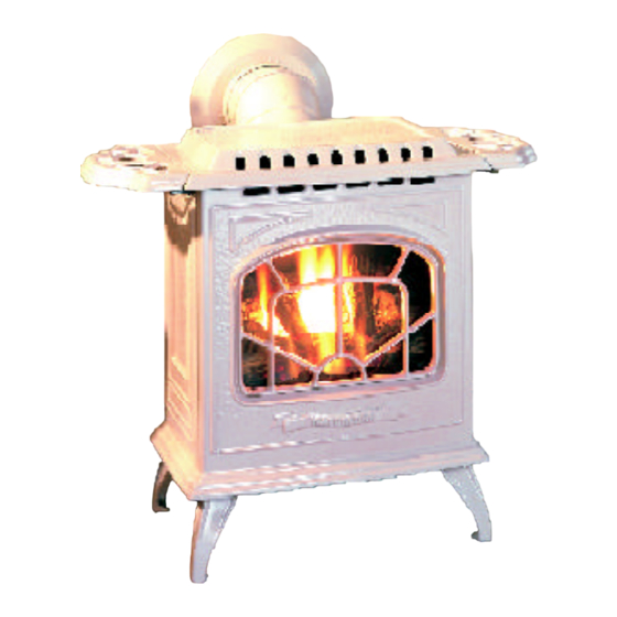
TARA Direct Vent Freestanding Gas Stove
WARNING:
If the information in these instructions are not followed exactly,
a fire or explosion may result causing property damage,
personal injury or loss of life.
FOR YOUR SAFETY
Do not store or use gasoline or other flammable vapors and
liquids in the vicinity of this or any other appliance.
Installation and service must be performed by a qualified
installer, service agency or the gas supplier.
Tested by:
FPI FIREPLACE PRODUCTS INTERNATIONAL LTD. 6988 Venture St., Delta, BC Canada, V4G 1H4
908-788a
www.waterfordstoves.com
MODELS: T25-NG Natural Gas T25-LP Propane
Installer: Please complete the details on the back cover
and leave this manual with the homeowner.
Homeowner: Please keep these instructions for future reference.
Owners &
Installation Manual
FOR YOUR SAFETY
What to do if you smell gas:
Do not try to light any appliance
Do not touch any electrical switch:
do not use any phone in your
building.
Immediately call your gas supplier
from a neighbour's phone. Follow
the gas supplier's instructions.
If you
cannot reach your gas
supplier, call the fire department.
01/09/06
Advertisement
Table of Contents

Related Manuals for Waterford TARA T25-LP


Summary of Contents for Waterford TARA T25-LP
- Page 1 www.waterfordstoves.com Owners & TARA Direct Vent Freestanding Gas Stove Installation Manual MODELS: T25-NG Natural Gas T25-LP Propane WARNING: FOR YOUR SAFETY If the information in these instructions are not followed exactly, What to do if you smell gas: a fire or explosion may result causing property damage, Do not try to light any appliance personal injury or loss of life.
- Page 2 WATERFORD TARA Direct Vent Freestanding Gas Stove To the New Owner: Congratulations! You are the owner of a state-of-the-art Waterford Direct Vent Freestanding Gas Stove by Waterford Irish Stoves. The Waterford Gas Series of hand crafted appliances has been designed to provide you with all the warmth and charm of a woodstove, at the flick of a switch.
-
Page 3: Table Of Contents
TABLE OF CONTENTS Page Page Converting a Factory Built Metal Chimney ....22 Safety Label High Elevation ............23 System Data Chart ..........24 Safety Labels ............4 Gas Connection ........... 24 Gas Pipe Pressure Testing ........24 Installation Valve Description ..........24 Valve Conversion to Propane ......... -
Page 4: Safety Labels
SAFETY LABEL This is a copy of the label that accompanies NOTE: Waterford units are constantly being here for your review. The safety label is located each TARA Direct Vent Freestanding Gas improved. Check the label on the unit and if on the inside of the drop down pedestal door. -
Page 5: Installation
INSTALLATION IMPORTANT: This Direct Vent System Appliance must be OF THE APPLIANCE BE KEPT installed in accordance with the manufactur- CLEAN. SAVE THESE er's installation instructions and the Manufac- tured Home Construction and Safety Standard, INSTRUCTIONS Title 24 CFR, Part 3280, or the current Standard DUE TO HIGH TEMPERATURES, of Fire Safety Criteria for Manufactured Home THE APPLIANCE SHOULD BE LO-... -
Page 6: Manufactured Mobile Home Requirements
INSTALLATION specified vent and termination cap to the Thermostat. Some areas may have further ments, pages 9 to 20. Minimum Horizontal outside of the building envelope. Never vent requirements, check local codes before Vent Kit, page 11, Vertical Termination Co- to another room or inside a building. -
Page 7: Locating Your Tara Gas Stove
INSTALLATION Use the minimum clearances shown in the 3) Remove the Top Control Panel Assembly by diagrams below: removing the three screws. TARA Clearances Side Wall to Unit* A 6" / 150 mm Back Wall to Unit B 3" / 75 mm Unit Corner to Wall C 2"... - Page 8 INSTALLATION 9) Connect the red wire from the thermodisc to the red wire of 11) Slide the thermodisc into the bracket clip on the underside of the the speed control wire harness. firebox. 10) Connect the live black wire from power cord to the black wire of the speed control wire harness.
-
Page 9: Venting Introduction
INSTALLATION SAFETY INSTALLATION VENTING PRECAUTIONS FOR PRECAUTIONS INTRODUCTION THE INSTALLER These venting systems are engineered prod- The following vent systems in combination with ucts that have been designed and tested for the Tara Direct Vent Freestanding Gas Stove, 1) Wear gloves and safety glasses for pro- use with the Tara. -
Page 10: Exterior Vent Terminal Locations
INSTALLATION EXTERIOR VENT TERMINAL LOCATIONS Waterford TARA T25 Direct Vent Freestanding Gas Stove... -
Page 11: Minimum Horizontal Termination
INSTALLATION RESIDENTIAL AND MANUFACTURED HOMES / MOBILE HOMES MINIUMUM HORIZONTAL TERMINATION INSTALLATIONS You will require the following components with your new Regency Rear Vent Direct Vent Planning Your venting Installation Freestanding Gas Stove. Please review your product to make sure you have everything you need. In the event that you are missing any part, contact your dealer. - Page 12 INSTALLATION HORIZONTAL *Dia 2a & 2b: As speci- fied in CGA B149 Instal- INSTALLATIONS lation Code. Local codes or regulations may re- quire different clearanc- 1) Set the unit in its desired location. Check to determine if wall studs are in the way when the venting system is attached.
-
Page 13: Vertical Termination With Co-Linear Flex System
INSTALLATION c) Before connecting the vent pipe to the vent VERTICAL TERMINATION WITH termination, slide the black decorative wall CO-LINEAR FLEX SYSTEM thimble cover over the vent pipe, then slide the Wall Penetration Heat Shield (Part # 946-202) over the vent pipe. Dia. 3. THE APPLIANCE MUST NOT BE d) Slide the appliance and vent assembly CONNECTED TO A CHIMNEY FLUE... -
Page 14: Dv Stove Horizontal Vent Kit And Installation
INSTALLATION DV STOVE HORIZONTAL VENT KIT DV Stove Horizontal Vent Kit (2 ft. Part # 946-116 or 4 ft. Part # 946-216) includes all the parts needed to install the U29-2 or U45-3 with minimum horizontal and vertical vent dimensions. For installations that require longer vertical and/or horizontal vents use the Dura-Vent system as shown on page 18. -
Page 15: Dura-Vent Termination Kits
INSTALLATION 14) Secure the 4" dia. flex liner with adapter onto the stove collar. Put a bead of Mill-Pac around the appliance adapter and secure with 3 screws (#8 x 1/2, stainless steel). 15) Attach the 45 elbow onto the starter collar by sealing with Mill-Pac and/or high tem- perature silicone and securing with 3 of the #8 x 1/2"... -
Page 16: Installation
INSTALLATION from the rear of the unit to the wall. It is also ments from decks, windows, soffits, gas reg- above the roof line. important to note the wall thickness. (The wall ulators, air supply inlets and public walkways thimble is suitable for 2 x 4 or 2 x 6 wall as specified in the Exterior Vent Terminal For multi-storey applications, fire stops are construction.) Select the amount of vertical rise... -
Page 17: Rigid Pipe Venting Components List
INSTALLATION RIGID PIPE VENTING COMPONENTS LIST All Simpson Dura-Vent components are available directly from FPI. Description Simpson Dura-Vent Selkirk Amerivent Direct VentGS Direct-Temp Direct Vent 6" Pipe Length, Galvanized 4DT-6 6" Pipe Length, Black 908B 4DT-6B 7" Pipe Length, Galvanized 7"... -
Page 18: Rigid Pipe Venting
INSTALLATION RIGID PIPE VENTING - HORIZONTAL TERMINATIONS The shaded area in the diagram below shows all allowable combinations of vertical runs with horizontal terminations. Maximum one 90 elbow (two 45 elbows equal one 90 elbow) using Dura-Vent Venting Systems Residential and Manufactured Homes / Mobile Homes Installations The venting arrangements diagrammed below, have a minimum of 75% (flue loss) efficiency with Fan Off, as required for manufactured homes. -
Page 19: Vent Restrictor
INSTALLATION Standoff to the Horizontal Vent Termination, VENT RESTRICTOR Note: but first run a bead of non-hardening mastic a) Twist-lock procedure: Four indenta- around its outside edges, so as to make a tions, located on the female ends of The above Offset to Vertical Installation re- seal between vent cap and the standoff. -
Page 20: Dura-Vent Vertical Installation
INSTALLATION Secure the connection between the vent 6) Continue to assemble pipe lengths. pipe and the vent cap by attaching the two sheet metal strips extending from the vent Note: If an offset is necessary in the attic cap assembly into the outer wall of the vent to avoid obstructions, it is impor- pipe. -
Page 21: Offset Chart
INSTALLATION b) Any occupied areas above the first Support Extensions - Round floor, including closets and storage (RDSE) or Square (SQSE) spaces, through which the vertical vent passes, must be enclosed. Steep pitched cathedral ceilings may require the use of a support extension. This piece fits down inside the support and can be adjusted to in- crease the support's length by up to 22". -
Page 22: Converting A Factory Built Metal Chimney
INSTALLATION 3) Connect the end of the The direct vent system must not be con- 7) The connection between the appliance and flex pipe section to the nected to a damaged factory-built or ma- the Retro Connector may be completed underside of the Top sonry chimney. -
Page 23: High Elevation
INSTALLATION HIGH ELEVATION This unit is approved in Canada for altitude to 4500 ft. (CAN/CGA-2.17-M91) with the resized orifice. For Natural Gas installations above 4500 ft. follow current CAN/CGA-B149.1. In U.S.A., for installations above 2000 ft. refer to current ANSI Z223.1 Sc8-8.1.2a appendix F, for resizing orifice. -
Page 24: System Data Chart
INSTALLATION GAS CONNECTION Valve Description Recommended Gas Pipe Diameter Pipe Schedule 40 Tubing, 1) Gas cock knob Length Pipe Type L The gas connection is a 3/8" NPT 90 elbow. The 2) Manual high/low adjustment (feet) Inside Diameter Outside Diameter gas line can be rigid pipe or to make installation 3) Pilot Adjustment easier, use a listed flexible connector and/or... - Page 25 INSTALLATION 7) Pull off the pilot cap to expose the pilot the stove's rear heat shield to indicate that NOTE: If the conversion to Propane is orifice. the unit has been converted to burn pro- being made at the time of installation, pane.
-
Page 26: Aeration Adjustment
INSTALLATION 8) Using the 1/4" nut driver or flat screwdriv- AERATION er, tighten the locking screw on the burner ADJUSTMENT air shutter. 9) Replace the log set, glass panel and Cast The burner aeration is factory set but may need Iron Front Panel. -
Page 27: Optional Side Shelf
INSTALLATION 5) Place the middle log on the 2 middle log pins. OPTIONAL LOG INSTALLATION SIDE SHELF WARNING: Dangerous operating con- ditions may occur if these logs are not Contents: positioned in their approved locations. Qty. Side Shelf Read the instructions below carefully Side Shelf Bracket and refer to the diagrams. -
Page 28: Optional Remote Control Installation
INSTALLATION The remote control kit comes with a hand held FINAL CHECK Thermostat Wire Table transmitter, a receiver and a wall mounting plate. Recommended Maximum Lead Length Before leaving this unit with the customer, the (Two-Wire) When Using Wall installer must ensure that the appliance is firing 1) Choose a convenient location on the wall to Thermostat (CP-2 System) correctly. -
Page 29: Operating Instructions
OPERATING INSTRUCTIONS 4) When the pilot stays lit, turn the gas knob turing. Smoke detectors in the house may go off OPERATING further counterclockwise to the "ON" posi- at this time. Open a few windows to ventilate INSTRUCTIONS tion. the room for a couple of hours. 5) Use the thermostat or remote control to turn The glass panel may require cleaning after the 1) Read and understand these instructions... -
Page 30: Copy Of Lighting Plate Instructions
OPERATING INSTRUCTIONS COPY OF THE NORMAL OPERATING LIGHTING PLATE INSTRUCTIONS SOUNDS OF GAS APPLIANCES It is possible that you will hear some sounds from your gas appliance. This is perfectly normal due to the fact that there are various gauges and types of steel used within your appliance. -
Page 31: Maintenance
MAINTENANCE Incorrect flame pattern will have small, probably MAINTENANCE WARNING: CHILDREN AND yellow flames, not coming into proper contact ADULTS SHOULD BE ALERTED INSTRUCTIONS with the rear of the burner or thermopile. TO THE HAZARDS OF HIGH SUR- FACE TEMPERATURE 1) Always turn off the valve before cleaning. -
Page 32: Glass Replacement
MAINTENANCE VALVE MAINTENANCE GLASS 5) Insert the glass (with gasket) in to the frame so that the 'bulb' portion of the gasket is REPLACEMENT exposed. If your valve requires maintenance or replace- ment, use the following instructions. 6) Using a flat screwdriver, close the 4 retain- Your TARA stove is supplied with high temper- ing tabs used to hold the glass in place. -
Page 33: Replacement Parts List
PARTS LIST REPLACEMENT / SPARE PARTS LIST Part # Description W260021** Front Casting (Black) 280-022 Door W260040/P Glass 41225 Gasket for Glass 904-012 Capscrew 1/4 x 1-3/4 NC 260350 Gasket for Rear Relief Plate 290-015 Rear Blow Off Plate 280-020 Rear Panel 260-037 Rear Control Panel... - Page 34 NOTES _ _ _ _ _ _ _ _ _ _ _ _ _ _ _ _ _ _ _ _ _ _ _ _ _ _ _ _ _ _ _ _ _ _ _ _ _ _ _ _ _ _ _ _ _ _ _ _ _ _ _ _ _ _ _ _ _ _ _ _ _ _ _ _ _ _ _ _ _ _ _ _ _ _ _ _ _ _ _ _ _ _ _ _ _ ____________________________________________________________ __________________________________________________________ ____________________________________________________________...
-
Page 35: Warranty
WARRANTY Waterford Fireplace Products are designed with reliability and simplicity in mind. In addition, our internal Quality Assurance Team carefully inspects each unit thoroughly before it leaves our facility. FPI Fireplace Products International Ltd. is pleased to extend this limited lifetime warranty to the original purchaser of a Waterford Product. - Page 36 Waterford fireplace products are designed with reliability and simplicity in mind. In addition, our internal Quality Assurance Team carefully inspects each unit thoroughly before it leaves our door. Waterford Irish Stoves is pleased to extend this Limited Lifetime Warranty to the original purchaser of a Waterford Product.