Table of Contents
Advertisement
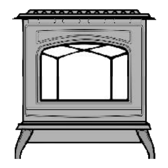
EMERALD Direct Vent Freestanding Gas Stove
WARNING:
If the information in these instructions are not followed exactly,
a fire or explosion may result causing property damage,
personal injury or loss of life.
FOR YOUR SAFETY
Do not store or use gasoline or other flammable vapors and
liquids in the vicinity of this or any other appliance.
Installation and service must be performed by a qualified
installer, service agency or the gas supplier.
Tested by:
908-805a
FPI FIREPLACE PRODUCTS INTERNATIONAL LTD. 6988 Venture St., Delta, BC Canada, V4G 1H4
www.waterfordstoves.com
MODELS:
E65-NG1 Natural Gas
Installer: Please complete the details on the back cover
and leave this manual with the homeowner.
Homeowner: Please keep these instructions for future reference.
Installation Manual
E65-LP1 Propane
FOR YOUR SAFETY
What to do if you smell gas:
Do not try to light any appliance
Do not touch any electrical switch:
do not use any phone in your
building.
Immediately call your gas supplier
from a neighbour's phone. Follow
the gas supplier's instructions.
If you cannot reach your gas
supplier, call the fire department.
Owners &
01/09/06
Advertisement
Table of Contents

Related Manuals for Waterford EMERALD E65-LP1


Summary of Contents for Waterford EMERALD E65-LP1
- Page 1 www.waterfordstoves.com Owners & EMERALD Direct Vent Freestanding Gas Stove Installation Manual MODELS: E65-NG1 Natural Gas E65-LP1 Propane WARNING: FOR YOUR SAFETY If the information in these instructions are not followed exactly, What to do if you smell gas: Do not try to light any appliance a fire or explosion may result causing property damage, Do not touch any electrical switch: personal injury or loss of life.
- Page 2 WATERFORD EMERALD Direct Vent Freestanding Gas Stove To the New Owner: Congratulations! You are the owner of a state-of-the-art Waterford Direct Vent Freestanding Gas Stove by Waterford Irish Stoves. The Waterford Gas Series of hand crafted appliances has been designed to provide you with all the warmth and charm of a woodstove, at the flick of a switch. The models E65-NG1 and E65-LP1 of this series have been approved by Warnock Hersey for both safety and efficiency.
-
Page 3: Table Of Contents
TABLE OF CONTENTS Page Page Safety Label Support Extension - Round or Square ....... 22 Converting a Class-A Metal Chimney or Masonry Safety Labels ............4 Chimney to a Direct Vent System ...... 22 System Data Chart ..........24 Installation High Elevation ............ -
Page 4: Safety Labels
SAFETY LABEL This is a copy of the label that accompanies here for your review. The safety label is NOTE: Waterford units are constantly being each EMERALD Direct Vent Freestanding Gas located on the inside of the drop down pedestal improved. -
Page 5: Safety Label
SAFETY LABEL Copy of Safety Label for E65-LP1 Propane Stove For the State of Massachusetts, installation and repair must be done by a plumber or gasfitter licensed in the Commonwealth of Massachusetts. For the State of Massachusetts, flexible connectors shall not exceed 36 inches in length. -
Page 6: Installation
INSTALLATION This Direct Vent System Appliance must be IMPORTANT: THE CONTROL COMPARTMENT, installed in accordance with the manufacturer's BURNERS AND CIRCULATING AIR SAVE THESE installation instructions and the Manufactured PASSAGEWAYS OF THE APPLI- Home Construction and Safety Standard, Title INSTRUCTIONS 24 CFR, Part 3280, or the current Standard of ANCE BE KEPT CLEAN. -
Page 7: General Safety Information
INSTALLATION pages 11 and 12 for the required vent 8) Any safety glass removed for servicing CLEARANCES TO arrangements. If installed into a manufac- must be replaced prior to operating the COMBUSTIBLES tured home the unit must be bolted down to appliance. -
Page 8: Locating Your Emerald Gas Stove
INSTALLATION LOCATING YOUR OPTIONAL FAN INSTALLATION EMERALD GAS STOVE Fan Kit Contains: 7) Install locking grommet to power cord and push through hole in the rear panel and give When selecting a location for your stove, en- Qty. Description a 1/4 turn to secure. sure that the clearances listed above are met as Fan Speed Controller with nut, and knob. -
Page 9: Venting Introduction
INSTALLATION VENTING INSTALLATION VENT RESTRICTORS INTRODUCTION #1 AND #2 PRECAUTIONS The Horizontal Termination Kit and the Simpson These venting systems are engineered prod- Vent restrictors are required for certain venting Dura-Vent Direct Vent System Model DV-GS installations, see the diagrams on pages 12 and ucts that have been designed and tested for venting systems, in combination with the Emer- 13 to determine if they are required for your... -
Page 10: Exterior Vent Terminal Locations
INSTALLATION EXTERIOR VENT TERMINAL LOCATIONS Waterford E65-1 Emerald Direct Vent Freestanding Gas Stove... -
Page 11: Rigid Pipe Venting Components List
INSTALLATION RIGID PIPE VENTING COMPONENTS LIST All Simpson Dura-Vent components are available directly from FPI. Description Simpson Dura-Vent Selkirk Amerivent Direct VentGS Direct-Temp Direct Vent 6" Pipe Length, Galvanized 4DT-6 6" Pipe Length, Black 908B 4DT-6B 7" Pipe Length, Galvanized 7"... -
Page 12: Rigid Pipe Venting - Horizontal Terminations
INSTALLATION RIGID PIPE VENTING - HORIZONTAL TERMINATIONS The shaded area in the diagram below shows all allowable combinations of vertical runs with horizontal terminations. Maximum one 90 elbow (two 45 elbows equal one 90 elbow), not including the 45 elbow attached to the unit. RESIDENTIAL AND Manufactured Homes / Mobile Homes Installations The venting arrangements diagrammed below, have a minimum of 75% (flue loss) efficiency with Fan Off, as required for manufactured homes. -
Page 13: Rigid Pipe Venting - Vertical Terminations
INSTALLATION RIGID PIPE VENTING - VERTICAL TERMINATIONS FOR BOTH RESIDENTIAL & MANUFACTURED HOMES/MOBILE HOMES The shaded areas in the two diagrams below show all allowable combinations of straight vertical and offset to vertical runs with vertical terminations. Maximum two 45 elbows, not including the 45 elbow attached to the unit. -
Page 14: Vertical Termination With Co-Linear Flex System
INSTALLATION VERTICAL TERMINATION WITH CO-LINEAR FLEX SYSTEM Masonry chimneys may take various contours which the flexible liner will accommodate. THE APPLIANCE MUST NOT BE However, keep the flexible liner as straight as possible , avoid unnecessary bending. CONNECTED TO A CHIMNEY FLUE SERVING A SEPARATE SOLID FUEL The Air Intake pipe must be attached to the inlet air collar of the termination cap. -
Page 15: Minimum Horizontal Termination Kit
INSTALLATION MINIUMUM HORIZONTAL TERMINATION INSTALLATIONS See page 10 for Exterior Vent Termination requirements. The E65 is approved for a minimum horizontal termination with the Regency Riser Vent Kit. See the diagram on page 13 for minimum and maximum pipe lengths. When planning your installation, it will be necessary to select the proper length of vent pipe for your particular requirements. -
Page 16: Horizontal Termination Kit Installation
INSTALLATION DV STOVE HORIZONTAL VENT KIT (# 946-116 & #946-216) INSTALLATION Review the following sequence of instructions which are typical of most installations. The sequence may vary depending on wall thick- ness. Refer to pages 10 to 14 for vent location and clearance dimensions. -
Page 17: Dura-Vent Termination Kits
INSTALLATION temperature silicone and secure with 3 of point, stainless steel). Note: pilot holes will the unit flue outlet to the ceiling, the ceiling the #8 x 1/2" screws (black). Pipe seams need to be drilled through the wall thimble thickness, the vertical rise in an attic or second facing down. -
Page 18: Installation
INSTALLATION You will require the following components with Minimum components for a Dura-Vent If installing termination on a siding covered wall, your new Emerald Direct Vent Freestanding Horizontal Installation: a vinyl siding standoff or furring strips can be Gas Stove. Please review your product to used in order to ensure that the termination is make sure you have everything you need. -
Page 19: Dura-Vent Horizontal Installation
INSTALLATION DURA-VENT HORIZONTAL INSTALLATIONS 1) Set the unit in its desired location. Check to c) Snorkel Terminations: horizontal pipe, as shown in diagram 3. Cut determine if wall studs or roof rafters are For installations requiring a vertical rise and frame the 10 inch square hole in the in the way when the venting system is on the exterior of the building, 14-inch exterior wall where the vent will be termi-... -
Page 20: Dura-Vent Vertical Termination Installation
INSTALLATION 3) To install the Round Support Box/Wall Thim- not recessed into the siding. The 8) Slide the decorative wall thimble up to the ble in a flat ceiling, cut a 10 inch square hole f o u r w o o d s c r e w s p r o v i d e d wall surface being careful not to scratch in the ceiling centred on the hole drilled in should be replaced with appro-... -
Page 21: Offset Chart
INSTALLATION roofline. The galvanized finish is desirable above the roofline due to its higher corro- sion resistance. Continue to add pipe sections through the flashing until the height of the vent cap meets the minimum height requirements specified in diagram 11 or local codes. Note that for steep roof pitches, the vertical height must be increased. -
Page 22: Support Extension - Round Or Square
INSTALLATION 3) Connect the end of Support Extensions - Round The direct vent system must not be con- the flex pipe section nected to a damaged factory-built or ma- (RDSE) or Square (SQSE) to the underside of sonry chimney. the Top Adaptor us- Steep pitched cathedral ceilings may require the ing 3 sheet metal For factory built, zero clearance, and ma-... - Page 23 INSTALLATION Converting a Masonry Chimney Important: The existing masonry flue opening needs to have an area of at least a 36 sq. in. to insure proper intake/ex- haust flow. 1) Before cutting any holes, assemble the desired sections of black direct vent pipe to determine the center of the masonry pene- tration.
-
Page 24: System Data Chart
INSTALLATION Note: Prior to any pressure testing of SYSTEM DATA - E65-1 SYSTEM DATA - the gas supply piping system that (WITH 38,000 BTU) E65-1 CONVERTED TO exceeds test pressures of 1/2 27,000 (NATURAL GAS) psig, this appliance must be dis- connected from the piping sys- For 0 to 2000* feet altitude OR 29,000 (PROPANE) -
Page 25: Gas Pipe Pressure Testing
INSTALLATION GAS PIPE PRESSURE TESTING The appliance must be isolated from the gas supply piping system by closing its individual manual shut-off valve during any pressure testing of the gas supply piping system at test pressures equal to or less than 1/2 psig. (3.45 kPa). -
Page 26: Reduction For Lower Btu Rating
INSTALLATION 6) Remove and discard the 3 pressure regu- REDUCTION KIT TO lator mounting screws (A), pressure reg- LOWER BTU RATING ulator tower (B) and diaphragm (C). FOR E65-1 GAS STOVE 7) Insure that the rubber gasket (D) is properly positioned and install the new HI/LO pres- sure regulator assembly to the valve using HIS CONVERSION MUST... -
Page 27: Log Installation
INSTALLATION LOG INSTALLATION 4) Carefully remove the logs, embers and rock- wool. WARNING: Dangerous operating condi- 5) Remove burner. tions may occur if these logs are not positioned in their approved locations. Read the instructions below carefully and refer to the diagrams. If logs are broken do not use the unit until they are replaced. -
Page 28: Optional Wall Thermostat
INSTALLATION 2) Remove the glass panel by loosening the 6 OPTIONAL REMOTE screws securing the glass brackets. Sup- CONTROL port the glass to prevent it from dropping out and breaking. Use the Waterford Remote Control Kit approved for this unit. Use of other systems may void your warranty. -
Page 29: Wiring Diagram - E65-Ng1 & E65-Lp1
OPERATING INSTRUCTIONS WIRING DIAGRAM - E65-NG1 & E65-LP1 If any of the original wires as supplied with the Caution: Ensure that the wires do WARNING: Electrical Grounding appliance must be replaced, it must be replaced Instructions not touch any hot surfaces and are with CSA type SEW (200 C) or its equivalent. -
Page 30: Shutdown Procedure
OPERATING INSTRUCTIONS pilot does not remain lit, repeat operation Copy of the Lighting Plate instructions allowing a longer period before releasing gas control knob. 4) When the pilot stays lit, turn the gas knob further counterclockwise to the "ON" posi- tion. -
Page 31: Convection Fan Operation
MAINTENANCE 6) The appliance and venting system must be AUTOMATIC Burner Tray: inspected before use, and at least annual- The burner tray is positioned directly under the CONVECTION FAN ly, by a qualified field service person, to burner tube(s) and logs and is made of a ensure that the flow of combustion and different gauge material from the rest of the OPERATION... -
Page 32: General Vent Maintenance
MAINTENANCE across the rear of the burner (it does not LOG REPLACEMENT WARNING: Do not operate appli- have to be touching the burner). ance with glass panels removed, cracked or broken. Replacement of Note: If you have an incorrect flame pat- The unit should never be used with broken logs. -
Page 33: Removing And Installing Valve
MAINTENANCE 10) Remove all 18 screws holding the burner REMOVING VALVE IMPORTANT tray assembly in place. Disconnect power supply If your valve requires maintenance or replace- before servicing ment, use the following instructions: Note: Always close off the gas supply To remove fan: before removing the valve. -
Page 34: Replacement Parts List
PARTS LIST MAIN ASSEMBLY Part # Description Part # Description Part # Description W400141** Emerald Right Door (Black) W841991** Emerald Hob (Black) 923R Direct Vent Connector 904-258 Door Magnet Nut - 1/4 - 20 Hex 936-194 Gasket - Starter Collar/Air 948-134 Door Stop 42801... - Page 35 PARTS LIST BURNER & LOG ASSEMBLY Part # Description 910-190 Piezo Ignitor & Nut 908-672 Control Panel Decal 490-061 Switch Plate 910-896 High Temperature Wire Harness - to Power Cord 261-574/P Valve Assembly S.I.T. - Natural Gas 261-576/P Valve Assemlby S.I.T. - Propane 261-969 Conversion to Propane Kit 910-378...
- Page 36 NOTES _ _ _ _ _ _ _ _ _ _ _ _ _ _ _ _ _ _ _ _ _ _ _ _ _ _ _ _ _ _ _ _ _ _ _ _ _ _ _ _ _ _ _ _ _ _ _ _ _ _ _ _ _ _ _ _ _ _ _ _ _ _ _ _ _ _ _ _ _ _ _ _ _ _ _ _ _ _ _ _ _ _ _ _ _ ____________________________________________________________ __________________________________________________________ ____________________________________________________________...
- Page 37 NOTES _ _ _ _ _ _ _ _ _ _ _ _ _ _ _ _ _ _ _ _ _ _ _ _ _ _ _ _ _ _ _ _ _ _ _ _ _ _ _ _ _ _ _ _ _ _ _ _ _ _ _ _ _ _ _ _ _ _ _ _ _ _ _ _ _ _ _ _ _ _ _ _ _ _ _ _ _ _ _ _ _ _ _ _ _ ____________________________________________________________ __________________________________________________________ ____________________________________________________________...
- Page 38 NOTES _ _ _ _ _ _ _ _ _ _ _ _ _ _ _ _ _ _ _ _ _ _ _ _ _ _ _ _ _ _ _ _ _ _ _ _ _ _ _ _ _ _ _ _ _ _ _ _ _ _ _ _ _ _ _ _ _ _ _ _ _ _ _ _ _ _ _ _ _ _ _ _ _ _ _ _ _ _ _ _ _ _ _ _ _ ____________________________________________________________ __________________________________________________________ ____________________________________________________________...
-
Page 39: Warranty
WARRANTY Waterford Fireplace Products are designed with reliability and simplicity in mind. In addition, our internal Quality Assurance Team carefully inspects each unit thoroughly before it leaves our facility. FPI Fireplace Products International Ltd. is pleased to extend this limited lifetime warranty to the original purchaser of a Waterford Product. - Page 40 Waterford fireplace products are designed with reliability and simplicity in mind. In addition, our internal Quality Assurance Team carefully inspects each unit thoroughly before it leaves our door. Waterford Irish Stoves is pleased to extend this Limited Lifetime Warranty to the original purchaser of a Waterford Product.