Table of Contents
Advertisement
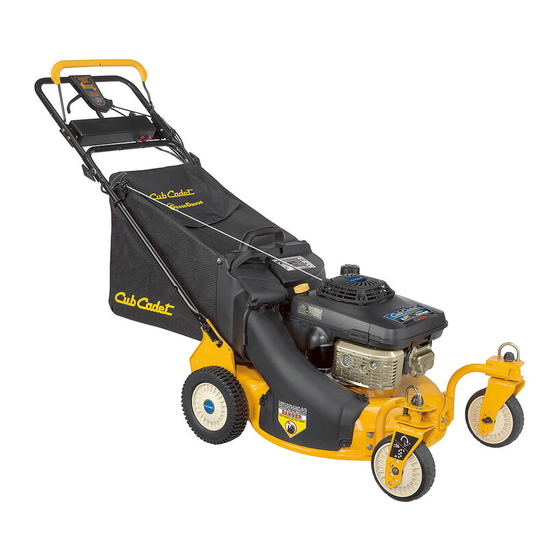
Operator's Manual
21" Self-Propelled
Mower
Model 997
IMPORTANT: Read safety rules and instructions carefully
Warning:
This unit is equipped with an internal combustion engine and should not be used on or near any unimproved forest-covered,
brush-covered or grass-covered land unless the engine's exhaust system is equipped with a spark arrester meeting applicable local or state
laws (if any). If a spark arrester is used, it should be maintained in effective working order by the operator. In the State of California the
above is required by law (Section 4442 of the California Public Resources Code). Other states may have similar laws. Federal laws apply
on federal lands. A spark arrester for the muffler is available through your Cub Cadet dealer or contact the service department, P.O. Box
361131 Cleveland, Ohio 44136-0019.
Cub Cadet LLC., P.O. Box 361131, Cleveland, Ohio 44136-0019
PRINTED IN U.S.A.
770-10090E.fm
Form No.
(12/2002)
Advertisement
Chapters
Table of Contents
Troubleshooting

Related Manuals for Cub Cadet 997


Summary of Contents for Cub Cadet 997
- Page 1 (Section 4442 of the California Public Resources Code). Other states may have similar laws. Federal laws apply on federal lands. A spark arrester for the muffler is available through your Cub Cadet dealer or contact the service department, P.O. Box 361131 Cleveland, Ohio 44136-0019.
-
Page 2: Table Of Contents
(Model Number) (Serial Number) Copy the model number here: Copy the serial number here: CUB CADET LLC P. O. BOX 361131 www.cubcadet.com CLEVELAND, OH 44136 DEALER LOCATOR PHONE NUMBER: 877-282-8684... -
Page 3: Important Safe Operation Practices
SECTION 1: IMPORTANT SAFE OPERATION PRACTICES WARNING: This symbol points out important safety instructions which, if not followed, could endanger the personal safety and/or property of yourself and others. Read and follow all instructions in this manual before attempting to operate this machine. Failure to comply with these instructions may result in personal injury. -
Page 4: Slope Operation
immediately and the blade will stop rotating within 3. Do not mow on wet grass. Unstable footing could three seconds. cause slipping. 9. Mow in daylight or good artificial light; walk, not run. Children 10. Stop the blade when crossing gravel drives, walkways or roads. - Page 5 10. Never over fill fuel tank. Fill tank to no more than ½ 4. Mower blades are sharp and can cut. Wrap the inch below bottom of filler neck to provide space for blade or wear gloves, and use extra caution when fuel expansion.
-
Page 6: Slope Gauge
SECTION 2: SLOPE GAUGE Use this page as a guide to determine slopes where you may not operate safely. Do not operate your lawn mower on such slopes. -
Page 7: Assembling Your Lawn Mower
SECTION 3: ASSEMBLING YOUR LAWN MOWER Removing Unit From Carton Setting Up Your Lawn Mower • Remove staples, break glue on top flaps, or cut Assembling Handle tape at carton end and peel along top flap to open • Lift up and pull back on the upper handle to raise carton. - Page 8 • Fasten the cable to the lower handle with the two cable ties found on the lower handle. Pull the cable Grass Bag Adapter ties tight and trim off the excess. See Figure 5. Cable Tie Lower Handle Wing Nuts Figure 5 Figure 7 Attaching Starter Rope...
-
Page 9: Know Your Lawn Mower
SECTION 4: KNOW YOUR LAWN MOWER Read this operator’s manual and safety rules before Drive Clutch Control operating your lawn mower. Compare the illustration in The drive clutch control is located on the upper handle. Figure 10 with your lawn mower to familiarize yourself Squeeze the drive control to engage the drive system. -
Page 10: Operating Your Lawn Mower
SECTION 5: OPERATING YOUR LAWN MOWER WARNING: Be sure no one other than the WARNING: Read, understand, and follow all operator is standing near the lawn mower while instructions and warnings on the machine and starting engine or operating mower. in this manual before operating. -
Page 11: Making Adjustments
thrown by the mower in any direction and cause serious • Attach grass catcher following instructions on page 8 of this manual. Grass clippings will automatically personal injury to the operator and others. collect in the bag as you run the mower. •... -
Page 12: Engine Adjustments
The front wheel cutting height is determined by Bottom View selecting one of six positions on each caster assembly. To adjust front cutting height, proceed as follows: • Remove the wing nut from the axle bolt. See Figure Upper 13. Slide the axle bolt and spring washer from the Adjustment Handle assembly and select a cutting height. -
Page 13: Maintaining Your Lawn Mower
SECTION 7: MAINTAINING YOUR LAWN MOWER • Inspect muffler periodically, and replace if WARNING: Always stop the engine and necessary. Damaged mufflers or spark arresters disconnect the spark plug wire before can create a fire hazard. Make sure to avoid muffler performing any maintenance work or and surrounding areas while the mower engine is adjustments on your lawn mower. -
Page 14: Blade Care
SECTION 8: SERVICING THE MOWER • Place the blade on the adapter. Be certain the WARNING: Always stop the engine and blade is aligned and seated on the blade adapter disconnect the spark plug wire before flanges. performing any maintenance work or •... - Page 15 • Remove the hex bolt from the rear of unit holding • Pivot the control arm down away from the pulley the transmission to the mower housing. and belt. See Figure 19. • Lift off the lower pulley assembly and remove the old belt from around the crankshaft.
-
Page 16: Replacing Battery Pack
• Attach the new flap and new rod to deck, bending the ends of the new rod over to secure to deck. Six-Speed Cable Slot Replacing Battery Pack (Model E977 only) • Remove the battery pack from the handle panel for replacement only. -
Page 17: Troubleshooting
SECTION 10: TROUBLESHOOTING Problem Cause Remedy Engine fails to start Blade control handle disengaged. Engage blade control handle. Spark plug wire disconnected. Connect wire to spark plug. Fuel tank empty or stale fuel. Fill tank with clean, fresh gasoline. Blocked fuel line. Clean fuel line. - Page 18 YOUR NOTES Date Comments...
- Page 19 Safety & Decorative Labels Some of the labels found on your mower are representeted here with the corresponding part numbers. Please use these part numbers when ordering replacement labels. 777S30118 777I20291 777S30128 777S30116 AVOID SERIOUS INJURY OR DEATH • KEEP HANDS AND FEET AWAY FROM ROTATING PARTS.
-
Page 20: Parts List
SECTION 11: PARTS LIST FOR MODEL 997 36 37 47 57 IMPORTANT: proper working machine, use Factory Approved Parts. V-BELTS are specially designed to engage and disengage safely. A substitute (non OEM) V-Belt can be dangerous by not disengaging completely. - Page 21 Model 997 Ref. Part No. Description Ref. Part No. Description 647-00408 Control Handle 736-0270 Bell Washer .265 ID x .75 OD 731-0904A Upper Control Handle 710-0751 Hex Cap Screw 1/4-20 x .620 16864 6 Spd. Rack Cable Bracket 737-3000 Grease Fitting 731-0620 Control Lever 736-0931...
- Page 22 Model 997...
- Page 23 Model 997 Ref. Ref. Part No. Part Description Part No. Part Description 720-0223 Grip 712-0896 Hex Jam Nut 1/4-28 732-0803A Spring Lever 782-7598 Belt Keeper 738-0529 Shoulder Nut .825 x .165 Lg. 741-0600 Bearing 710-0751 Cap Screw 1/4-20 x .620 732-0849A Extension Spring 736-0270...
-
Page 24: Kawasaki Engine Manual
Engine Manual for Kawasaki Engine SAFETY AWARENESS WARNING: Whenever you see the symbols shown on the left, heed their instructions! Always follow safe operating and maintenance practices. FORWARD We wish to thank you for purchasing this Kawasaki engine. Please read this Owner's manual carefully before starting your new engine so that you will be thoroughly familiar with the proper operation of your engine's control, its features, capabilities and limitations. -
Page 25: Emission Control Information
READ THIS FIRST WARNING: Never allow children to operate the engine or equipment. Keep people and pets out of area where you are using the engine or equipment. Never wear loose, torn, or bulky clothing. It may catch on moving parts or controls, leading to the risk of accident. - Page 26 gasses are led to a breather chamber through the necessary to ensure compliance with the applicable crankcase and from there to the air cleaner. standards. Engine Emissions Compliance Period As the owner of the engine, you have the responsibility to make sure that the recommended maintenance is California carried out according to the instructions in this Owner's Model Year - 2006 and later Vertical Crankshaft...
-
Page 27: General Information
General Information Location of Safety Related Labels Figure 3 A. Fuel Tank Cap B. Fuel Tank (capacity 2.0L [0.528US gal.]) Figure 1 C. Fuel Tube a. Warning (Refer to ) D. Carburetor b. Engine Maintenance (Refer to )) E. Priming Pump F. -
Page 28: Fuel And Oil Recommendations
Fuel And Oil Recommendations Fuel Use only clean, fresh, unleaded regular grade < SAE5W-20 > gasoline. Octane Rating < SAE5W-20 > The octane rating of a gasoline is a measure of its resistance to "knocking".Use a minimum of 87 octane of <... -
Page 29: Starting
• Remove the oil gauge to check the oil level. Level damage to the recoil starter or pad system of should be between "ADD" and "FULL" marks. Do the engine. not overfill. • DO NOT pull the recoil starter grip out of the •... -
Page 30: Adjustment
Adjustment A. Brake Control Lever B. Handle Engine Speed Adjustment NOTE: Do not tamper with the governor setting or the carburetor setting to increase the engine speed. Each carburetor is adjusted at the factory with either a cap or stop plate installed on the mixture screw. Any adjustments must performed... -
Page 31: Air Cleaner Service
Air Cleaner Service • Remove the oil drain plug (A) on side of the engine or on bottom of the engine to drain oil into suitable CAUTION: To prevent excessive engine wear, do container (B) while the engine is warm. not run the engine with the air cleaner WARNING: Clean the elements in a well-... -
Page 32: Spark Plug Service
CAUTION: Do not oil foam element. • Check the spark plug gap and reset it if necessary. The gap must be between 0.7 and 0.8 mm (0.028 Paper Element and 0.032"). • Clean the paper element every 100 hours. To change the gap, bend only the side-electrode, using •... -
Page 33: Troubleshooting Guide
• Remove the spark plug and pour approx. 1-2 mL A. Spark Plug Hole (0.06-0.1 cu.in) of new engine oil through the plug • Slowly pull the recoil starter grip until you feel hole (A), slowly pull the recoil starter grip several compression and leave it there. -
Page 34: Specifications
Specifications Type of Engine Air-cooled, 4-stroke OHV, single cylinder, gasoline Engine • Bore X Stroke • 65 x 54mm (2.6 x 2.1 in.) • Displacement • 179mL (109. cu.in.) • Ignition system • Solid-state ignition • Starting system • Recoil starter •... - Page 35 listed here.) These warranted parts are: carburetor and internal parts, spark advance/retard system. cold start enrichment system, magneto or electronic ignition system, catalytic converter, intake manifold, exhaust manifold, air cleaner element, and spark plugs if failure occurs prior to the first required scheduled replacement, hoses, clamps, fittings, gaskets, sealing devices, mounting hardware and tubing used directly in these parts.
- Page 36 MANUFACTURER’S LIMITED WARRANTY FOR: The limited warranty set forth below is given by Cub Cadet Cub Cadet LLC does not extend any warranty for LLC with respect to new merchandise purchased and used in products sold or exported outside of the United States, the United States, its possessions and territories.