Table of Contents
Advertisement
Available languages
Available languages
Operator's Manual
CP.RFTSMRN°
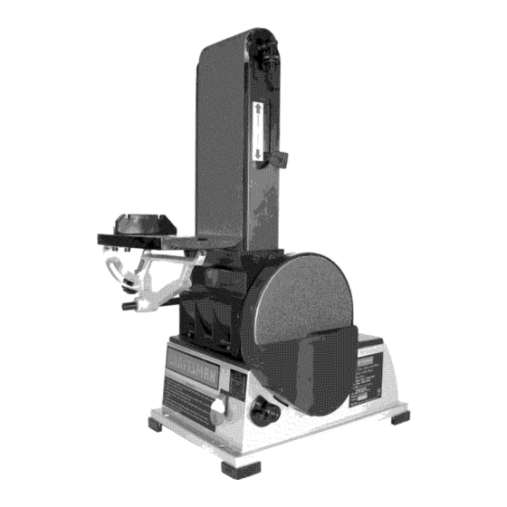
6 x 48" Belt, 9" Disc
SANDER
Model No.
351.225000
CAUTION:
Read and follow
all Safety Rules and Operating
Instructions
before First Use
of this Product. Keep this
manual with tool.
Sears, Roebuck and Co., Hoffman
Estates, IL 60179 U.S.A.
www.sears.com/craftsman
30664.00 Draft (04/14/09)
Advertisement
Table of Contents

Related Manuals for Craftsman 351.225000


Summary of Contents for Craftsman 351.225000
- Page 1 6 x 48" Belt, 9" Disc SANDER Model No. 351.225000 CAUTION: Read and follow all Safety Rules and Operating Instructions before First Use of this Product. Keep this manual with tool. Sears, Roebuck and Co., Hoffman Estates, IL 60179 U.S.A. www.sears.com/craftsman 30664.00 Draft (04/14/09)
- Page 2 TOOL • Extension cords should have a grounding prong and the three If this Craftsman tool fails due to a defect in material or work- wires of the extension cord should be of the correct gauge. manship within one year from the date of purchase, call 1- •...
- Page 3 MOUNT SANDER • Handle the workpiece correctly. Protect hands from possi- ble injury. Refer to Figure 2. • Turn machine off if it jams. Belt jams when it digs too NOTE: Although compact, the sander is heavy. At least two deeply into workpiece.
- Page 4 Refer to Figures 5 and 6, pages 4 and 5. POWER SOURCE WARNING: Do not connect sander to the power source until all assembly steps have been completed. Connect sander to a supply circuit protected by a circuit breaker or time-delay fuse. The motor is designed for operation on the voltage and fre- quency specified.
- Page 5 Receptacle Figure 6 - 2-Prong Receptacle with Adapter DESCRIPTION The Craftsman Belt and Disc Sanders are constructed • Do not use a 3-prong to 2-prong grounding adapter unless rugged die cast aluminum and cast iron providing stability and permitted by local and national codes and ordinances.
- Page 6 • Make sure abrasive belt always tracks properly. Correct • Quickly turn switch ON and OFF again. If belt moves to one tracking gives optimum performance. side, continue adjusting tracking nut as needed to center belt on drums. • After turning switch on, always allow belt and disc to come up to full speed before sanding or grinding.
- Page 7 Reposition table on support rod to ensure that gap between ° Finishing long pieces: Use belt in horizontal position with table and belt (disc) is 1/16" o r less. To reposition table, work stop. Apply only enough pressure to allow abrasive belt to remove material.
- Page 8 • If table needs adjustment, loosen the three bolts beneath • Replace cover and wing nuts. table, move table and secure in position. Figure 15 -Remove Wing Nuts and Cover Figure 13 - Table Adjustment REPLACING ABRASIVE DISC • Use a combination square to adjust miter gauge square to Refer to Figure 16.
- Page 9 LUBRICATION KEEP TOOL IN REPAIR The shielded ball bearings in this tool are permanently • If power cord is worn, cut, or damaged in any way, have it lubricated at the factory. They require no further lubrication. replaced immediately. • When operation seems stiff, a light coat of paste wax •...
- Page 10 Service Record Craftsman 6 x 9" Sander LDATE MAINTENANCE PERFORMED REPLACEMENT PARTS REQUIRED...
- Page 11 NOTES...
- Page 12 Models 351.225000 Figure 17 - Replacement Parts Illustration for Belt Housing 32 353t...
- Page 13 PART NO. DESCRIPTION QTY. 21425.00 Idler Assembly STD840610 6-1.0ram Hex Nut* STD8436 I0 6-1.0mm Fiber Hex Nut* 21426.00 Spring Platen 24628.00 STD833025 6-1.0 x 25mm Hex Head Bolt* 21428.00 Tension Lever Abrasive Belt 20768.00 STD870820 8-1.25 x 20mm Socket Head Bolt* STD840812 8-1.25mm Hex Nut*...
- Page 14 Models 351.225000 Figure 18 - Replacement Parts Illustration for Motor and Disc...
- Page 15 PART NO. DESCRIPTION QTY. 24645.00 V-Belt 21448.00 Miter Gauge Assembly 24653.00 Motor Pulley 07202.00 8-1.25 x 10mm Set Screw 30669.00 Retaining Ring 24652.00 Motor Assembly STD870512 5-0.8 x 12mm Socket Head Bolt 24651.00 30670.00 Plug 24666.00 Driven Pulley 30671.00 Disc Guard STD870535 5-0.8 x 35mm Socket Head Bolt* STD8451005...
- Page 16 PREPARE EL AREA DE TRABAJO PARA LA TAREA GARANTIA COMPLETA DE UN ANO PARA HERRAMIEN- REALIZAR TA CRAFTSMAN • Mantenga el Area de trabajo limpia. Las Areas de trabajo desordenadas atraen accidentes. Siesta herramienta Craftsman fallara por causa de defectos...
- Page 17 • Mantenga todas las partes listas para funcionar. Revise el La lijadora viene montada como una unidad. Es necesario protector u otras piezas para determinar si funcionan correcta- Iocalizar y tomar en cuenta las piezas adicionales que deben mente y hacen el trabajo que deben hacer.
- Page 18 Para utilizar la mesa con la correa: • La Figura 2 muestra las dimensiones de la base, los orificios de montaje y el espacio necesario para colocar el conjunto • Afloje el perno en la pieza de soporte de pivote (vea Ajuste la de la mesa y el conjunto de la correa en posici6n horizontal.
- Page 19 INSTRUCClONES PARA LA CONEXlON A TIERRA (Este tipo de adaptadores no se permiten en CanadA). Cuando est6 permitido utilizar este tipo de adaptadores, la lengQeta rigida ADVERTENClA: Si no se conecta correctamente el conductor de color verde o el terminal en el lado del adaptador deber_.n a tierra del equipo, se corre el riesgo de un electrochoque.
- Page 20 DESCRIPClON miento antes de comenzar a lijar o esmerilar. La Lijadora de correa y disco de Craftsman est,. construida • AsegQrese que el disco gire en el sentido de las manillas aluminio fundido...
- Page 21 AJUSTE DE ALINEACION DE LA CORREA • Se ha suministrado topes positivos ajustables para las posiciones horizontal y vertical. Consulte la Figura 8. AVISO" El tope horizontal se encuentra ubicado en la parte • Encienda y apague r_.pidamente la unidad para verificar alineaci6n.
- Page 22 Use la mesa para situar y sujetar la pieza que se est6 lijando. • Si es necesario ajustar la mesa, afloje los tres pernos Mantenga el extremo topado contra la mesa y mueva la pieza est_.n debajo de la mesa, mueva la mesa y fijela en su uniformemente a trav6s de la correa abrasiva.
- Page 23 • Hay correas abrasivas adicionales disponibles (v6ase Accesorios Recomendados en la p_.gina 15). • Empuje la palanca de tensidn hacia el tambor impulsor para ADVERTENCIA: AsegtJrese de que la unidad est6 desconecta- tensar la correa. da de la fuente de alimentacidn electrica antes de tratar de dar •...
- Page 24 SINTOMA MEDIDA CORRECTIVA CAUSA(S) POSIBLE(S) El motor no arranca 1. Voltaje bajo 1. Verifique el voltaje correcto de la linea de alimentaci6n 2. Circuito abierto en el motor o 2. Inspeccione todas las conexiones de conductores conexiones sueltas en el motor para ver que no haya conexiones sueltas o abiertas 3.
- Page 25 NOTAS...
- Page 26 NOTAS...
- Page 27 NOTAS...
- Page 28 Your Home For expert troubleshooting and home solutions advice: aHa e www.managemyhome.com For repair - in your home - of all major brand appliances, lawn and garden equipment, or heating and cooling systems, no matter who made it, no matter who sold it! For the replacement parts, accessories owner's manuals that you need to do-it-yourself.