Table of Contents
Advertisement
Available languages
Available languages
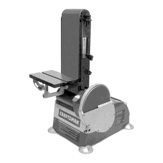
Operator's Manual
6 x 48" Belt, 9" Disc
SANDER WITH DUST COLLECTION
Model Nos.
351.225930
CAUTION:
Read and follow
all Safety Rules and Operating
Instructions
before First Use
of this Product. Keep this
manual with tool.
Sears, Roebuck and Co., Hoffman Estates, IL 60179 U.S.A.
www.sears.com/craftsman
23634.02 Draft (07/14/05)
Advertisement
Table of Contents

Related Manuals for Craftsman 351.225930


Summary of Contents for Craftsman 351.225930
- Page 1 SANDER WITH DUST COLLECTION Model Nos. 351.225930 CAUTION: Read and follow all Safety Rules and Operating Instructions before First Use of this Product. Keep this manual with tool. Sears, Roebuck and Co., Hoffman Estates, IL 60179 U.S.A. www.sears.com/craftsman 23634.02 Draft (07/14/05)
- Page 2 ONE-YEAR FULL WARRANTY CRAFTSMAN TOOL • Keep all parts in working order. Check to determine that the If this Craftsman tool fails due to a defect in material guard or other parts will operate properly and perform their intended function.
- Page 3 ° Sander can be installed on a workbench or a tool stand (see Recommended Accessories, page 15) using bolts, lock washers and hex nuts (not supplied). Refer to Figure ° Figure 2 shows the base dimensions, mounting holes and Check for shipping damage.
- Page 4 Tousethetable withthebelt: • Remove work stop from belt a ssembly. • Loosen b oltinpivot b racket. Move belt a ssembly tothe vertical position, and secure i nposition b ytightening bolt. • Insert t able support rodintothebelt a ssembly bracket. Secure u sing bolt ( A), m aking s ure bolt t ightens ontothe flatsurface o ftherod.
- Page 5 DESCRIPTION not properly grounded. To ensure proper ground, grounding The Craftsman Belt and Disc Sanders are constructed means must be tested by a qualified electrician. rugged die cast aluminum and cast iron providing...
- Page 6 SPECIFICATIONS Some examples of these chemicals are: • Lead from lead-based paints. MODEL 225930 • Crystalline silica from bricks and cement and other Belt size ........6 x 48" masonry products. Belt platen area ......7 x 17" • Arsenic and chromium from chemically-treated lumber.
- Page 7 ADJUSTING TABLE ANGLE Refer to Figure * To adjust table angle, loosen knob, tilt table to desired position, then secure by tightening knob. ,, Reposition table on support rod to ensure that gap between table and belt (disc) is _/_6"or less. To reposition table, loosen bolt, move table on rod and secure...
- Page 8 • Finishing long pieces: Usebelt i nhorizontal position with • If table needs adjustment, loosen the three bolts beneath work stop. Apply o nly enough pressure to allow abrasive table, move table and secure in position. belt to remove material. Use work stop to position and secure work...
- Page 9 * Slide new belt over the drive and idler drums; center belt on drums. * Additional abrasive belts are available (See Recommended WARNING: Make certain that the unit is disconnected from Accessories, page 15). power source before attempting to service or remove * Push tension lever towards...
- Page 10 SYMPTOM CORRECTIVE ACTION POSSIBLE CAUSE(S) Motor will not start 1. Low voltage 1. Check power line for proper voltage 2. Open circuit in motor or loose 2. inspect all lead connections on motor for loose or connections open connection 3. Defective switch 3.
- Page 11 Service Record Craftsman Sander with Dust Collection DATE MAINTENANCE PERFORMED REPLACEMENT PARTS REQUIRED...
- Page 12 Model351.225930 Figure 19 - Replacement Parts Illustration for Belt and Disc 19 20 10 15...
- Page 13 PART NO, DESCRIPTION QTY. PART NO. DESCRIPTION QTY, 21425.00 21443.00 Switch Box Idler A ssembly 23902,00 Dust C over STD833020 6-1,0 x20mm HexHead Bolt* 21428,00 Tension Lever STD863610 6-1.0 x 10mm PanHead Screw'* 21441.00 20768.00 Abrasive Belt Upper Cover STD315545 21426,00 Spring 6004ZZ B all B earing*...
- Page 14 Models 351.225930 Figure 20 - Replacement Parts Illustration for Motor and Dust Collection "" ../ 20 [ 29...
- Page 15 PART NO. QTY. DESCRIPTION Upper Body 21464.00 Bottom Plate 21455.00 Hose 01043.00 6-1.0 x 8ram Set Screw 21452.00 Motor 21453.00 Motor Assembly (Includes Key Nos. 4, 5, 7, 8 and 9) 21472.00 Centrifugal Switch 21471.00 Stationary Switch 21470.00 Capacitor 300MFD, 125VAC 22121.00 Bag Clamp...
- Page 16 Ilaves del arrancador para impedir GARANTIA COMPLETA DE UN AgO PARA HERRAMIENTA cualquier uso involuntario de las herramientas mecanicas. CRAFTSMAN SE DEBE DAR MANTENIMIENTO A LA HERRAMIENTA Siesta herramienta Craftsman fallara por causa de defectos en el material o en la mano de obra en un lapso de un argo a partir de •...
- Page 17 ,, Evite que la herramienta se encienda accidentalmente. AsegQrese que el interruptor de la herramienta esta en la posici6n OFF (apagado) antes de enchufarla. ,, No fuerce la herramienta. Funcionara en la forma mas eft- Consulte las Figuras 2-5. ciente a la velocidad para la cual se dise56.
- Page 18 INSTALAClON CON JUNTO DE LA MESA Consulte las Figuras 3 y 4. El conjunto de mesa incluido se utiliza con ambos, el disco y la correa. Para utilizar la mesa con el disco: ,, Inserte la varilla de soporte de la mesa en la base de la lijadora.
- Page 19 las Normas para Instalaciones Electricas (National Electric Code) y los c6digos y regulaciones locales. ADVERTENClA: Esta tarea debera ser realizada por un Consulte las Figuras 6, 7 y 8 en las paginas 19 y 20. electricista calificado. Se puede usar temporalmente un adaptador de 3 puntas a 2 FUENTE...
- Page 20 DESCRIPClON miento antes de comenzar a lijar o esmerilar. La Lijadora de correa y disco de Craftsman est& construida ,, AsegOrese que el disco gire en el sentido de las manillas aluminio fundido...
- Page 21 una mascara para la cara o respirador adecuadamente ajusta- dos, aprobados por MSHA/NIOSH INTERRUPTOR DE ON/OFF (ENCENDIDO/APAGADO) Consulte la Figura 9. El interruptor de encendido y apagado se encuentra en la parte delantera superior derecha del gabinete. Para encender la Iijado- ra, cambie la posici6n del interruptor a la posici6n...
- Page 22 AJUSTE ANGULO DE LA MESA USO DE LA CORREA ABRASlVA PARA TRABAJOS DE ACABADO Consulte la Figura 12. • Acabado de las superficies planas: Sujete firmemente la pieza • Para ajustar el angulo de la mesa, afloje la manilla, incline de trabajo con las dos manos;...
- Page 23 ,, Despues de cuadrar la mesa y la guia de ingletes con la correa (o el disco), cambie la posici6n del indicador de angulo en la escala de la guia de ingletes para ajustar la guia al angulo deseado y fijela en esa posicion con la manilla.
- Page 24 CAMBIO DEL DISCO ABRASlVO Consulte la Figura 18. Desmonte el conjunto de la mesa. ADVERTENCIA: Asegt_rese de que la unidad este desconecta- ,, Retire la cubierta del disco. Para esto, afloje y extraiga seis da de la fuente de alimentaci6n electrica antes de tratar de dar tornillos.
- Page 25 MEDIDA CORRECTIVA SINTOMA CAUSA(S) POSIBLE(S) El motor no arranca 1. Voltaje bajo 1. Verifique el voltaje correcto de la linea de alimentaci6n 2. Circuito abierto en el motor o 2. Inspeccione todas las conexiones de conductores conexiones sueltas en el motor para ver que no haya conexiones sueltas o abiertas...
- Page 26 NOTAS...
- Page 27 NOTAS...
- Page 28 ® Registered Trademark Trademark Service Mark of Sears, Roebuck and Co. ® Marca Registrada / TM Marca de F_brica / s_ Marea de Servicio de Sears, Roebuck and Co. MC Marque de commerce Marque d_pos_e de Sears, Roebuck and Co. ©...