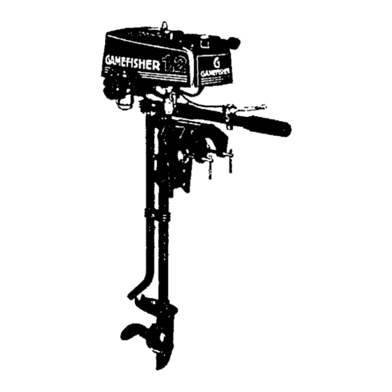
Summary of Contents for Sears Gamefisher 298.585130
- Page 1 MODELNO. 298.585130 • owner's responsibility • maintenance ,_ operation • trouble shooting ,= replacement paris Publication 970-35118-203...
-
Page 2: Specification
TABLE OF CONTENTS Pag,,No. SPECIFICATIONS ......... OWNER'S RESPONSIBILITY ......... STEERING HANDLE INSTALLATION MAINTENANCE , ......... LUBRIC'_kTION GEAR HOUSING ....,.... MUFFLER INSPECTION ........PROLONGED STORAGE ........'OPERATIONS ..........BOAT MOUNTING ........STEERING ADJUSTMENT ........ 2-CYCLE ENGINE FUEL MIXTURE ...... -
Page 3: Safety Checklist
IMPORTANT Owner's Responsibility and Operating Safety Check List BE SURE TO READ DO THE. FOLLOWING BEFORE OPERATING YOUR OUTBOARD MOTOR SAFETY CHECK LIST Learn observe the boating Jaws of the U.S, Coast, Guard, state, local author- ities. U,S. Coast Guard regulations require the following:... -
Page 4: Major Parts
MAJOR PARTS -Fuel Filler Cap PowerHeed and Air Venl Screw Spark Plug Slarter Handle Throllle Conlrol Lever Fuel Shul-oflVatve Sleeting Handle Fuel Sediment B ow[ and Filter Idenlilicalion P lale Tilt Pin Adjustment Transom Bracket ClampSludHandles Muffler Pipe ExheuslOullel Drive Shall Pipe CoUerPin CavilaUon Plate Fill and Drain Plug... - Page 5 INTENANCE ! FEATURE INFORMATION This outboard motor special design When lubricant has completely drained, features as shown in Figure 1; reptape parts refill gear housing Your selection our Marine Products will using filling procedure above, !provide with many hours of enjoyable best results, lubricate...
- Page 6 JPI'HA[ IL1N BOAT MOUNTING Mount the motor on the center of the boat transom (stern). (See Ftgure4). CAUTION Hand t_ghten clamp bracket clamp stud handles stmultaneously. use a wrench other device that would cause damage to brackets. Occasionally check to be sure lamp stud...
-
Page 7: Operation
OPERATION 2-CYCLE ENGINE FUEL MIXTURE Use a good grade of regular gasoline. (See mix- VENT• ing table below,) CAUTION Always usa BIA certified TC-W oil in the 50:1 ratio, Failure to do =0 may result excessive spark plug fouling, piston scoring, or bearing failure. - Page 8 OPERATION FLOODING To cfear engine of excess fuel, move choke lever '*Off" position throttle lever half throttle position. Pull recoil starter handle until engine starts and continues to run. .÷ CARBURETOR ADJUSTMENTS Your motor has e fixed high speed iet. Idle Adiustment been...
- Page 9 OPERATION FLYWHEEL MAGNETO IGNITION CONTACT POINT$_ SYSTEM CONTACT-BREAKER The magneto ignition system consists of the TIMING LOCKING SCREWS_ following component parts: Contact Points, CONTACT-BREAKER _%_,_"'_"-_ Condenser, Ignition Coil. (See Figure 13). BASE PLATE Inspect the following if engine fails or is Figure 13 hard to start: Spark...
-
Page 10: Troubleshooting Checklist
TROUBLESHOOTING CHECK LIST "Take your outboard motor Into any one of o'_e_ 2000 Sear=Servi¢e Units..× × • Fuel Tank Empty rue| Shut-Oil Valve Closed Fuel"Line Kinked or Pinched _'/, Fuel Filter Dirty or Clogged _. ; Vent ,.¢crewon Fuel Tank Filter Cap Closed •... -
Page 11: Replacement Parts
REPLACEMENT PARTS MODEL Noo298.585130... - Page 12 FIG. I ENGINE ..-J "- 8980...
- Page 13 FIG. I ENGINE REF. No. PART No, PART NAME Q'ty 157-04000.900 SPARK PLUG CAP ASS'Y 018-00562-200 SPARK PLUG RCJ-8 002.00500-804 CYLINDER COMP CYLINDER GASKET 017-00501-202 PISTON RING 041.00000.200 039,0000o-201 PISTON PIN CfRCRIP 031-03 500-200 PI STON 1-10 037-00000-200 PISTON 1.11 046-00501-803 CRANKSHAFT COMP...
- Page 14 FIG.2 ENGINE COVER & MUFFLER 3534 4530...
- Page 15 F|G.2 ENGINE COVER & MUFFLER _EF. PART PART NAME Q'ty 756-00537-90O RECOIL STARTER ASS'Y 585-35100.902 TANK CAP ASS*Y 300.35108-200 ENGINE COVER 2, 4 600-35100-203 TANK SUPPORT RING 401-36100-203 TANK 790.00601-202 STARTER PAWL SPRING 992-01050-0 WASHER 788-00601-203 STARTER PAWL 822-00601-200 STARTER PAWL SHIM 2.10 793-10200.200...
- Page 16 FIG.3 RECOIL STARTER PART NAME REF. PART No. Q'ty 3-0-1 756-00537-900 RECOIL STARTER ASS'Y 772-00537-200 ° RECOIL STARTER BODY 774-04015-204 * STARTER PULLEY 779-01006-201 * RECOIL SPRING 776-01006-207 • PULLEY SHAFT • ROPE 783-OO517-200 3-11 780-O0601-201 • HANDLE GUIDE 3-12 785-102_7-901 •...
- Page 17 FtG.4 CARBURETOR REF. No, PART NAME PART No, Q'ty " "o 4-0.1 455.22620.900 CARBURETOR ASS°Y 560-22602.200 • RUBBER 597-22603-200 • THROTTLE CABLE ADJUSTER • BODY 595-22602-2OO • THROTTLE VALVE SPRING 594-22602-200 619-22602-200 • THROTTLE SPRING SEAT " JET NEEDLE ASS'Y 592-22602-910 •...
- Page 18 FIG.5 HANDLE & BRACKET 17.,...
- Page 19 FIG.5 HANDLE & BRACKET REF. No. PART PARTS NAME Q'ty 885-00568-800 THROTTLE WIRE COMP 5-'I 870-00569-900 THROTTLE LEVER ASS'Y 145-35118-200 JOINT PiPE HOLDER 990-11060-182 SCR EW 6 x 1B 992-10060-042 S. WASH_'R 6 990-21060-302 BOLT 6 x 30 992-10060-042 S. WASHER 5.
-
Page 20: Drive Shaft
DRIVE SHAFT PiPE & GEAR CASE 7-----Q -8-3 "8-2... - Page 21 FIG.6 DRIVE SHAFT PiPE & GEAR CASE REF. No. PART NAME PART Q't'y JOINT PIPE 090-35118.200 075.35100-205 DRIVE SHAFT 076-35100.203 DRIVE o86.35 lOO-20o BEARING HOLDER CRIP 081-35100-200 DRIVE SHAFT BEARING d,39-35100.203 BEARING HOLDER JOINT PIPE PACKING 091-35100-202 030-35100.900 GEAR CASE ASS'Y 6- 8-1 999.61629-000 "...
- Page 22 SERVICE MEMO...
-
Page 23: How To Order Repair Parts
For quick service or repair, take your Outboard Motor to an,,, Sears Service Unit throughout FULL ONE YEARWARRANTYON U.S. and Canada. Each Service Unit is staffed OUTBOARD MOTOR trained t.echnicians, using Sears approved For oneyear Irom thefirst day 0I use of parts repair procedures...


