Table of Contents
Advertisement
Advertisement
Table of Contents

Related Manuals for X10 AIRSIGHT XX34A


Summary of Contents for X10 AIRSIGHT XX34A
- Page 1 Indoor Wireless/Wired IP Network Camera Model XX34A User Manual...
-
Page 2: Table Of Contents
CONTENTS 1.1 F ......................................3 EATURES 1.2 P ....................................... 3 ACKING 1.3 P ....................................4 RODUCT IEWS 1.4 PC S ................................. 6 YSTEM EQUIREMENTS ... -
Page 3: Features
1 INTRODUCTION This is an integrated wireless IP Camera solution. It combines a high quality digital Video Camera with network connectivity and a powerful web server to bring clear pictures to your Desktop from anywhere on your local network or over the Internet. -
Page 4: Product Views
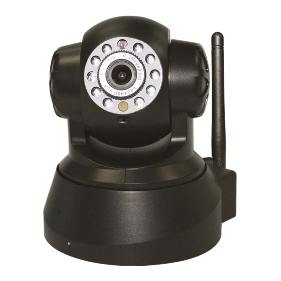
1.3 Product Views 1.3.1 Front View Figure 1.1 1 Light Sensitive Hole: For light sensitive photocell 2 Infrared LED: 10 LEDs 3 LENS: CMOS sensor with fixed focus lens. (Default is 6mm, 3.6mm optional) 4 Network Indicator LED: If there is network activity, the LED will blink 5 Microphone: Build-in microphone 6 Speaker: Build-in speaker... -
Page 5: Rear Panel
1.3.2 Rear Panel Figure 1.2 LAN: RJ-45/10-100 base T Power: DC 5V/2A power supply Network Light: The green LED is on when connected to the network, the yellow LED blinks when data is transferred. -
Page 6: Pc System Requirements
1.4 PC System Requirements System configuration requirements: CPU: 2.06 GHZ or above. Memory: 256M or above. Network Card: 10M or above. Display Card: 64M or above memory. Recommended Operating system: Windows XP, Windows Vista, Windows 7. 1.5 Hardware Installation Follow the steps below to set up your camera hardware. - Page 7 2. ActiveX: Double click “Appinstall.exe”—“Next”—“Install”—“Finish”. Figure 1.5 Figure 1.6 Figure 1.7 ...
- Page 8 Figure 1.8 After this is done, the icon “IP Camera Tool” will be displayed on your desktop . CAUTION: Before installing and using the product, please read the following precautions carefully and make sure they are fully understood.
-
Page 9: Software Operation
2. SOFTWARE OPERATION 2.1 IP Camera Tool When the Device has been mounted properly, you can double-click the Icon “IP Camera Tool” and a dialog box shown in Figure 1.9 will pop up . Figure 1.9 Note: The software searches IP Servers automatically over your LAN. -
Page 10: Basic Properties
Figure 2.0 2.1.1 .1 Basic Properties There is some device information in the Basic Properties, such as Device ID, System Firmware Version, and Web UI Version.(Figure 2.1). The Device ID is the camera’s MAC ID, which should be the same as shown on the sticker on the bottom of the camera. - Page 11 Figure 2.2 Obtain IP from DHCP server: If clicked, the device will obtain IP from DHCP server. In other words, the camera will have a dynamic IP. (Make sure the Router which the camera connects to has DHCP function and DHCP is enabled).
-
Page 12: Upgrade Firmware
2.1.1.3 Upgrade Firmware Enter the correct User and Password to upgrade system Firmware and Web UI. Please upgrade system firmware first and then upgrade Web UI or it may damage the camera.(Figure 2.4). Figure 2.4 Please download the firmware package for the correct type of your camera before you upgrade. - Page 13 2. To access the camera by IE Browser directly, just type the camera’s IP address, for example, if the camera’s IP address is 192.168.1.123: Figure 2.5 Figure 2.6 The default user name is admin, no password (leave blank).
-
Page 14: For Ie Browser
2.3 For IE Browser Choose ActiveX Mode (For IE Browser), and sign in Figure 2.8 Figure 2.9 The first time you login to the camera, you might get an ActiveX prompt as in the picture above, please click the prompt and choose Run Add-on, refresh and login to the camera again, then will see live video, as below. - Page 15 Note: If there is still no live video after you run ActiveX, and a red cross shows in the center of the screen, or even just a black screen, please try to enable the ActiveX options of IE security settings. Please do the following steps: 1.
-
Page 16: For Safari, Firefox, Google Browser
Figure 3.2 NOTE: Make sure that your firewall or anti-virus software doesn’t block the software or ActiveX. If you couldn’t see live video, please close your firewall or anti-virus software, and try again . 2.4 For Safari, Firefox, Google Browser Choose Server Push Mode (For Safari, Firefox, Google Browser), and sign in. -
Page 17: For Mobile Phone
2.5 For Mobile Phone Choose Sign in mobile phone, and sign in. Mobile phone doesn’t support ActiveX, so only some basic functions are available in this mode. It supports iPhone, Smart phone, 3G phone, etc. Normally, if the mobile phone supports network video, then it should work with your IP Camera. - Page 18 Figure 3.5 Channels: The IE software supports 9 channels. Click to get different windows. Click this one to view the main channel of the camera you login to. Click this one to view 4 Channels of cameras that are connected, from CH1 to CH4.
-
Page 19: Osd Settings
OSD Settings: Figure 3.6 OSD: Means “On-Screen Display”, click “Audio video” > “OSD”, set display date and time on the video. Disabled: Clicking this one means clear the OSD. Color: Can set the OSD text color as black, yellow, red, white, blue etc. -
Page 20: Top Menu
Figure 3.8 Figure 3.9 TOP Menu Figure 4.0 Click to get live video. When you want to get back to live video from other menus, just click it. Only under live video, you can do the operation on the right side, such as play, stop, snapshot etc. -
Page 21: For Operator
2.8 For Operator When you login as Operator, you can enter the IP Camera for Operator. For operator, it not only supports all the functions for Visitor, but also supports these functions below: Figure 4.1 Audio Video Settings ... - Page 22 Mode, Bright, Contrast Settings Figure 4.3 Mode: This mode is optional, 50HZ/60HZ for the users who use 50HZ/60HZ frequency, outdoor for users who want to use the camera to monitor towards an outdoor environment. NOTE: The camera should be used in an indoor environment (unless protected from the elements).
-
Page 23: For Administrator
Preset Settings Figure 4.5 Set Preset Position. It supports 15 preset positions. To control the camera’s rotation to a preset position, click Set Preset Position button it will pop-up a dialog frame (Figure 4.5), choose the number (1-15) you want to set it to. -
Page 24: Settings As Administrator
3 SETTINGS AS ADMINISTRATOR Administrator supports all the settings and operations of the camera. There are some special functions only for administrator as below: Figure 4.6 3.1 Multi-Device Settings ... - Page 25 Figure 4.7 Click Live Video and then select to see four channels, or click to see nine channels. Figure 4.8 ...
- Page 26 Figure 4.9 3.1.2 Set Multi-Device for WAN If you want to view cameras from the internet, you have to add these devices by DDNS domain name. Make sure all these cameras you want to add have DDNS set successfully. (See 3.7 DDNS Service Settings) Login to the first camera by DDNS domain name and port, this camera will be as the host camera.
- Page 27 name, and without “http://”, it’s not the LAN IP address. If you have several cameras, you can use the same DDNS domain name, just set different port number for each different camera. Figure 5.1 Note: Add the other camera in the same way, Click submit to add all of them.
-
Page 28: Upgrade Device Firmware
Click Live Video and then selec t to see four channels, or to see nine channels. In this case, you can see all the cameras from a remote position by internet, for example, if you are on a business trip, you can use the first camera’s (Host camera) DDNS to view all the devices via the internet. -
Page 29: Restore Factory Settings
3.1.4 Restore Factory Settings Click Restore Factory Settings, will pop-up a prompt, select OK, all the parameter will be returned to factory settings, and the device will reboot. Figure 5.5 3.1.5 Reboot Device Click Reboot the device, will pop-up a prompt, select OK, then the device will reboot... - Page 30 Figure 5.7 If you don’t know the Subnet Mask, Gateway, DNS Server. Please check the Local Area Connection Status of your computer; it contains all this information, steps as below: 1.
-
Page 31: Wireless Lan Settings
If you don’t know the DNS Server, you can set it the same as Gateway. If the router supports DHCP function, you can choose “Obtain IP from DHCP Server” to get dynamic IP. Figure 6.0 Http Port: In most cases, you can leave this value as-is. - Page 32 Figure 6.2 Figure 6.3 Figure 6.4 ...
-
Page 33: Adsl Settings
Figure 6.5 3.5 ADSL Settings When connected to the Internet through ADSL directly, you can enter the ADSL username And password obtained from ISP. Figure 6.6 Figure 6.7 3.6 UPnP Settings Click UPnP Settings to choose Using UPnP to Map Port: ... -
Page 34: Ddns Service Settings
Figure 6.9 NOTE: Here UPnP is only for port forwarding. It relates to the security settings of your router, make sure the UPnP function of your router is ON. Attention: If your router doesn’t support UPnP function, it may show error information. - Page 35 Third Party DDNS If you use third party DDNS, please choose the server you use, such as “3322.org” or “dyndns.org” as below: Figure 7.2 Figure 7.3 You have to register an account first, enter the user, password, and host. NOTE: Only one DDNS can be chosen, for example, if you use the manufacturer’s DDNS, the third party one won’t work, if you use the third party DDNS, the manufacturer’s one won’t work.
- Page 36 Figure 7.4 Make sure the “Subnet Mask”, “Gateway”, “DNS Server” is the same as your router. Set Port Forwarding in the router. This is the most important step. You need to set port forwarding in your router, to refer to the IP of your camera correctly, for DDNS to work.
- Page 37 BELKIN: 1. Login to the router. 2. Choose “Firewall”, select “Virtual Servers” 3. Input the port (don’t use 80) and IP address, then click save. NOTE: The port and IP address should be the same as the camera. Figure 7.6 DLINK: 1.
-
Page 38: System Settings
After all these 4 steps are done, you can use DDNS, check the DDNS status from the camera as below, and get the link of DDNS for internet viewing. Step: “Login”>”System”>”Device Info”... -
Page 39: Device Info
3.8.1 Device Info You can find the information about Device ID, Firmware Version, Embedded Web UI Version, Alias, Alarm Status, DDNS Status, UPnP Status and MSN status. Figure 8.1 3.9 Alias Settings Default device name is anonymous. -
Page 40: Users Settings
Figure 8.4 3.11 Users Settings Eight accounts are acceptable for this system. Here you can set the user names and password as Administrator, Operator or Visitor, with permission for them as below: ... -
Page 41: Pan, Tilt, (Ptz) Settings (Note, There Is No Zoom Feature On This Model)
3.12 Pan, Tilt, (PTZ) Settings (note, there is no Zoom feature on this model) Figure 8.6 1. Go center on boot: The camera rotates to the center automatically when it starts. 2. - Page 42 1) Backup: Backup all the IP Camera Parameters, if you want to save all the current settings that you have set already, you can click Submit, then all the parameters you set will be stored as a parameters bin file. 2)Restore: Restore all the IP Camera Parameters, if you want to change the camera’s settings to a certain status which has a backup, click Browse to load the bin file, then Submit it.
-
Page 43: Other Settings
After you run your MSN, open the chat dialog, type in the word “url?”, after a few seconds, you will get a reply for the remote access IP address for this IP camera. 3.15 Other Settings ... - Page 44 Sender: Make sure the sender mailbox server provider supports SMTP, and the mailbox should not enable SSL or TSL encryption. Receiver: Here you can set four receivers. For receiver, there is no SMTP limitation. SMTP Server: The sender’s SMTP Server.
-
Page 45: Ftp Service Settings
3.17 FTP Service Settings Set the FTP Service, you can upload images to your FTP server when motion is detected . Figure 9.3 Figure 9.4 FTP Server: If your FTP server is set up in LAN. You can set as Figure 9.3. If you have an FTP server that can be accessed from the Internet, you can set as Figure 9.4. -
Page 46: Alarm Service Settings
Figure 9.5 If it prompts error information as follows. 1) Cannot connect to the server. Please check FTP Server is correct. 2) Network Error. Please try later. 3) Server Error. 4) Incorrect user or password. -
Page 47: Motion Detect Sensitivity
Figure 9.7 After you enable motion detect armed, if there is motion detected, the Alarm Status will turn to Motion Detect Alarm. (Figure 9.8). Figure 9.8 3.18.2 Motion Detect Sensitivity You can choose level 1-10;... - Page 48 3.18.3 Alarm Input Armed / IO Linkage on Alarm If you want to connect external alarm devices, when it’s an alarm input device, choose Alarm Input Armed to enable it, when it’s an output device, choose IO Linkage on Alarm to enable it.
-
Page 49: Send E-Mail On Alarm
3.18.4 IO Pins for IO Alarm Linkage Figure 10.3 I/O PINS: 1 Output 2 Output 3 Alarm input 4 Input (GND) Input pins: The input pins can be used for 1-way external sensor input. For example, you may connect a Passive Infrared (PIR) Sensor to it for motion detection. - Page 50 Figure 10.5 Sound on Alarm When motion is detected, there will be a beep sound during the alarm, you can control this sound here. If Enabled, there will be sound once alarmed. If Canceled, there will be no sound once alarmed.
-
Page 51: Path Settings
3.20 Path Settings Figure 10.8 Here you can set record path and alarm record path for the camera Figure 10.9 Record Path: Here you can set the manually record path. Click then start manual recording, the record file will be saved to the specified path you set here. -
Page 52: Server Push Mode (For Safari, Firefox, Google Browser)
3.21 Server Push Mode (For Safari, FireFox, Google Browser) Choose Server Push Mode, login the camera, you will see the main user interface as below: Figure 11.2 NOTE: Server Push Mode does not support ActiveX. Play, Stop, Record, Audio, Talk, Multi-device settings, Path settings functions are controlled by ActiveX, so if you use Safari, Firefox, Google chrome browser, it is not possible to use these options. -
Page 53: Sign In Mobile Phone
3.22 Sign in mobile phone If you are using a mobile phone, choose Sign in mobile phone, login to the camera, you will see the main user interface as below: Figure 11.3 NOTE: Mobile phone Mode doesn’t support ActiveX. -
Page 54: Appendix
4. APPENDIX 4.1 Frequently Asked Questions Note: For most problems you might encounter, please check Network connections first. Check the working status revealed by the indicators on the network server, hub, exchange and network card. If abnormal, check the network connections. - Page 55 4.1.6 UPnP always fails UPnP only contains port forwarding in our recent software. Sometimes, it might fail to do port forwarding automatically because of firewall or anti-virus software. It also relates to your router’s security settings. So we recommend you do port forwarding manually.
-
Page 56: Problems With Network Bandwidth
4.1.13 There’s no picture (Problems with ActiveX Controller) If using IE browser to connect the camera for the first time, and there is no image displayed, you might need to install ActiveX. -
Page 57: Specifications
5. SPECIFICATIONS Model XX34A Image Sensor Sensor 1/4” Color CMOS Sensor Resolution 640 x 480 Pixels (300k Pixels) IR Lens f: 6mm, F 2.0 (3.6mm lens optional) Viewing Angle 60 Degree (3.6mm lens is 90Degree) Minimum Illumination... -
Page 58: Obtaining Technical Support
X10 Wireless Technology, Inc. Limited One Year Warranty X10.com, a division of X10 Wireless Technology, Inc. (X10) warrants X10 products to be free from defective material and workmanship for a period of one (1) year from the original date of purchase at retail. X10 agrees to repair or replace, at its sole discretion, a defective X10 product if returned to X10 within the warranty period and with proof of purchase.