
Related Manuals for Sony FCB-H11


Summary of Contents for Sony FCB-H11
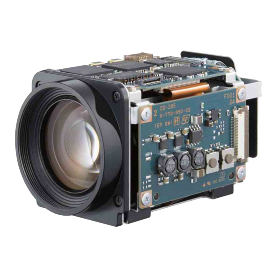
- Page 1 A-D3N-100-11(1) HD Color Camera Module Technical Manual FCB-H11 2008 Sony Corporation...
-
Page 2: Table Of Contents
Table of Contents Features ..............3 Precautions ..............4 Locations of Controls ..........5 Basic Functions ............6 Overview of Functions ..........6 Eclipse ..............12 Vibration Specifications ..........12 Initial Settings and Position Preset ......13 Mode Condition ............14 Command List ............ -
Page 3: Features
Overview Features • The CMOS video camera provides 2,000,000 effective picture elements (pixels) that can shoot high-definition images to offer superior picture quality. • The camera is compatible with 8 formats, including the Full HD (1080i high definition) video format, which is equivalent to an HD-TV broadcast. -
Page 4: Precautions
Otherwise, you may get an electric software may damage hardware, the application shock or a fire may occur. program, or the camera. Sony Corporation is not liable for any damage that may occur under these conditions. In case of abnormal operation, contact your authorized... -
Page 5: Locations Of Controls
Locations of Controls Locations of Controls Front Right side Bottom 1 Lens 4 CN901 jack 2 WIDE button 5 Tripod screw hole 3 TELE button When a tripod is used, please use 5 mm ( inches) or less screw to attach it to the camera. -
Page 6: Basic Functions
Basic Functions Basic Functions Zoom Overview of Functions The camera employs an 10× optical zoom lens combined with a digital zoom function allowing you to VISCA commands are the basis of camera control. zoom up to 120×. In general Lens specifications: Optical 10×, f = 5.1 to 51 mm (F1.8 to F2.1) •... -
Page 7: White Balance
Basic Functions Focus • Near Limit Mode Can be set in a range from about 4.5 m (2000) to 1 cm Focus has the following modes, all of which can be set (C000). using VISCA Commands. The focus range is narrowed by excluding the •... - Page 8 Basic Functions AE – Shutter Priority Automatic Exposure Mode The shutter speed can be set freely by the user to a The variety of AE functions, which allow video signal total of 21 steps – 15 high speeds and 6 low speeds. to output the optimum image for subjects from low When the slow shutter is set, the speed can be light conditions to bright light conditions, are...
- Page 9 Basic Functions AE – Iris Priority Parameter IRIS (F1.8) GAIN The iris can be set freely by the user to 18 steps F No. between F1.8 and Close. F1.8 18dB The gain and shutter speed are set automatically F1.8 15dB according to the brightness of the subject.
-
Page 10: Exposure Compensation
Basic Functions rest should be set to 20%. The range of the Spot AE Back Light Compensation frame is fixed to 5 blocks vertically and 4 blocks horizontally. When the background of the subject is too bright, or when the subject is too dark due to shooting in the AE mode, back light compensation will make the subject appear clearer. - Page 11 Basic Functions The settings are recalled when the power is turned on. Gamma For setting items, see the “Initial Settings and Position Selects the desired gamma curve of the camera. Preset” section on page 13. • Normal Reproduces images with the standard video gamma Custom Preset curve.
-
Page 12: Eclipse
Basic Functions Eclipse When designing the housing, refer to the dimensional allowance as shown in the figure below. Vibration Specifications Test Method (Random vibration) • Fix the camera at the four fixation points of the base using M2 screws. • Perform the random vibration test under the following conditions in the X, Y and Z directions for 20 minutes in each direction. -
Page 13: Initial Settings And Position Preset
Basic Functions Initial Settings and Position Preset The initial values are those set at the factory. Settings for items that will be retained even when the power to the camera is turned off are indicated by a “a,” those that will be lost are indicated by an “×.” Custom Memroy position Mode/Position... -
Page 14: Mode Condition
Basic Functions... - Page 15 Basic Functions...
- Page 16 Basic Functions...
- Page 17 Basic Functions...
-
Page 18: Command List
• Start bit : 1 • Stop bit : 1 • Non parity Flow control using XON/XOFF and RTS/CTS, etc., is not supported..............................................1) VISCA is a protocol which controls consumer camcorders developed by Sony. “VISCA” is a trademark of Sony Corporation. -
Page 19: Visca Communication Specifications
Command List VISCA Communication Specifications list, as the header is 8X, input the address of the VISCA packet structure FCB-H11 at X. The header of the reply packet from The basic unit of VISCA communication is called a the FCB-H11 assigned address 1 is 90H. The packet packet (Fig.1). - Page 20 Command List Command and inquiry Socket number ● Command When command messages are sent to the FCB-H11, it Sends operational commands to the FCB-H11. is normal to send the next command message after ● Inquiry waiting for the completion message or error message Used for inquiring about the current state of the to return.
-
Page 21: Visca Device Setting Command
Inquiry Inquiry Packet Reply Packet Description CAM_VersionInq 8X 09 00 02 FF Y0 50 GG GG HH HH JJ JJ KK FF GGGG: Vender ID (0020: Sony) HHHH = Model ID 044B: FCB-H11 JJJJ = ROM revision KK = Maximum socket # (02) - Page 22 Command List VISCA Command/ACK Protocol Command Command Message Reply Message Comments General Command 81 01 04 38 02 FF 90 41 FF (ACK)+90 51 FF Returns ACK when a command has been accepted, and (Example) (Completion) Completion when a command has been executed. 90 42 FF 90 52 FF 81 01 04 38 FF...
-
Page 23: Error Messages
Command List VISCA Camera-Issued Messages ACK/Completion Messages Comments Command Messages z0 4y FF Returned when the command is accepted. (y:Socket No.) Completion z0 5y FF Returned when the command has been executed. (y:Socket No.) z = Device address + 8 Error Messages Comments Command Messages... -
Page 24: Fcb-H11 Commands
Command List FCB-H11 Commands FCB-H11 Command List (1/3) Command Set Command Command Packet Comments AddressSet Broadcast 88 30 01 FF Address setting IF_Clear Broadcast 88 01 00 01 FF I/F Clear CommandCancel 8x 2p FF p: Socket No.(=1or2) CAM_Power 8x 01 04 00 02 FF Power ON/OFF 8x 01 04 00 03 FF CAM_Zoom... - Page 25 Command List FCB-H11 Command List (2/3) Command Set Command Command Packet Comments CAM_AE Full Auto 8x 01 04 39 00 FF Full Auto Manual 8x 01 04 39 03 FF Manual Control mode Shutter Priority 8x 01 04 39 0A FF Shutter Priority Automatic Exposure mode Iris Priority 8x 01 04 39 0B FF...
- Page 26 Command List FCB-H11 Command List (3/3) Command Set Command Command Packet Comments CAM_PictureEffect 8x 01 04 63 00 FF Picture Effect Setting Neg.Art 8x 01 04 63 02 FF B&W 8x 01 04 63 04 FF CAM_ICR 8x 01 04 01 02 FF Infrared Mode On/Off 8x 01 04 01 03 FF CAM_AutoICR...
- Page 27 Command List FCB-H11 Inquiry Command List (1/2) Inquiry Command Command Packet Inquiry Packet Comments CAM_PowerInq 8x 09 04 00 FF y0 50 02 FF y0 50 03 FF CAM_ZoomPosInq 8x 09 04 47 FF y0 50 0p 0q 0r 0s FF pqrs: Zoom Position CAM_DZoomLimitInq 8x 09 04 26 FF...
- Page 28 Command List FCB-H11 Inquiry Command List (2/2) Inquiry Command Command Packet Inquiry Packet Comments CAM_PictureEffectModeInq 8x 09 04 63 FF y0 50 00 FF y0 50 02 FF Neg.Art y0 50 04 FF B&W CAM_MemoryInq 8x 09 04 3F FF y0 50 pp FF pp: Memory number last operated.
- Page 29 Command List FCB-H11 Block Inquiry Command List Lens control system inquiry commands ..Command Packet 8x 09 7E 7E 00 FF Byte Bit Comments Byte Bit Comments Byte Bit Comments Destination Address Source Address Focus Near Limit (H) 0 Completion Message (50h) AF Mode 0: Normal 1: Interval 2: Zoom Trigger...
- Page 30 Command List Camera control system inquiry commands .. Command Packet 8x 09 7E 7E 01 FF Byte Bit Comments Byte Bit Comments Byte Bit Comments Destination Address OnePush RES 0: Inquiring 1: OK 2: NG WB Mode Source Address Gain Position 0: Auto 1: Indoor 2: Outdoor 3: OnePush 5: Manual 0 Completion Message (50h)
- Page 31 Command List Other inquiry commands ......... Command Packet 8x 09 7E 7E 02 FF Byte Bit Comments Byte Bit Comments Byte Bit Comments Destination Address Memory 1: Provided 0: Not Source Address Gamma Mode 0: Normal, 1: Cinema 1, 2: Cinema 2 0 Completion Message (50h) System 1:50/PAL 0:59.94/NTSC Auto ICR 1: On 0: Off...
- Page 32 Command List Enlargement Function Query Command ....Command Packet 8x 09 7E 7E 03 FF Byte Bit Comments Byte Bit Comments Byte Bit Comments Destination Address Source Address AF Interval Time (H) 0 Completion Message (50h) AF Interval Time (L) Auto Slow Shutter Limit Digital Zoom Position (H) SpotAE Position (X)
-
Page 33: Visca Command Setting Values
Command List VISCA Command Setting Values Exposure Control (1/2) Gain 18 dB 15 dB 59.94/NTSC 50/PAL 12 dB Shutter Speed 10000 10000 9 dB 6000 6000 6 dB 4000 3500 3 dB 3000 2500 0 dB 2000 1750 –3 dB 1500 1250 1000... - Page 34 Command List Exposure Control (2/2) Zoom Ratio and Zoom Position (for HD reference) IRIS GAIN Bright F1.8 18 dB Zoom Ratio Position Data D-Zoom Ratio F1.8 15 dB ×1 F1.8 12 dB 0000 ×1.2 F1.8 9 dB 0800 F1.8 6 dB 1000 ×1.9 F1.8...
- Page 35 Command List Others AF Activation time 00 to FF AF Interval time 00 to FF Spot AE position (X) 00 to 0F Spot AE position (Y) 00 to 0F R gain 00 to FF B gain 00 to FF Aperture 00 to 0F Auto ICR ON t OFF Threshold Level 00 to 1C...
-
Page 36: Specifications
Specifications Specifications Effective picture elements Gain Auto/Manual (–3 to +18 dB, Approx. 2,000,000 pixels 8 steps) Video signal HD: 1080i/59.94, 1080i/50, AE control Full Auto/Shutter Priority/Iris 720p/59.94, 720p/50 Priority/Manual/Bright/Spot AE SD: NTSC (CROP), NTSC Exposure compensation (SQUEEZE), PAL (CROP), ± 10.5 dB (15 steps in a unit of 1.5 dB) PAL (SQUEEZE) Backlight Compensation Lens... - Page 37 Specifications Dimensions Front Back Within a depth of 3 mm inches) or less Bottom Within a depth of 5 mm ( inches) (Tripod screw for camera) or less form the bottom surface Within a depth of 3 mm inches) or less form the bottom surface Right side Harness part...
-
Page 38: Pin Assignment
Specifications Pin assignment CN901 (DD-285 board) KYOCERA ELCO Co. 04 6240 224 006 848+ Pin No. Name Level CMOS 5V (low: max 0.1 V, high: min 2.4 V) Send Data CMOS 5V (low: max 0.8 V, high: min 2.0 V) Received Data RESET-IN Reset:low (GND), Normal:...