Table of Contents
Advertisement
Available languages
Available languages
OWN R'S
UAL
MODEL NO.
536.886121
Caution:
Read and Follow
All Safety Rules
and Instructions
Before Operating
This Equipment
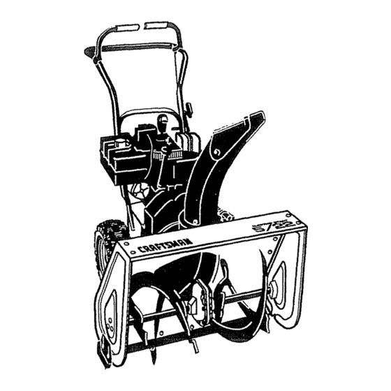
5 HORSEPOWER
22" DUAL STAGE
SNOW THROWER
120V. ELECTRIC
START
• Assembly
• Operation
• Customer Responsibilities
• Service and Adjustments
Q Repair Parts
SEARS, ROEBUCK
AND CO., Hoffman Estates, IL
337440
05/17/95
®
60179 U.S.A.
Advertisement
Table of Contents

Related Manuals for Sears Craftsman 536.886121


Summary of Contents for Sears Craftsman 536.886121
- Page 1 OWN R'S MODEL NO. 536.886121 ® Caution: Read and Follow 5 HORSEPOWER All Safety Rules 22" DUAL STAGE and Instructions SNOW THROWER Before Operating This Equipment 120V. ELECTRIC START • Assembly • Operation • Customer Responsibilities • Service and Adjustments Q Repair Parts 60179 U.S.A.
- Page 2 SAFETY RULES CANNOT CONTACT SPARK PLUG PLACE WIRE WHERE CAUTION: ALWAYS DISCONNECT SPARK PLUG WIRE PREVENT ACCIDENTAL STARTING WHEN SETTING-UP, TRANSPORTING, ADJUSTING MAKING REPAIRS. IMPORTANT SAFETY STANDARDS REQUIRE OPERATOR PRESENCE CONTROLS MINIMIZE RISK OF INJURY. YOUR SNOW THROWER IS EQUIPPED WITH SUCH CONTROLS,...
- Page 3 ,l_lJIl_ II'l ..SAFETY RULES MAINTENANCE AND STORAGE Do not tun the engine indoors, except when starting the engine and for transporting the snow thrower in Check shear bolts and other bolts frequently for or out of the building. Open the outside doors; proper tightness to be sure the snow thrower exhaust fumesare dangerous (containing CARBON is in safe working condition...
- Page 4 Sears will repair, free of charge, any defect in material and workmanship_ If this Craftsman Snow Thrower is used for commercial or' rental purposes, this warranty applies for only 90 days from the date of purchase.
-
Page 5: Table Of Contents
OPERATION ............1 0-t 5 FEm_ RULES ........PRODUCT SPECIFICATIONS ......4 SERVICE AND ADJUSTMENTS ....I9-25 STO RAG E ............. CUSTOMER RESPONSIBILITIES ..4,16-t8 WARRANTY ............4 TROUBLE SHOOTING ..........TABLE OF CONTENTS ..........REPAIR PARTS (SNOW THROWER),,,. 28-39 INDEX .............. - Page 6 CONTENTS OF HARDWARE PACK CONTENTS OF PARTS BAG ......... ,,,,, ,,,,,,,,,,,,,,,,,, "2 - Spare Shear Bolts (1/4.20 x 1-3/4 In.) 1 - Knob With Threads (not shown actual size) *2 - Spare Spacers "2 - Spare 1t4 - 20 Locknuts 1 - Owner's manual (not shown 1 - Starter Molor Cord (not actual size)
- Page 7 ,,,,,i IIIIH,.I. II.I I I ,I Illll II ,/'/ I,,,,,,, ..TOOLS REQUIRED FOR ASSEMBLY ............LOWE HANDLE SHIFTER 1 - Knife (to cut carton and plastic ties) PLATE 2 - !12 inch wrenches (or adjustable wrenches) 2 - 9116 inch wrenches (or adjustable wrenches) 2 - 3/4 inch wrenches (or adjustable wrenches) t - Pliers (to spread cotter pin) Screwdriver...
- Page 8 HOW TO SET UP YOUR SNOW UPPER THROWER ® Your snow thrower is equipped with height adjust 11t32" FLATWASHER skids (See Fig_ 2) on the outside of the auger housing. To adjust the skid height for different conditions, see To Adjust Skid Height paragraph or] page 19.
- Page 9 TO iNSTALL SHIFTER LEVER KNOB @ Thread the shifter lever knob onto the threaded end of the shifter lever until it is snug against the hex nut and the lip is pointed toward the engine. Tighten the hex nut against the bottom o! the shift lever knob (See Fig.
- Page 10 ..i ii iillllIll I I,,11 I, ul Ill I ll,,I. KNOW YOUR SNOW THROWER READ THIS OWNER'S MANUAL AND SAFETY RULES BEFORE OPERATING YOUR SNOW THROWER= Compare the illustrationswith your snow thrower to familiarize yourself with the location of various controlsand adjustment&...
- Page 11 TION The operation of any snow thrower can result in foreign objects being thrown into the eyes, which can result in severe eye damage. Always wear safety glasses or eye shields while operating the snow thrower. We recommend standard safety glasses available at SEARS Retail Stores or Service Centers These symbols may appear on your unit°...
- Page 12 /1111 IIH, ATION TO MOVE FORWARD AND BACKWARD AUGER DRIVE TRACTION DRIVE LEVER LEVER @ To shift, re]easethe tractiondrive lever and movethe speed shifter lever to the speed you desire, Ground speed is determined by snow conditions,, Select the speed you desire by moving the speed shifter lever (eft intothe appropriatenotchon the shiftlever plate: Speeds 1, 2 - Wet, Heavy, Extra Deep Speed 3 - Light...
- Page 13 ,,,,,,,,,,,,,,,,,, ..............BEFORE STARTING THE ENGINE OIL FILL CAP/DIPSTICK ® If the snow thrower mustbe moved withoutthe aid of the engine, itis easier to pullthe snow thrower bythe handles rather than pushing Before you service or start the engine, familiarize yourself with the snow thrower Be sure you...
- Page 14 TO STOP ENGINE PRIMER ELECTRIC CHOKE BU'FI'ON CONTROL ® To stop engine, move the throttle control lever to STOP position and remove key Keep the key in a BUTTON safe place_The engine wiltnot startwithoutthe key_ TO START ENGINE (Electric Starter) Be sure that the engine has sufficient oil.
- Page 15 ........FROZEN STARTER CAUTION: NEVER ENGINE INDOORS OR IN ENCLOSED, POORLY tf the starter is frozen and will not turn engine: VENTILATED AREAS° ENGINE EXHAUST Pull as much rope out of the starter as possible CONTAINS CARBON MONOXIDE, AN ODORLESS AND DEADLY GAS. KEEP •...
- Page 16 CUSTOM ILITI J .,,,,,,,, ,,,uL..,,J, ....SCHEDULE SERVICE SERVICE RECORDS DATES Fill in dates as you complete Every I Every Every Each Before regular service After Before As First 2 Each Needed Season Storage hours Use Hours Hours Hours Check Engine Oil Level Change Engine Oil Tighten Al! Screws and Nuts...
- Page 17 ' CUSTO ..... ill ii ,,ll ,lllll,i,illllllllllllll i ILmT ES SNOW THROWER LUBRICATION - EVERY TEN HOURS ..AXLE @ Auger Shaft- For storage, lubricate auger shaft ( See Fig, 16) with a clinging type grease such as Lubriplate. When replacing shear bolts, remove shear bolts and AXLE lubricate auger shaft (see To Replace Shear Bolt paragraph on page 24).,...
- Page 18 ......................, ,, ,,,, ....... CUSTOM ILITIES LUBRICATION ..® Hex Shaft and Gears - Hex shaft and gears require no lubrication All bearings and bushings are lifetime lubricated and require no maintenance (See Fig. 18, page 17). NOTE: Any greasing or oiling of the above components can cause contamination of the friction wheel If the disc FIG.
- Page 19 • Loosen thecarriage bolts and nuts securingthe scraper bar to the auger housing. SPARK PLUG WIRE AND TiE BACK CAUTION: ALWAYS DISCONNECT THE ® Adjust the scraper bar to the proper position. AWAY FROM THE PLUG BEFORE MAK- @ Tighten the carriage bolts and nuts, making sure that ING ANY ADJUSTMENTS OR REPAIRS.
-
Page 20: Belt Guide
AUGER MUST REIN FULL LEVER FORWARD POSmON (Just Contacting Periodic adjustment of the cables may be required due to "Z" FITTING Plastic Bumper) WHEN normal stretch and wear on the belts. To check for correct CHECKING adjustment, the control lever must be in the full forward position, restingon the plasticbumper._ The control cables are correctly adjusted when the center of the "Z"... - Page 21 ..SE ....ADJ........TO REPLACE BELTS The drive belts on this snow thrower are of special construction and should be replaced with original equipment belts available from your nearest Sears Store or Service Center. You will need the assistance of a second person while replacing the belts.
- Page 22 ADJUST ..TS S ......Jl iiiii u i iiiiiii ,111,,,i / ,, ....: : : ........TO ADJUST THE BELT GUIDES ..........MOTOR MOUNT FRAME ® Disconnect the spark plug wire. PANEL ® Remove the belt cover by removing the screw and flatwasheron the leftand right hand sides See Fig 27, AUGER page 21_...
- Page 23 ADJUSTNIE TO REPLACE FRICTION WHEEL FRICTION BOLT WHEEL If the snow thrower willnot move forward, and the friclion LOCKWASHER wheel is worn or damaged, you need to replace it as follows: (First allow the engine to cool.) SHAFT CAUTION: DRAIN GASOLINEOUTDOORS AWAY FROM FIRE OR FLAME.
-
Page 24: Carburetor
ADJUST E TS TO REPLACE AUGER SHEAR BOLT The augers are secured to the auger shaft with special bolts (See Fig°34) that are designed to break (to protect the machine) ff an object becomes lodged in the auger housing. Use of a harder bolt will destroy the protection provided by the shear bolt.. - Page 25 TO ADJUST OR REPLACE THE SPARK PLUG ,030 GAP If you have difficultystartingyoursnow thrower,you may need to adjust or replace the spark plug Follow the instructions below,, Replace the spark plug if the electrodes are pitted or burned or if the porcelain is cracked TO ADJUST: @ Clean the spark plug by carefully scraping the elec- trodes (do not sand blast or use a wire brush).
-
Page 26: Storage
Fig, 37)_ tf you do not wantto remove gasoline, a fuel stabilizer (such as Craftsman Fuel Stabilizer No_33500) may be added to any gasoline left in the tank to minimize gum deposits and acids., if the tank is almost empty,... - Page 27 ..TFIOU LE SHOOTINGPOI CORRECTION TROUBLE CAUSE Defective spark pfug Replace defective pfug Difficult starting Use carburetor bowl drain to flush and refiti with tresh Water or dirt in fuel system fuel, Clean fue! line; check fuel supply; add fresh Blocked fuel line or low on fuel Englne runs erratically fuel (gasofinetoi[ mixture il 2 cycle engine)
- Page 28 CRAFTSMAN 22" SNOW THROWER 536.886121 'E'LECTRICSTART.............. " ......REF. PART NO. PART NAME ,,,,,,,,, 33o783 MOTOR, ELECTRic STARTER SCREW, I/4.2oX_5o 6216 6217 SCREW, #6-32X2 50 HHC 6219 CORD, STARTER MOTOR 337440 OWNER'S MANUAL (NOT ILLUSTRATED) 319051A...
- Page 29 ,,,, ENGINE COMPONENTS REPAIR PARTS RER ITEM 1, PAGE 30 REF. ITEM 17, PAGE 31 PART NO, PART NAME ENGINE, CRAFTSMAN i43.965003 (SEE ENGINE REPAIR PARTS LIST) 302636 SCREW, 5t16-18X1.25 120638 WASHER, HVSPTLK ..328X.60X,09 3949 GUIDE, ROD BELT RH 578733...
- Page 30 CRAFTSMAN 22" SNOW THROWER 536.886121 FRAME COMPONENTS REPAIR PARTS REF. REF. PART NO, PART NAME PART NO. PART NAME H,,, .. 1,111 i1 336740-854 FRAME, ASSY 585474 BRNG, SLEV ,5201DX .70 ODX .65 910828 SCREW, 5/16-24Xl .00 585460 BRACKET, BRAKE ARM...
- Page 31 CRAFTSMAN 22" SNOW THROWER 536.886121 DRIVE cOMPONENTS REPAIR R_FF.; PART NO. PARTNAME PART NO. PART NAME 580961 579941 LEVER, ASSY TRACT CLUTCH PULLEY, V3L 650X 56 580965 313853 WASHER, WAVE BRNG, FLANGE 1084 137185 PIN, COTTER WASHER, FLAT ,281X1,00Xo063 313919...
- Page 32 CRAFTSMAN 22" SNOW THROWER 536.886121 REF_ REF_ PART NO. PART NAME PART NO. PART NAME iNO, ill ill =U/U=U/LL IIIIIIII g,lllllllll 10577 CASE, GEAR RH 51279 GASKET, GEAR CASE 10576 CASE, GEAR LH 51405 GEAR, WORM t8Q020 SCREW, t/4-20X _75...
- Page 33 CRAFTSMAN 22" SNOW THROWER 536.886121 AUGER HOUSING REPAIR PAR'Ts ... REF. REF. PART NAME PART NO. PART NAME PART NO. 58.3124 120380 WASHER, REGSPTLK PULLEY, V4L 622X ,67 120375 577400 NUT, 1/4-20 REGHEX SCREW, 5/16-18X .63 305205-830 AUGER, ASSY LH 71371 KEY, SQUARE ..18SQX 88LG...
- Page 34 CRAFTSMAN 22" SNOW THROWER 536.886121 DISCHARGE CHUTE REPAIR PARTS ..............,, I .1" l>.,,_J!l! "_,K PART NO, PART NAME IllL,± ..ImlC'UU ..1!780_830 CHUTE, UPR 305216 PIN, HINGE 70993 BOLT, 5f16q 8X ,75 CARRLN 12021 WASHER, PLASTIC 6711 WASHER, PLASTIC...
- Page 35 CRAFTSMAN 22" SNOW THROWER 536.886121 lllllr,,H Hi l lll WHEEL ASSEMBLY REPAIR PARTS PART NAME PART NO. 580883 SHAFT, AXLE 583012 SPROCKET & HUB, ASSY 73839 SCREW, I/4-20)(2.25 1502 NUT, t14-20 REGHEXCTRLK 581730 BEARING, FLANGE 579867 CHAIN, ROLLER #42 X 40P 73840 WASHER, FLAT .765X1 _12X06...
- Page 36 CRAFTSMAN 22" SNOW THROWER 536.886121 HANDLE ASSEMBLY REPAIR PARTS ........ RF_,, PART NAME PART NO, PART NAME PART NO, 9552-830 HANDLE, UPPER 1579 CABLE, CLUTCH 11234 SCREW, 5116-t 8X275 579869 SPRING, TENSION 120393 WASHER, FLAT .344X .69X_065 1673 SPRING, AUGER CLUTCH 120638 WASHER, HVSPTLK .328X 60X.09...
- Page 37 CRAFTSMAN 22" SNOW THROWER 536.886121 SHIFT YOKE REPAIR PARTS REF. ITEM 16, PAGE 36 REF. ITEM 1, PAGE 29 REF. ITEM 1, PAGE 30 REF. PART NO. PART NAME 580769-830 ROD, SHIFT SELECTOR 51332 SCREW, 1/4-20X 63WDFLLK t502 NUT, 1/4-20 REGHEXCTRLK...
- Page 38 CRAFTSMAN 22" SNOW THROWER 536.886121 CHUTE CONTROL ROD REPAIR PARTS Pt_Fi PART NAME PART NO. PART NAME PARr NO....585195 BRKT, WORM MTG 585426 CRANK, ASSY W/YOKE 585196 WORM, GEAR CHUTE 307399 HANDLE, CHUTE CRANK 304552 BLOCK, UNIVERSAL PIVOT...
- Page 39 70141 DECAL, DANGER AUGER FOOT 313892 DANGER CHUTE DECAL VIEW FROM AUGER 302922 DECAL, DANGER ENGLISH FRAME REAR 3O8766 DECAL, CRAFTSMAN 334151 DECAL, EL STR 5/22 337443 DECAL, DANG STRIPE 3902 DECAL, TRACTION DRIVE ENGAGE 3903 DECAL, AUGER DRIVE ENGAGE...
- Page 40 CRAFTSMAN 4-CYCLE ENGINE MODEL NUMBER 143.965003 310_ 307"_ 305/! "r., L206 > 93 / 287 390...
- Page 41 CRAFTSMAN 4-CYCLE ENGINE MODEL NUMBER 143.965003 DESCRIPTION ..........KEY# PART# KEY# PART# DESCRIPTION ........... 27234A Valve Cover Gasket ....... 36469A 27666 Breather Body ........Cylinder (incl 2, 20, &72) ......1 Breather Element ......26727 Dowel Pin ............ 2 31410 Valve cover ......
- Page 42 CARBURETOR NO. 632107A KEY# PART# DESCRIPTION 631615 Thrett_eShaft & Lever Assembly 631767 Throttle Return Spring ..631036 Throttle Shutter ....650506 Shutter Screw ......632108 Choke Shaft & Lever Assembly. 631815 Choke Shutter ......630735 Choke Positioning Spring ..631807 Fuel Fitting ........
- Page 43 STARTER MOTOR NO 33290D <3_gL'_ ,_ tr "- KEY# PART# DESCRIPTION 31749 Retainer Ring ........33522 Spring Retainer ..........33769 Anti-drift Spring........33524 Nut & Gear ............1 35461 Drive End cap Ass'y, (lncl 7) ......1 35450 "O" Ring .............. 2 35912 Armature ............
-
Page 44: Replacement
CRRFTSMRN® 5 HORSEPOWER OWNER'S 22" DUAL STAGE MANUAL SNOW THROWER 120V. ELECTRIC START MODEL NO. Each SNOW THROWER has its own MODEL NUMBER found on the engine mount frame.. 536,886121 Each ENGINE has its own MODEL NUMBER found on the BLOWER HOUSING. Always mention these MODEL NUMBERS when requesting service or Repair Parts foryourSNOW THROWER. - Page 45 MANUAL IMPORTANTE NO LO BOTE AL DEL PROPIETA MODELO NO. ;121 Precaucion: Lea y siga todas las reglas e instrucciones 5 CABALLOS DE FUERZA de seguridad antes de operar este equipo DOS ETAPAS,56 CM (22 PULGADAS) REMOVEDORA DE NIEVE ARRANQUE ELECTRICO •...
- Page 46 iiiii REGLAS DE SEGURIDAD ii/1/1_1/i ..... PRECAUCION: SIEMPRE DESCONECTE EL ALAMBRE DE LA BUJIA Y COLOQUELO DONDE NO HAGA CONTACTO CON L BUJIA PARA EVITAR ARRANQUE ACCIDENTAL MONTAR, TRANSPORTAR, AJUSTAR O EFECTUAR REPARACIONES+ IMPORTANTE LOS ESTANDARES DE SUGURIDAD REQUIEREN LA PRESENCIA DEL OPERADOR EN LOS CONTROLES...
- Page 47 ......REGLAS DE SEGuRIDAD ..17. Nunca opera la removedora de nteve sin buena 6o A! limplar, reparar, o Inspecctonar Is mdqulna visib|lldad o Iiumlnaclbno S[empre est_ seguro de su asegdrese de qua el barrenolpropulsor y toda parts estabittdad, y mantenga un agar re firms de fasmanijas. m6vll se hayan dstenido.
- Page 48 REMOVEDORA DE NIEVE CRAFTSMAN Durante dos athosa partir de la fecha de compra, cuando esta Removedora de nieve Craftsman sea mantenida, lubricada y afinada de acuerdo con las instruccionesen el manual del propietario, Sears reparar&, sin recargo alguno, cualquier defecto en materia!es y mano de obr&...
- Page 49 TABLA DE CONTENIDOS MONTAJE ............... REGLAS DE SEGUR1DAD ......2,3 OPERACION ..........10-16 ESPECIFICACtONES DEL PRODUCTO ..4 SERVICIO Y AJUSTES ........ 20-26 RESPONSABILIDADES DEL CLIENTE ..ALMACENAMIENTO ......................4,17-19 SOLUCtON DE PROBLEMAS .......28 GARANTIA ............. PEDIDO/SERVICIO DE PtEZAS ......TABLA DE CONTENIDOS .......
- Page 50 ...._ ill i i iillll i, CONTENIDO DEL PAQUETE CON ARTICULOS DE FERRETERIA Contenido de la bolsa con ias partes * 2 - Pernos de seguro por esfuerzo cortante de repuesto (1/4-20 x 1-3/4 pulgadas) Instructivo del usuario 1- PeriUade rosca "2- Espaciadores de repuestos (114-20) * 2 - Tuercas de seguridad...
- Page 51 TAJE HERRAIVIENTAS REQUERIDAS PARA EL MONTAJE Cuchilo para cortar la caja y las amarras pt_sticas Llaves de 1,3 cm (1/2 pulgada) o laves aiustables Llaves de t,4 cm (9116pulgada) o laves ajustables Llaves de 1,9 cm (314 pu?gada) o laves ajustables Afcate (para abrir el pasador) Destornilador Cinta m6trica o regla...
- Page 52 ....i i illll iil_i,iiii, i ,ill ii LI i iilllllllllllll illl_llll MONTAJE IIU,,I COMe INSTALAR SU REMOVEDORA MANIJASUPERIOR DE NIEVE ARANDELA PLANA Este equipo cuentacon unacorredera de apoyo (vea la Fig DE 8,7 MM (11/32 2) colocadaen laparte exteriordel atojamiento delbarreno. TUERCA HEXAGONAL Para ajustar lacorrederade apoyo a condicionesdiferentes, DE 7,9 MM (5/16...
- Page 53 MONTAJE PARA INSTALAR LA PERILLA DE LA PALANCA DE CAIVIBIOS ® Enrosque la perilla en el extremo roscadode la palanca de cambtos hasta que haga contactoconla tuerca hexagonal y la leng_eta apunte hacia el motor° Apriete la tuerca hexagonal contra el rondo de la perilla (vea !a Fig 6). PARA INSPECCIONAR/AJUSTAR CABLES DE CONTROL DEL EMBRAGUE...
- Page 54 OPERACION CONOZCA SU REMOVEDORA DE NIEVE LEA ESTE MANUAL DEL PROPIETARIO Y LAS REGLAS DE SEGURIDAD ANTES DE OPERAR SU REMOVEDORA DE NIEVE.. Compare las ilustraciones con su removedora de nieve pars _amilarizarse con ias posiciones de los diversos controles y ajustes. Guarde este manual para fferencia en el futuro.
- Page 55 ......_1 _ i,iiiiiin1111 ......i i iii ,1,1,11,1,1 La operaciSn de cuatquier removedora de nieve puede ocasionar que objetos extraSos sean lanzados dentro de sus oios, Io cual podr|a resuftar en daSos severos a los ojos. Use siempre galas de seguridad o protectores para los ojos mientras opera la removedora de nieve,, Se recomiendan las galas de seguridad est&ndar o la m&scara de seguridad de visiSn amplia para usada sobre los anteojos disponibles en todas las tiendas Centro de Servicios SEARS.
- Page 56 PARA IVIOVERSE HACIA ADELANTE Y PALANCA DE PROPULSION PALANCA DE PROPULSION HACIA ATRAS DE ORUGA DEL BARRENO ® Para cambiar de velocidad, sueite la palanca de propulsi6n de oruga y mueva la palanca de cambio de velocidades a la velocidad deseada. La velocidad en el terreno estar,_ determinada por las condicionesde la nieve.
- Page 57 illl OPERAC|O ANTES DE ENCENDER EL MOTOR TAPAbERAPCARiLLA MEDIDOR; _, DEL ....NIVEL DE ACEITE Si necesita mover la m_,quina removedora sin encender el motor, resultar& m_s f&cil moverta ha!_ndola hacia atr_s mientras agarra la manija, en vez de empujarla, Antes de dar servicio o encender el motor, tamiliar[cese con su m_quina removedora., Aseg0rese de conocer la ubicaci6n y entender la funci6n de todos los controles,...
- Page 58 OPERACION PARA PARAR EL MOTOR ® Pare parar la maroha del motor, mueva la paianca de control de la aceleraci6n a la posici6n PARAR (STOP) y retire la llave. Mantenga la Have en un lugar segum El motor no arrancara sin la Ilaveo PARA ARRANCAR EL MOTOR (Arrancador...
- Page 59 ® Mientrasmantienetapadoetrespiradero.presioneelbot,Sn PRECAUCION: NUNCA PONGA EL MOTOR EN cebo de Ia siguiente manera (retire el dedo det bot6n cebo MARCHA Eli AMBIENTES INTERIORES O EN despu_s de presionaflo): AREAS ENCERRADAS, MALVENTILADAS_ EL No optima el bot6n sila temperatura es superior a los ESCAPE DEL MOTOR CONTIENE MONOXIDO 10°c (5o°F) DE CARBONO, UN GAS INODORO Y LETAL...
- Page 60 ..Illll II OPERACION PISTAS SOBRE LANZAiVUENTO DE ® En superficies de grava o roca triturada, posicione las NIEVE correderas de apoyo a 1-1/4 puigadas pot debajo de la barra raspadora (V_ase el p&rrafo "C6mo ajustar la altura de las correderas de apoyo" en la p&gina 20) Las rocas y ®...
- Page 61 L CLI JJlllllllllll IIIIIIIIIIIIIIIIIII iiiii i_l_ll_lllll_lllllllllllil ....iiiiiiiiiiiiiiii FECHAS REGISTROS PROGRAMA SERVICIO ../IIHIIJlIIII[II IIIIII SERVICIO Llene las fechas a modlda Despu6s Antes Cede10 Cada 25 Prlmero Antes de! que complete su servIc[o de las :lecads acuerdo hems horas de cads a[macenamtento temporadi...
- Page 62 ES EL CLIENTE LUBRJCACION =CADA DIEZ HORAS ® Eje del barreno - Cuando vaya a guardar la unidad, lubriqueel eje del barreno (yea la Fig, 16) con una grasa de fijaci6n del tipo Lubrip]ate_ Cuando cambie los pernos de seguro pot esfuerzo cortante, remu_valos y lubriqueel eje del barreno (Consult®...
- Page 63 L CLi LUBRICACION Eje hexagonal y engranajes - No requieren lubricaci6n alguna, Todas las partes m6vites est&n lubricadasde pot J;'ct',_ '__ ,_'._ DEL AC_ITE vida y no necesitan mantenimiento (yea la Fig,,18, page A'tP..,, "',p,_T_P" DEBERA ESTAR !8)_ _.A_(=r/_,_/r ENTRE LA "_'_'P.,_ MARCALLENO Y NOTA:...
- Page 64 Afloje los pernosde carruaje (empotramiento) y las tuercas PRECAUCION: SIEMPRE DESCONECTE EL que fijan la barra raspadora a] alojamiento del barreno ® Ajuste ta barra raspadora en su posiciSn correcta ALEJADO BUJIA ANTES ALAMBRE DE LA BUJIA Y AMARRELO EFECTUAR CUALESQUIERA AJUSTES Y ®...
- Page 65 SERVlCiOS Y AJUSTES....iiiii1,111, i i, ii ii II,,I,H,,,, /,,,,, , ,,,,,,,, ,,,,,, ... PARA AJUSTAR LOS CABLES DE LA PALANCA DE PALANCA DE CONTROL DEL EMBRAGUE CONTROL DEBER/_ PROPULSION ESTAR EN LA ORUGA POSIC|ON Se podr|a requerir et ajuste peri6dico de los cables debido al TOTALMENTE estiramiento normal yef desgaste an las correas.
- Page 66 Y AJ ir ..,_,,, j,,,, iii I IIILIll IIII IIII PARA REEMPLAZAR CORREAS JW/I iilHiilUil liil / Las correas de tracci6n de esta unidad son el tesuttado de una fabricaci6n especial y deben set substituidas con el raisin@tip@ de correas, disponibles en su tienda o Centro de Servicios Sears m&s cercano_ Usted necesitar_ la ayuda de otra persona mientras reemplaza GUARDACORREAS...
- Page 67 SERVlCiOS Y AJUST ......AJUSTE DE LAS GUIAS DE LAS CUB1ERTADEL MOTOR CORREAS PANEL DEL Su removedora de nieve tiene dos gulas de correa: una a la derechayotraa laizquierda. Despu_s decambiarlacorreadel avance, usted necesitar& ajustar una o las dos guIas. Haga 1o ALOJAMIENTO siguiente con cada correa: DELBARRENO...
- Page 68 Y AJ REEMPLAZO DE LA RUEDA DE PERNO FRICCION RUEDA DE FR;CCtON Si la removedora de nteve no adelanta y ta rueda de fricctbn presenta desgaste o daSo, usted necesita cambiarla come se indica a continuacidn:(DeJe prlmero reposar el motor haste qua enfde,) ESPAClOS ABIERTOS Y LEJOS DEL FUEGO PRECAUCION:...
- Page 69 iiiii J, l ll, l l,,l,,,,,,, ii ii i,,J, ll,,l,, VlCIOS Y AJ i l l,ll,i i i i,ll, i i ill Li ,l,i Lll i i H,, ..............PARA REEMPLAZAR EL PERNO DE SEGURO POR ESFUERZO PERNOSDE SEGURIDADPOR CORTANTE DEL BARRENO Los barrenos est&n asegurados at eje de transmfsi6n del barreno con pernos especiales (V_ase Fig.
- Page 70 u,,,,l,t i,,,,ii,,,, ,11,,,,,,,,,11, i J, SERVICIOS Y AJ i=l=l=l=l=,l, m,ll,=,,, i=l=l= i=l=l= i i ,l,llll, l ,lli i PARA AJUSTAR O REEMPLAZAR LA BUJIA ENTREHIERRO 0,030 Si tiene dificuttades al arrancar su removedora de nieve, podr_a neces_tar ajustar o reemplazar la buj[a. Siga las instrucciones que se presentan abajo: Reemplace la buj[a si los electrodosest&rt picados o quemados o si la porcelana est_ rajada,,...
- Page 71 (tal come el Estabilizador de combustible Craftsman No. 33500) a cuatquier gasoIina que deje en el tanque para de minimizar los dep6sitos de goma y dcidos. Si el tanque est& casi vaclo, mezcle el...
- Page 72 PUNTOS PARA LA SOLUCION DE PROBLEMAS PROBLEMA CORRECClON CAUSA Bujra defectuosa Reempfazar bujfa defectuosa Dlflcultad de arranque User vasija de drenaje del carburador pate laver y Ague o suciedad en el sistema de combustible relIenar con combustible fresco Limpiar la Ifnea de combustible; reviser la existencia de El motor fundonn Llnea de combustible btoqueada o poco combus- combustible;...
- Page 73 NOTAS...
- Page 74 NOTAS...
- Page 75 ..... I'HH Illll NOTAS...
- Page 76 MANUAL DEL PROPIETARIO 5 CABALLOS DE FUERZA DOS ETAPAS, 56 CM (22 PULGADAS) REMOVEDORA DE NIEVE MODELO NO. ARRANQUE ELI_CTRICO 536.886121 Cada REMOVEDORA DE NIEVE tiene su propio NUMERO DE MODELO en el marco de montaje del motor, Cada MOTOR tiene su propio NUMERO...