Table of Contents
Advertisement
OWNER'S
MANUAL
MODEL NO.
944.529821
Caution:
Read and fol low
all Safety Rules
and In struc tions
Be fore Op er at ing
This Equip ment
Sears Canada, Inc., Toronto, Ontario M5B 2B8
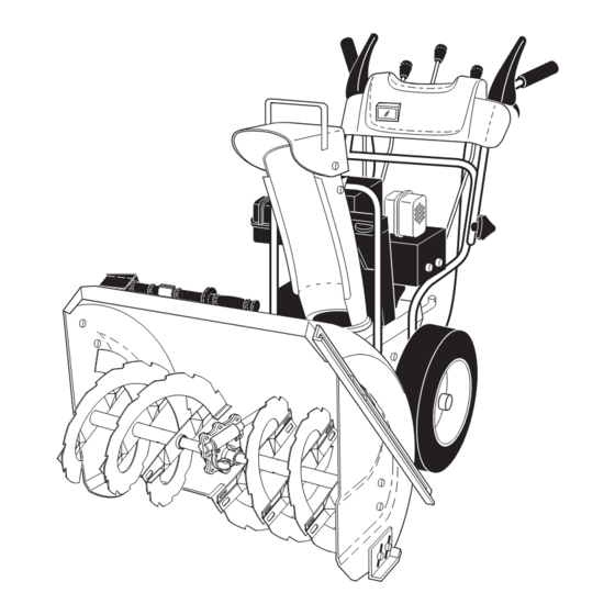
1550 SERIES B&S ENGINE
30" TWO-STAGE
POWER-PROPELLED
SNOW THROWER
• Assembly
• Operation
• Maintenance
• Service and Adjustments
• Repair Parts
Advertisement
Table of Contents

Related Manuals for Sears Craftsman 944.529821


Summary of Contents for Sears Craftsman 944.529821
- Page 1 30" TWO-STAGE all Safety Rules and In struc tions POWER-PROPELLED Be fore Op er at ing SNOW THROWER This Equip ment • Assembly • Operation • Maintenance • Service and Adjustments • Repair Parts Sears Canada, Inc., Toronto, Ontario M5B 2B8...
- Page 2 IMPORTANT Safe Operation Practices for Walk-Behind Snow Throwers This snow thrower is capable of amputating hands and feet and throwing objects. Failure to observe the following safety instructions could result in serious injury. WARNING: Snow throwers have ex- Look for this symbol to point out im- posed rotating parts, which can cause por tant safety precautions.
-
Page 3: Table Of Contents
Unleaded Regular only Should you experience any problem you cannot easily Oil Type SAE 5W-30 or 10W-30 remedy, please contact your nearest Sears service center/ (API SG–SL): (0°F to +40°F / –18°C to +5°C) department. We have competent, well-trained tech ni cians Synthetic SAE 5W-30 or 10W-30 and the prop er tools to service or repair this unit. -
Page 4: Customer Responsibilities
THIS PARAGRAPH SHALL NOT APPLY, BUT THE REMAINING PROVISIONS OF THIS DOCUMENT SHALL REMAIN VALID. SEARS retains the exclusive right to repair or replace the product or offer a full refund of the purchase price at its sole discretion. SUCH REMEDY SHALL BE YOUR SOLE AND EXCLUSIVE REMEDY FOR ANY BREACH OF WARRANTY. - Page 5 PARTS PACKED SEPARATELY IN CARTON (1) FUEL STABILIZER PACKET (1) MULTI- WRENCH (180684) (1) POWER CORD SAFTEY IGNITION KEY (S) (198563) (193071) (1) AUGER CONTROL ROD (1) DISCHARGE CHUTE EXTRA SHEAR BOLTS AND NUTS (2) SHOULDER (2) LOCKNUTS BOLT 1/4-20 x 1-3/4 1/4-20 (192090) (73800400)
- Page 6 ASSEMBLY / PRE-OPERATION Read these instructions and this manual in its entirety before you attempt to assemble or operate your new SPEED snow thrower. Reading the entire manual will familiar- CONTROL ize you with the unit, which will assist you in assembly, operation and maintenance of the product.
-
Page 7: Assembly / Pre-Operation
ASSEMBLY / PRE-OPERATION INSTALL TRACTION DRIVE CONTROL ROD INSTALL AUGER CONTROL ROD (See Figs. 5 and 6) (See Figs. 3 and 4) 1. Retrieve vinyl sleeve and spring from bag of parts and retrieve the auger control rod from carton chute tray. The traction drive control rod is installed on the snow Slide straight rod end through the small hole in the thrower. - Page 8 ASSEMBLY / PRE-OPERATION INSTALL DISCHARGE CHUTE / CHUTE ROTATOR INSTALL CHUTE DEFLECTOR REMOTE CONTROL HEAD (See Fig. 7) (See Figs. 8 and 9) NOTE: The multi-wrench provided in your parts bag may 1. Install remote cable bracket to discharge chute with 5/16-18 carriage bolt and 5/16-18 locknut as shown.
-
Page 9: Safety Rules
OPERATION KNOW YOUR SNOW THROWER READ THIS OWNER'S MANUAL AND ALL SAFETY RULES BEFORE OPERATING YOUR SNOW THROWER. Compare the illustrations with your snow thrower to familiarize yourself with the location of various controls and adjustments. Save this manual for future reference. These symbols may appear on your snow thrower or in literature supplied with the product. -
Page 10: Operation
OPERATION AUGER DISCHARGE CHUTE CONTROL LEVER GAS O LINE ELECTRIC CONTROL FILLER CAP START LEVER DEFLECTOR REMOTE DRIVE SPEED BUTTON CON TROL LEVER CONTROL LEVER MUF FLER RECOIL (AUXILIARY) STARTER HANDLE CHUTE CHOKE DE FLEC TOR CON- TRACTION TROL DRIVE CONTROL LEVER PRIM ER... - Page 11 OPERATION The operation of any snow thrower can result WARNING: If the discharge chute or in foreign objects thrown into the eyes, which au ger become clogged, shut-off en gine can result in severe eye damage. Always wear and wait for all moving parts to stop. Use safety glasses or eye shields while operating the clean-out tool, NOT YOUR HANDS, your snow thrower or performing any ad just-...
- Page 12 OPERATION • Slower speeds are for heavier snow and faster speeds USING THE CLEAN-OUT TOOL (See Fig. 15) are for light snow and transporting the snow thrower. It In certain snow conditions, the discharge chute may be- is recommended that you use a slower speed until you come clogged with ice and snow.
-
Page 13: Before Starting The Engine
OPERATION BEFORE STARTING THE ENGINE • If snow thrower must be operated over gravel surface, use extra caution and be sure skid plates are adjusted CHECK ENGINE OIL LEVEL (See Fig. 21) to lowest (highest scraper clear ance) position. The engine on your snow thrower has been shipped, from 1. - Page 14 OPERATION TO START ENGINE NOTE: Over priming may cause flooding, preventing the engine from starting. If you do flood the engine, wait a Your snow thrower engine is equipped with both a 120 Volt few minutes be fore at tempt ing to start and DO NOT push A.C.
- Page 15 OPERATION SNOW THROWING TIPS • Always operate the snow thrower with the engine at full throttle. Full throttle offers the best performance. • Go slower in deep, freezing or heavy wet snow. Use the drive speed control, NOT the throttle, to adjust speed. •...
-
Page 16: Warranty
MAINTENANCE GENERAL REC OM MEN DA TIONS LUBRICATION CHART The warranty on this snow thrower does not cover items SAE 5W-30 Motor Oil that have been sub ject ed to operator abuse or negligence. To receive full value from the warranty, operator must See “ENGINE”... -
Page 17: Product Specifications
MAINTENANCE TO CHANGE ENGINE OIL BELTS Check belts for deterioration and wear after every 50 hours Determine temperature range anticipated before next oil of operation and replace if necessary. The belts are not change. All oil must meet API service classification SG–SL. ad just able. -
Page 18: Service And Ad Just Ments
SERVICE AND ADJUSTMENTS To replace the capscrew/shear bolts: WARNING: To avoid serious injury, before 1. Disengage all controls and move throttle control to performing any service or ad just ments: STOP position. Wait for all moving parts to stop. 1. Be sure throttle is in STOP position. 2. -
Page 19: Service And Adjustments
(OEM) belts avail able from your nearest Sears service centre/department. Using other than OEM belts can cause 10. While your assistant slowly raises handles to rejoin personal injury or damage to the snow thrower. - Page 20 Your carburetor is not adjustable. Engine performance should not be affected at altitudes up to 2,134 meters. If your engine does not operate properly due to suspected carburetor problems, take your snow thrower to a Sears service center/department. ENGINE SPEED Never tamper with the engine governor, which is factory set for proper engine speed.
-
Page 21: Storage
STORAGE Immediately prepare your snow thrower for storage at • Empty the fuel tank by starting the engine and letting it run until the fuel lines and car bu re tor are empty. the end of the season or if the unit will not be used for 30 days or more. -
Page 22: Trou Ble Shoot Ing
TROUBLESHOOTING See appropriate section in manual unless directed to a Sears service center/department. PROBLEM CAUSE CORRECTION Does not start 1. Fuel shut-off valve (if so 1. Turn fuel shut-off valve to OPEN position. equipped) in OFF position. 2. Safety ignition switch OUT. - Page 23 SERVICE NOTES...
-
Page 24: Repair Parts
SNOW THROWER - - MODEL NUMBER 944.529821 REPAIR PARTS AUGER HOUSING / IMPELLER ASSEMBLY (EXPLODED) 01.07.026-C NOTE: All component dimensions given in U.S. inches. 1 inch = 25.4 mm IMPORTANT: Use only Original Equipment Manufacturer (O.E.M.) replacement parts. Failure to do so could be hazardous, damage your snow thrower and void your warranty. - Page 25 SNOW THROWER - - MODEL NUMBER 944.529821 REPAIR PARTS AUGER HOUSING / IMPELLER ASSEMBLY PART DESCRIPTION 175321X479 IMPELLER 427148 GEARBOX ASSEMBLY 188909 BEARING 427146 IMPELLER PULLEY 175322 DISCHARGE BASE 178675X008 CORNER BRACKET 192199 CLEAN OUT TOOL 405400 TOOL CLIP 73800400 NUT 1/4-20 74780426 SCREW 1/4-20 X .625...
- Page 26 SNOW THROWER - - MODEL NUMBER 944.529821 REPAIR PARTS AUGER HOUSING / IMPELLER ASSEMBLY 3 (5x) 4 (5x) PART DESCRIPTION 404930X428 AUGER HOUSING 404933X479 SCRAPPER BAR 01.07.003-A 72270505 CARRIAGE BOLT 5/16−18 X .625 155377 NUT 5/16−18 PART DESCRIPTION 420497X479 AUGER ASSEMBLY 30 LH 420498X479 AUGER ASSEMBLY 30 RH 01.07.019-A...
- Page 27 SNOW THROWER - - MODEL NUMBER 944.529821 REPAIR PARTS AUGER HOUSING / IMPELLER ASSEMBLY PART 01.07.024-B DESCRIPTION 420478 AUGER BEARING 411939 BEARING PLUG 179582 SCREW 5/16−18 X 1.00 PART DESCRIPTION 174762X479 SKID PLATE LH 178777X479 SKID PLATE RH 72270506 CARRIAGE BOLT 5/16−18 X .75 751153 NUT 5/16−18 01.11.001-A...
- Page 28 SNOW THROWER - - MODEL NUMBER 944.529821 REPAIR PARTS AUGER HOUSING / IMPELLER ASSEMBLY PART 01.16.001-A DESCRIPTION 181160X479 DRIFT CUTTER BAR 72270506 CARRIAGE BOLT 5/16−18 X .750 179246 PLASTIC WASHER 10040500 LOCKWASHER 5/16 128638 NUT 5/16−18 NOTE: All component dimensions given in U.S. inches. 1 inch = 25.4 mm IMPORTANT: Use only Original Equipment Manufacturer (O.E.M.) replacement parts.
- Page 29 SNOW THROWER - - MODEL NUMBER 944.529821 REPAIR PARTS CONTROL PANEL / DISCHARGE CHUTE PART DESCRIPTION 420315X428 CHUTE WELDMENT 178633X428 DEFLECTOR WELDMENT 420673 DEFLECTOR CONTROL ASSEMBLY 420325 DEFLECTOR SEAL 414280 KNOB BLACK 128415 POP RIVET 17501010 SCREW 10-24 X .625 179829 SHOULDER SCREW 191730...
- Page 30 SNOW THROWER - - MODEL NUMBER 944.529821 REPAIR PARTS CONTROL PANEL / DISCHARGE CHUTE PART DESCRIPTION 428272 LEVER/CABLE ROTATOR ASSEMBLY 17501010 SCREW 10-24 X .625 420678 ROTATOR HEAD 01.09.010-A 405932 ROTATOR PIVOT BRACKET 420675 PULLEY PIVOT 428273 CABLE ASSEMBLY ADJUSTABLE 428310 CABLE ASSEMBLY HEAT SHIELD NOTES:...
- Page 31 SNOW THROWER - - MODEL NUMBER 944.529821 REPAIR PARTS HANDLES PART DESCRIPTION 419800X479 PLOW HANDLE LH 419801X479 PLOW HANDLE RH 196944X007 PANEL BRACKET LH 196943X007 PANEL BRACKET RH 414515 HEATED HANDLE GRIP 74780512 CREW 5/16−18 X .750 74780524 SCREW 5/16−18 X 1.50 751153 NUT 5/16−18 155415...
- Page 32 SNOW THROWER - - MODEL NUMBER 944.529821 REPAIR PARTS HANDLES 01.08.002-F PART DESCRIPTION 412683X479 CONTROL PANEL 424517X479 CONTROL LEVER LH 424516X479 CONTROL LEVER RH 426917X008 TRACTION ROD ARM 426918X008 IMPELLER ROD ARM 412677 INTERLOCK ROD 421613 SPACER 169675 RETAINER 17060410 SCREW 1/4-20 X .62 414280 KNOB BLACK...
- Page 33 SNOW THROWER - - MODEL NUMBER 944.529821 REPAIR PARTS HANDLES PART DESCRIPTION 421763 IMPELLER ROD ASSEMBLY 429832 TRACTION ROD ASSEMBLY 187782 SHIFTER ROD TOP 187784 SHIFTER ROD BOTTOM 180447 SPRING SLEEVE 192091 SPRING SLEEVE 178669 IMPELLER SPRING 180926 TRACTION SPRING 72270505 CARRIAGE BOLT 5/16-18 X .750 155377...
- Page 34 SNOW THROWER - - MODEL NUMBER 944.529821 REPAIR PARTS HANDLES PART DESCRIPTION 419796X479 LOWER TUBE 418313X479 PIVOT SUPPORT 428867 BOLT 5/16-18 X .750 17000616 SCREW 3/8-16 X 1 .00 01.05.003-C PART DESCRIPTION 413927 CONSOLE PANEL BLACK 178668 HEADLIGHT BEZEL 178666 HALOGEN HEADLIGHT 184471 SHOULDER SCREW 10-24 X .625...
- Page 35 SNOW THROWER - - MODEL NUMBER 944.529821 REPAIR PARTS DRIVE 01.03.003-A PART DESCRIPTION 404308 AXLE SHAFT 187794 SPACER 174697 THRUST WASHER 179830 BEARING 146315 SCREW 5/16−18 X .625 17490508 BOLT 5/16−18 X .500 155443 CLIK PIN 74780632 SCREW 3/8−16 X 2.00 73800600 NUT 3/8−16 NOTE: All component dimensions given in U.S.
- Page 36 SNOW THROWER - - MODEL NUMBER 944.529821 REPAIR PARTS DRIVE 01.02.015-C NOTE: All component dimensions given in U.S. inches. 1 inch = 25.4 mm IMPORTANT: Use only Original Equipment Manufacturer (O.E.M.) replacement parts. Failure to do so could be hazardous, damage your snow thrower and void your warranty.
- Page 37 SNOW THROWER - - MODEL NUMBER 944.529821 REPAIR PARTS DRIVE PART DESCRIPTION 192002 SHIFT BRACKET 17501010 SCREW 10-24 X .625 74760552 SCREW 5/16-18 X 3.25 179246 PLASTIC WASHER 192001 SHIFT ASSEMBLY 155415 WASHER 192195 FRICTION SPRING 73800500 NUT 5/16-18 198247X008 FRONT CLUTCH BRACKET 405484 CONTROL ARM...
- Page 38 SNOW THROWER - - MODEL NUMBER 944.529821 REPAIR PARTS CHASSIS / ENGINE / PULLEYS PART DESCRIPTION - - - - - - B&S ENGINE MODEL 21M114-1362-E1 418696X428 FRAME 150406 BOLT 3/8-16 428867 SCREW 5/16-18 X .750 01.00.033-A PART DESCRIPTION 423185X428 ENGINE MOUNT PLATE 01-01-007-A NOTE: All component dimensions given in U.S.
- Page 39 SNOW THROWER - - MODEL NUMBER 944.529821 REPAIR PARTS CHASSIS / ENGINE / PULLEYS PART DESCRIPTION 409161 COVER ASSEMBLY 17490408 SCREW 1/4-20 X .50 01.21.013-A NOTE: All component dimensions given in U.S. inches. 1 inch = 25.4 mm IMPORTANT: Use only Original Equipment Manufacturer (O.E.M.) replacement parts. Failure to do so could be hazardous, damage your snow thrower and void your warranty.
- Page 40 SNOW THROWER - - MODEL NUMBER 944.529821 REPAIR PARTS CHASSIS / ENGINE / PULLEYS 01.21.009-B PART PART DESCRIPTION DESCRIPTION 408007 IMPELLER BELT 59289 WASHER 192383 TRACTION BELT 73800500 NUT 5/16-18 423723X479 IDLER ARM BRACKET 74780520 SCREW 5/16-18 X 1 .25 180523 IDLER PULLEY 851084...
- Page 41 SNOW THROWER - - MODEL NUMBER 944.529821 REPAIR PARTS WHEELS 01.15.001-A PART DESCRIPTION 405161 COVER 184471 SHOULDER SCREW 12000045 RETAINER RING 192126 WHEEL DRIVER 182466 RETAINER RING 187622 WHEEL LOBE 194941 CLUTCH SLIDE 179139 SPRING 189282 SQUARE KEY 194940 AXLE LOBE 174697 THRUST WASHER 193506X479...
- Page 42 SNOW THROWER - - MODEL NUMBER 944.529821 REPAIR PARTS WHEELS PART DESCRIPTION 185602X004 STEER CABLE BRACKET LH 185603X479 STEER CABLE BRACKET RH 01.15.002-A PART DESCRIPTION 196752X421 WHEEL ASSEMBLY LH 196753X421 WHEEL ASSEMBLY RH 01.06.006-A NOTE: All component dimensions given in U.S. inches. 1 inch = 25.4 mm IMPORTANT: Use only Original Equipment Manufacturer (O.E.M.) replacement parts.
- Page 43 SNOW THROWER - - MODEL NUMBER 944.529821 REPAIR PARTS BAG OF PARTS PART DESCRIPTION 198563 POWER CORD 169675 RETAINER PIN 180684 WRENCH 184505 REMOTE SPRING 179829 SHOULDER BOLT 1/4-20 191730 LOCKNUT 1/4-20 72250505 CARRIAGE BOLT 5/16-18 X 5/8 751153 LOCKNUT 5/16-18 73800600 LOCKNUT 3/8-16 19131316...
- Page 44 SNOW THROWER - - MODEL NUMBER 944.529821 REPAIR PARTS DECAL PART DESCRIPTION 181037 DECAL, DANGER 181035 DECAL, DANGER, DEFLECTOR 181042 DECAL, DANGER 181033 DECAL, INSTRUCTION 415475 DECAL, SPEED CONTROL 183730 DECAL, REMOTE DEFLECTOR 415399 DECAL, LH TRIGGER 415398 DECAL, RH TRIGGER 415455 DECAL, CONSOLE, HYDRO 428960...
- Page 45 SERVICE NOTES...
- Page 46 BRIGGS & STRATTON 4-CYCLE EN GINE MODEL NUMBER 21M114-1362-E1...
- Page 47 BRIGGS & STRATTON 4-CYCLE EN GINE MODEL NUMBER 21M114-1362-E1...
- Page 48 BRIGGS & STRATTON 4-CYCLE EN GINE MODEL NUMBER 21M114-1362-E1 PART PART DESCRIPTION DESCRIPTION 794850 CYLINDER ASSEMBLY 796128 Ø JET-MAIN (HIGH ALTITUDE) 698340 KIT-BUSHING/SEAL 796137 KIT-CARBURETOR OVERHAUL (MAGNETO SIDE) 796315 Ø SPACER-CARBURETOR 391086S • SEAL-OIL (MAGNETO SIDE) 796122 CARBURETOR 794871 HEAD-CYLINDER 690727 Ø...
- Page 49 BRIGGS & STRATTON 4-CYCLE EN GINE MODEL NUMBER 21M114-1362-E1 PART PART DESCRIPTION DESCRIPTION 793006 HOSE-PRIMER 696709 GUARD-REWIND 791822 GROMMET 795027 CAP-FUEL 694674 BUSHING-GOVERNOR CRANK 957A 698109 CAP-FUEL 793216 BOLT (GOVERNOR CONTROL 694260 TANK-FUEL LEVER) 698783 BOWL-FLOAT 699854 SCREW (CONTROL COVER) 793382 PRIMER-CARBURETOR 691696...
- Page 50 BRIGGS & STRATTON 4-CYCLE EN GINE MODEL NUMBER 21M114-1362-E1 Engine Power Rating Information The gross power rating for individual gas engine models is labeled in accordance with SAE (Society of Automo-tive Engineers) code J11940 (Small Engine Power & Torque Rating Procedure), and rating performance has been obtained and corrected in accordance with SAE J1995 (Revision 2002-5).
- Page 51 SERVICE NOTES...
- Page 52 02488 428960 08.12.09 SR Printed in U.S.A.