Advertisement
-i 850
Operator's Manual
Edger
Models 550
551
IMPORTANT:
READ SAFETY RULES AND INSTRUCTIONS
CAREFULLY
Warning:
This unit is equipped with an internal combustion engine and should not be used on or near any unimproved
forest-
covered, brush-covered
or grass-covered
land unless the engine's exhaust system is equipped with a spark attester meeting
applicable
local or state laws (if any). If a spark arrester is used, it should be maintained
in effective working order by the operator.
In the State of California the above is required by law (Section 4442 of the California Public Resources Code). Other states may have
similar laws. Federal laws apply on federal lands. A spark arrester for the muffler is available through your nearest engine authorized
service dealer or contact the service department,
P.O. Box 361131 Cleveland, Ohio 44136-0019.
Troy-Bilt LLC, P.O. BOX 361131 CLEVELAND,
OHIO 44136-0019
PRINTED IN U.S.A.
FORM NO. 769-00566
(11/02)
Advertisement
Table of Contents

Related Manuals for Bolens 550

Summary of Contents for Bolens 550
- Page 1 -i 850 Operator's Manual Edger Models 550 IMPORTANT: READ SAFETY RULES AND INSTRUCTIONS CAREFULLY Warning: This unit is equipped with an internal combustion engine and should not be used on or near any unimproved forest- covered, brush-covered or grass-covered land unless the engine's exhaust system is equipped with a spark attester meeting applicable local or state laws (if any).
-
Page 2: Table Of Contents
TABLEOFCONTENTS Content Page Important Safe Operation Practices ..............Assembling The Edger ..................Know The Edger ....................Operating The Edger ..................Making Adjustments ................... Maintaining and Servicing The Edger ..............Off Season Storage .................... Troubleshooting ....................Parts List ......................FINDINGMODEL NUMBER This Operator's Manual is an important part of your new edger. -
Page 3: Important Safe Operation Practices
SECTION 1: IMPORTANT SAFEOPERATION P RACTICES WARNING: THIS SYMBOL POINTS OUT IMPORTANT SAFETY INSTRUCTIONS WHICH, IF NOT FOLLOWED, COULD ENDANGER THE PERSONAL SAFETY AND/OR PROPERTY OF YOURSELF AND OTHERS. READ AND FOLLOW ALL INSTRUCTIONS IN THIS MANUAL BEFORE ATTEMPTING TO OPERATE THIS MACHINE. FAILURE TO COMPLY WITH THESE INSTRUCTIONS MAY RESULT IN PERSONAL INJURY. - Page 4 4. Never o perate withdamaged s afety devices. 18. Onlyusepartsandaccessories made forthis Failure todoso,canresult i n personal injury. machine bythemanufacturer. Failure todoso,can 5. Neverrunanengine indoors orina poorly result i npersonal injury. 19. If situations o ccurwhich arenotcovered inthis ventilated a rea.Engine exhaust contains carbon monoxide, anodorless a nddeadly gas.
-
Page 5: Assembling The Edger
SECTION 2: ASSEMBLING YOUR EDGER IMPORTANT: This unit is shipped WITHOUT Upper Handle GASOLINE or OIL. After setting up the unit, service engine with gasoline and oil as instructed in the separate engine manual packed with your unit. NOTE: Reference to right or left hand side of the edger is observed from the operating position. -
Page 6: Know The Edger
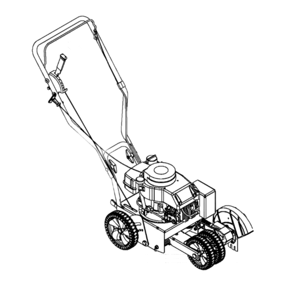
SECTION 3: KNOW THEEDGER Bail Blade Depth Control Lever (Transport Position Shown) Pull Rope / Recoil Starter Curb Height Adjustment Lever (If Equipped) Blade Adjustment Lever (If Equipped) Spindle Belt Guard NOTE: Wheel and blade styles vary by model. Yours may differ slightly. Figure 4 WARNING: Be familiar... -
Page 7: Operating The Edger
SECTION 4: OPERATING T HEEDGER The operation of any edger can result IMPORTANT: Using the primer to restart a warm engine in foreign objects being thrown into after a short shutdown is usually not necessary. Doing the eyes, which can result in severe so may result in a flooded engine. -
Page 8: Making Adjustments
SECTION 5: MAKING ADJUSTMENTS BladeTilt Adjustment ( models so Edging equipped) Set the blade adjustment lever (refer to Figure 5) in the center notch to place the edger blade in a 90 ° position for edging. See Figure 7. NOTE: Edgerfeatures varybymodeL Alledgermodels do NOT come equipped for blade tilt adjustment nor is... - Page 9 • Secure with the betl washer and the hex lock nut Remove the spindle belt guard by removing the two self tapping screws which secure it to the blade removed earlier. See Figure 11. plate assembly. See Figure 9. Blade Plate Bell Washer Figure 11 IMPORTANT: Use a torque wrench to tighten the hex...
-
Page 10: Maintaining And Servicing The Edger
• Lower theright,rearwheel b ymoving thecurb • Release thecurbheight a djustment lever t o lock height a djustment leverslightly totheleft.See thewheel i nposition. SeeFigure 13. Figure 12. Adjustment Lever Operating (Normal Position) Figure 12 wb Height Adjustment Lever Pivot the right, rear wheel into an applicable position in relation to the height of the curb to be edged along. -
Page 11: Replacing The Edger Blade
• Working infrontoftheedger, w iththerearwheels The edger drive belt is subject to wear and should be backed uptoa curbortheunittiltedbacktokeepit replaced if any signs of cracking, shredding or rotting fromrolling backwards, grasp thespindle belt g uard are present. To replace the belt, proceed as follows: withonehand andpushtowards t herearoftheunit •... -
Page 12: Off Season Storage
SECTION 7: OFF-SEASON S TORAGE Observe the following when preparing the edger for • Store the edger in a dry, clean area. Do not store long-term storage: next to any corrosive materials, such as lawn fertilizer. • Clean and lubricate unit thoroughly as instructed on •... -
Page 13: Parts List
SECTION 9: MODEL 550 AND551HANDLE PART REF. PART DESCRIPTION DESCRIPTION 710-0116 Screw, 5/16-18 736-0451 Saddle Washer,.320 ID x.93 OD 710-0449 Screw, 5/16-18 746-04036 Wheel Adjustment Cable 710-1205 Eye Bolt 746-04052 Control Cable (Tecumseh) 710-3008 Screw, 5/16-18 746-04035 Control Cable (Briggs & Stratton) 710-0606 Screw 747-0976A... - Page 14 Model550 And551Frame __12 j;. 4 PART DESCRIPTION 710-0191 Screw, 3/8-24 710-0599 Screw, 1/4-20 710-0654A Screw, 3/8-16 710-0944 Screw, 3/8-16 712-0431 Flange Lock Nut, 3/8-16 731-04168 Debris Guard 736-0320 Flat Washer, 3/8 ID x 1.37 OD 736-0452 Bell Washer,.396 x 1.140 736-3052 Flat Washer,.406 x 1.00 736-3090...
- Page 15 Model550 And551Spindle Assembly /JI.J v 13" V-BELTS are specially designed to engage ana disengage safely. A substitute tnon-OEM pV-Belt can be dangerous by not disengaging completely. PART PART DESCRIPTION DESCRIPTION 687-02019 736-3090 Flat Washer,.260 x.72 Blade Plate Assembly 737-3000 Lube Fitting, 3/16 710-0395 Hex Screw, 5/16-18 710-0599...
- Page 16 Model550 And551WheelAssembly (Frameshownforreference only) REF. PART DESCRIPTION 687-02022 Curb Height Adjustment Lever 712-0431 Flange Lock Nut, 3/8-16 732-04045 Torsion Spring 734-1987 Wheel 8xl .8 734-1988 Wheel 7xl .8 736-0182 Spring Washer,.500 x 1.00 736-0208 Flat Washer,.51 ID x 1.50D 736-0232 Wave Washer,.531 ID x.781 OD 736-0234 Washer,.385 x 1.5...
- Page 17 NOTES...
- Page 18 MANUFACTURER'S LIMITED WARRANTY FOR: The limited warranty set forth below is given by Troy-Bilt LLC Troy-Bilt LLC does not extend any warranty for with respect to new merchandise purchased and used in the products sold or exported outside of the United States, United States, its possessions and territories.