Advertisement
Quick Links
Camcorder Support
Support pour caméscope
手持式摄录一体机支架
Operating Instructions
Mode d'emploi
Manual de instrucciones
使用说明书
VCT-SP1BP
70
Printed on 70% or more recycled paper using VOC (Volatile
Organic Compound)-free vegetable oil based ink.
-1
1
2, 3
4
-2
-3 -4
2
3, 4
-1
-3
2
4
5
VOC
6
7, 8
2
3
1
VCT-H1BP
LANC
1
17
2
18
3
19
4
20
5
21
6
22
7
23
8
24
9
25
10
26
11
27
12
FOCUS
28
REC REVIEW
13
29
14
REC START/STOP
30
15
31
16
32
D
-1
1
OFF
BALANCE
ON
2
3
4
5
-2
1
2
3
V
4
-3
5 kg
1
2
3
4
LANC
-1
1
BALANCE
2
3
4
-2
-2
-3
1
2
D
3
4
5
6
7
8
-4
5 kg
VCT-M1BP
RM-1BP
1
2
3
LANC
4
5
English
Before operating the product, please
read this manual thoroughly and
retain it for future reference.
VCT-SP1BP Camcorder Support is
used for reducing the load on your
arms by distributing the weight of
your video camera to your shoulders
and waist.
WARNING
To reduce fire or shock hazard, do not
expose the unit to rain or moisture.
1
For the Customers in the U. S. A.
2
This device complies with Part 15 of
the FCC Rules. Operation is subject to
3
the following two conditions:
(1) this device may not cause harmful
4
interference, and
Carrying the Camcorder
(2) this device must accept any
interference received, including
Support
interference that may cause undesired
Do not lift up or move the Camcorder
operation.
Support by the remote cord.
Cleaning
CAUTION
You are cautioned that any changes or
modifications not expressly approved
in this manual could void your
authority to operate this equipment.
Note:
1
LANC
This equipment has been tested and
found to comply with the limits for
a Class B digital device, pursuant to
2
Part 15 of the FCC Rules.
These limits are designed to provide
Features
reasonable protection against
REC START/STOP
harmful interference in a residential
3
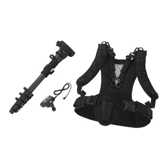
VCT-SP1BP Camcorder Support
installation. This equipment
consists of a monopod (VCT-M1BP),
generates, uses, and can radiate
remote commander (RM-1BP), and
radio frequency energy and, if not
harness (VCT-H1BP).
installed and used in accordance
When you use the harness, the weight
4
with the instructions, may cause
of your video camera and accessories
harmful interference to radio
attached to the video camera is
communications. However, there is
distributed to your shoulders and
no guarantee that interference will
waist, and the load on your arms
not occur in a particular installation.
is reduced. You can shoot a video
NORMAL
If this equipment does cause harmful
without difficulty even when you are
interference to radio or television
moving.
reception, which can be determined
You can also use Camcorder Support
by turning the equipment off and
as a monopod with a remote
on, the user is encouraged to try to
commander without wearing the
REVERSE
correct the interference by one or
harness.
more of the following measures:
About the remote commander
–
Reorient or relocate the receiving
antenna.
–
Increase the separation between the
equipment and receiver.
–
Connect the equipment into
an outlet on a circuit different
from that to which the receiver is
connected.
SLOW
–
Consult the dealer or an
experienced radio/TV technician
for help.
For the Customers in Canada
MID
This Class B digital apparatus
4
About the monopod
complies with Canadian ICES-003.
The monopod automatically
FAST
maintains stability for the video
For the Customers in Europe
8
camera in accordance with the tilt
angle by means of a counter balance.
Disposal of Waste Electrical
5
and Electronic Equipment
About the supplied camera
for business use (Applicable
mounting screw
FOCUS
If your video camera has the facility to
in the European Union and
use two camera mounting screws, use
other European countries with
the supplied camera mounting screw.
separate collection systems)
Identifying the Parts
6
REC REVIEW
1 Pin
2 Camera mounting shoe
3 Monopod head
4 Tilt lock lever
5 Camera mounting screw
This symbol on the product or on
6 Safety lock lever
its packaging indicates that this
7 Camera mounting shoe lock lever
product shall not be treated as
8 Counter balance switch lever
household waste. Instead it shall
HDV
DV
REC REVIEW
9 Hook holder
be handed over to the applicable
10 Remote cord
take-back scheme for the recycling of
11 Cord belt
electrical and electronic equipment.
12 FOCUS button
By ensuring this product is disposed
13 REC REVIEW button
of correctly, you will help prevent
14 REC START/STOP button
potential negative consequences for
15 Zoom lever
the environment and human health,
16 Zoom direction switch
which could otherwise be caused
17 Zoom speed switch
by inappropriate waste handling
18 Remote plug
of this product. The recycling of
19 Leg
materials will help to conserve
20 Leg length adjustment lock lever
natural resources. For more detailed
21 Clamp lever
information about recycling of this
product, please contact your local
22 Remote plug holder
23 Remote cord holder
Sony office or visit Sony Europe's web
24 Clamp
site for business customers:
25 Shoulder belt
http://www.sonybiz.net/environment
26 Support belt
This product with the CE marking
27 Adjuster
complies with the EMC Directive
28 Waist belt
issued by the Commission of the
29 Hook
European Community.
30 Monopod holder
Compliance with this directive
VCT-M1BP
31 Buckle
implies conformity to the following
32 D-ring
European standards:
5 kg
• EN55103-1 :Electromagnetic
Using the Monopod
Interference (Emission)
60
45
• EN55103-2 :Electromagnetic
1 670 mm
Susceptibility (Immunity)
This product is intended for use
522 mm
in the following Electromagnetic
Use the procedure below to attach
1.3 Kg
Environment(s):
your video camera to the monopod
5
E1 (residential), E2 (commercial and
without using the harness.
light industrial), E3 (urban outdoors)
RM-1BP)
and E4 (controlled EMC environment
-1 Preparing the monopod
ex. TV studio).
REC START/STOP
FOCUS
REC
1 Set the camera mounting shoe in a
Notice for the customers in the
REVIEW
countries applying EU Directives
Loosen the tilt lock lever.
The manufacturer of this product
62
80
105 mm
/
/
Press down the counter balance
is Sony Corporation, 1-7-1 Konan
Minato-ku Tokyo, 108-0075 Japan.
1 000 mm
The Authorized Representative for
100 g
EMC and product safety is Sony
Deutschland GmbH, Hedelfinger
VCT-H1BP
Strasse 61, 70327 Stuttgart, Germany.
320 mm
500 mm
350 mm
For any service or guarantee matters
After pressing down the counter
please refer to the addresses given
/
/
in separate service or guarantee
700 g
documents.
(1)
(1)
(1)
Confirm that the tilt spring is
Precautions on Use
(1)
(1)
(1)
Precautions on the remote
2 Loosen the leg length adjustment
commander
(1)
Do not drop the remote commander
or expose it to any liquid substance.
Handle the remote commander
3 Tighten the leg length adjustment
carefully.
Do not expose the remote
4 While holding down the safety
commander to direct sunlight. Do
not also keep it in a place subject
to high temperatures, such as near
a heating appliance or a place with
high humidity.
5 Place the monopod in a safe
Hold the remote plug straight when
you disconnect and connect it. If
1
you use too much force, the plug
could be damaged.
-2 Attaching the remote
Connecting and disconnecting
the video camera
1 Turn the clamp lever of the remote
Fix your video camera by firmly
tightening the tilt lock lever. Do
not attach accessories to the video
camera after mounting it on the
monopod head. Otherwise, the
2 Select the position on the leg at
monopod head could tilt and
damage the video camera.
When you attach the video camera
3 Align the center of the leg with the
to the monopod head, make sure
that monopod does not topple over.
Precautions on using the
monopod
When you use this Camcorder
Support, hold the video camera or
monopod with your hand.
4 Place the monopod in a safe
Firmly tighten and fix the parts to
be tightened such as the various
lock knobs and levers, monopod
VCT-SP1BP
lock lever, and camera mounting
-3 Mounting the video
screw.
After attaching the video camera
to the monopod, do not swing the
The total weight of the video camera
entire monopod or face it down.
and accessories that can be attached
To prevent the video camera from
to Camcorder Support is maximum
moving suddenly, do not operate the
5 kg (limit weight). Make sure that
counter balance switch lever when
the weight of video camera and
0570-00-2288
the video camera is attached to the
accessories does not exceed this limit.
monopod.
1 Install a battery pack, cassette, or
PHS
0466-31-2588
Extend or retract the leg or loosen
<FAX>
0466-31-2595
the leg length adjustment lock lever
carefully so that you do not get
9:00
18:00
your finger caught in the gap of the
segments.
http://www.sony.jp/
2 Attach the camera mounting shoe
3 Attach the video camera to the
If the remote commander cord is
monopod.
too long, fasten the cord to the shaft
with a cord belt.
Set the video camera on the
monopod head of the monopod
from the front edge of the camera
mounting shoe and lightly tap
the top of the camera. You will
hear a click as the camera is
attached to the monopod.
Push the camera mounting shoe
When you loosen the tilt lock lever
lock lever to the right to lock the
camera in place.
and perform tilting, the monopod
4 Connect the remote plug to the
may move jerkily. This is not a
Tilting
LANC
connector of the video
malfunction. Loosen the tilt lock
lever with a firm hand.
camera.
When you place monopod on the
If the remote commander cord
1 Make sure the counter balance
is too long, fasten the cord to the
switch lever pressed down to the
floor, make sure to place it in a
shaft with a cord belt.
right.
safe place so that it will not cause
2 Loosen the tilt lock lever.
anyone to trip over. Also, keep it
in such a way that its position will
3 Adjust the angle of the camera
Using the Monopod
not put excess load to the remote
mounting shoe as required.
commander.
with the Harness
4 Tighten the tilt lock lever.
Use the following procedure to use the
Cautions
monopod with the harness.
Never use the tilt lock lever to adjust
the torque weight. This could cause
When you use the monopod with
a trouble.
the leg extended, you can extend the
Before tilting, make sure to loosen
leg up to the third step (counting
When the Camcorder Support
the tilt lock lever.
from the camera mounting shoe).
becomes dirty, clean it with a soft
If you extend the leg farther than
cloth lightly moistened with a mild
the third step, the video camera will
Using the Remote
detergent solution. Then, wipe it
become unstable and this could
commander
clean with a dry cloth.
cause the camera to topple over or
After using the Camcorder Support
an injury.
Read the section below together with
on the beach or in places exposed
Use the third hook holders and
to sea breezes, wipe it clean with a
the operation instructions of the video
above (counting from the camera
dry cloth.
camera.
mounting shoe) to loop the support
1 Confirm that the remote plug
belt. If you use a hook holder lower
is connected to the LANC
than the third one, the video camera
(remote) connector of the video
will become unstable and this could
camera.
cause the camera to be topple over
or an injury.
2 Set the video camera to standby
mode.
See the operation instructions
of the video camera for further
information.
3 Press the REC START/STOP
button.
Video shooting will start. If you
press the button again, shooting
will stop (standby mode).
4 Zooming on an object.
a
Use the zoom direction switch to
select the zoom direction.
Tilt the zoom lever of the remote
a
commander.
NORMAL mode
You can use the remote commander
Clockwise/T side (telephoto):
by connecting it to video cameras
equipped with a LANC
Subject appears closer.
b
Counterclockwise/W side (wide
connector.
b
You can use the remote commander
angle):
for operation by attaching it to the
Subject appears farther away.
monopod using the clamp.
REVERSE mode
You can use the zoom direction
a: Use
Clockwise/W side (wide angle):
switch to change the zoom direction
b: Do not use
Subject appears farther away.
of the zoom lever.
Counterclockwise/T side
Do not use the monopod with an
You can use the zoom speed switch
(telephoto):
attached video camera when there
to change the zoom speed in three
is a person or an object directly
Subject appears closer.
levels.
under the video camera. If the video
On some video cameras, you may be
camera is not properly attached to
able to change the zooming speed
the monopod and falls off, it could
by using the zoom speed switch and
cause an injury to you or the other
according to the tilt angle of the zoom
person or cause damage. Also make
lever.
sure that you do not hit a person
or an object when you carry the
SLOW mode
Regardless of the zoom lever tilt
monopod with the video camera
angle, zooming is always performed
attached.
at the slowest speed.
-1 Preparing the monopod
MID mode
Zooming is performed at a fast
1 Adjust the angle of the camera
speed according to the tilt angle of
mounting shoe.
the zoom lever. (4 speed settings)
Loosen the tilt lock lever.
FAST mode
Press down the counter balance
Zooming is performed at a faster
switch lever to the left and set the
speed according to the tilt angle of
camera mounting shoe in a slant.
zoom lever. (8 speed settings)
Adjust the position so that the
5 Adjust the focus manually.
BALANCE mark is aligned with
Set the focus switch of the video
the upper side mark.
camera to "Manual" and press the
After pressing down the counter
FOCUS button.
balance switch lever to the right,
Press to the
side:
slide the monopod head slightly
Adjust the focus to an object at
until it clicks and is fixed.
the back.
Confirm that the tilt spring is
Press to the
side:
working and then tighten the tilt
Adjust the focus to an object in
lock lever.
front.
2 Confirm that the monopod is set
6 Check the scene when you stop
at the shortest length and the leg
the tape.
length adjustment lock lever is
Press the REC REVIEW button in
tightened.
the standby mode.
3 While holding down the safety
The last portion where you
lock lever, pull the camera
stopped recording will be played
mounting shoe lock lever to
back on the liquid crystal display
the left to detach the camera
mounting shoe.
of your video camera for several
seconds, and then the camera is
4 Place the monopod in a safe
returned to standby mode.
location after you have prepared
it.
Cautions
You cannot shoot still images using
-2 Preparing the remote
this remote commander.
commander
When there is a mixed video
recording in both HDV and DV
Use the same procedure as -2 to
standards on the same tape, the
attach the remote commander to the
image may not be displayed even
monopod.
when you press the REC REVIEW
Attach the remote commander to a
button. This is not a malfunction.
position on the monopod at which
When you do not use the
you can operate it easily.
by Standing It on the
remote commander
Insert the remote plug into the remote
Ground or Floor
-3 Wearing the harness
plug holder.
1 Check for damages such as a tear,
run, hole, and looseness in the
Detaching the Video
monopod holder.
2 Make sure the direction to set is
Camera
correct, and attach the support
belts to the D-ring of the harness.
Detach the video camera from the
monopod in the reverse order of the
3 Before wearing the harness,
horizontal position.
loosen the shoulder, waist, and
procedure in "Mounting the video
support belts.
camera. "
4 Wear the harness, fix the waist
The rotation of the camera mounting
belt low around the hips, and then
shoe lock lever is designed to stop at
switch lever to the left (OFF) and
midpoint by a safety lock lever for
set the camera mounting shoe in
fasten the buckle.
a horizontal position. Adjust the
5 Pull each belt to make
safety assurance. When you turn the
position so that the BALANCE
adjustments so that the harness is
camera mounting shoe lock lever
firmly tightened.
while you slide the safety lock lever
mark is aligned with the lower
6 Insert the base of the monopod
downward, the camera mounting
side mark.
shoe lock lever turns completely
into the monopod holder on the
and camera mounting shoe will be
harness.
balance switch lever to the right
7 Attach the hooks of the support
detached.
(ON), slide the monopod head
belt on both sides to the hook
slightly until it clicks and is fixed.
holder of the monopod.
Specifications
Attach the support belts so that
working and then tighten the tilt
they are horizontal to the ground
lock lever.
Monopod (VCT-M1BP)
as much as possible.
Total weight of video camera and
8 Adjust the lengths of the support
lock lever and extend the leg from
accessories to be mounted
belts so that there is no slack in
the camera mounting shoe side as
Max. 5 kg (11 lb.)
them.
required.
Tilting angle
Do not jump or run when you are
wearing the harness, even before
60 degrees down, 45 degrees up
lock lever.
inserting the monopod. If you do so,
Dimensions
the support belt hook could hit an
Maximum height:
lock lever, pull the camera
object and cause you an injury.
Approx. 1 670 mm
mounting shoe lock lever to
(65 7/8 inches)
the left to detach the camera
-4 Mounting the video
mounting shoe.
Minimum height:
camera
Approx. 522 mm (20 5/8 inches)
location after you have prepared
Mass
The total weight of the video camera
it.
Approx. 1.3 kg (2 lb. 14 oz.)
and accessories that can be attached
Leg extension
to Camcorder Support is maximum
Leg has 5 telescoping shafts.
5 kg (limit weight). Make sure that
commander
the weight of the video camera and
Remote commander (RM-1BP)
accessories does not exceed this
Remote control functions
limit.
commander counterclockwise
REC START/STOP button,
to loosen the clamp up to the
1 Install a battery pack, cassette, or
FOCUS button, REC REVIEW
position at which the leg is
appropriate video storage media
button, zoom lever, zoom
inserted.
in your video camera.
direction switch, zoom speed
Refer to the operation
switch
which you can operate the remote
instructions of the video camera
Dimensions
commander easily.
for further information.
Approx. 62 × 80 × 105 mm
2 Attach the camera mounting shoe
(2 1/2 × 3 1/4 × 4 1/4 inches)
V groove of the clamp and turn
to the video camera.
(width/height/depth)
the clamp lever clockwise to fix
Align the camera mounting
Remote cord
the remote commander.
screw with the screw hole under
Approx. 1 000 mm
When you attach the remote
the video camera, and tighten the
commander, do not tighten the
(39 3/8 inches)
screw firmly.
Mass
clamp lever too hard.
3 Attach the video camera to the
monopod.
Approx. 100 g (3.6 oz.)
location after you have prepared
Set the video camera on the
Harness (VCT-H1BP)
it.
monopod head of the monopod
Dimensions
from the front edge of the camera
Approx. 320 × 500 × 350 mm
mounting shoe and lightly tap
(12 5/8 × 19 3/4 × 13 7/8 inches)
camera
the top of the camera. You will
(width/height/depth)
hear a click as the camera is
Mass
attached to the monopod.
Approx. 700 g (1 lb. 9 oz.)
Push the camera mounting shoe
lock lever to the right to lock the
Included items
camera.
Monopod (1), Remote
4 Connect the remote plug to the
commander (1), Harness (1),
LANC
connector of the video
Carrying case (for monopod) (1),
camera.
Carrying case (for harness) (1),
appropriate video storage media in
5 Adjust the length of the monopod.
Cord belt (1), Camera mounting
your video camera.
Loosen the leg length adjustment
screw (1), Set of printed
Refer to the operation
lock lever and extend the leg
documentation
instructions of the video camera
from the camera mounting shoe
for further information.
side as required.
Design and specifications are subject
Tighten the leg length adjustment
to change without notice.
to the video camera.
lock lever.
Align the camera mounting
screw with the screw hole under
the video camera, and tighten it
firmly.
Advertisement

Related Manuals for Sony VCT-SP1BP


Summary of Contents for Sony VCT-SP1BP
- Page 1 7, 8 23 Remote cord holder Sony office or visit Sony Europe’s web seconds, and then the camera is 4 Place the monopod in a safe 24 Clamp site for business customers: returned to standby mode.
- Page 2 6 Palanca de bloqueo de seguridad manette de zoom. una videocámara instalada con su oficina local de Sony o visite detendrá la grabación (modo de 请勿使用遥控器电缆提拉或移动手 • EN55103-1 : interférences caméscope en position inclinée.