Table of Contents
Advertisement
Advertisement
Table of Contents

Related Manuals for Asus P6T - Motherboard - ATX


Summary of Contents for Asus P6T - Motherboard - ATX
- Page 2 Product warranty or service will not be extended if: (1) the product is repaired, modified or altered, unless such repair, modification of alteration is authorized in writing by ASUS; or (2) the serial number of the product is defaced or missing.
-
Page 3: Table Of Contents
Welcome! ..................1-1 Package contents ................. 1-1 Special features ................1-2 1.3.1 Product highlights ............1-2 1.3.2 ASUS Unique features ........... 1-3 Chapter 2: Hardware information Before you proceed ..............2-1 Motherboard overview ..............2-2 2.2.1 Motherboard layout ............2-2 2.2.2... -
Page 4: Contents
Chapter 3: BIOS setup Managing and updating your BIOS ..........3-1 3.1.1 ASUS Update utility ............3-1 3.1.2 ASUS EZ Flash 2 utility ........... 3-4 3.1.3 Creating a bootable floppy disk ........3-5 3.1.4 AFUDOS utility ..............3-6 3.1.5 ASUS CrashFree BIOS 3 utility ........3-8 BIOS setup program .............. - Page 5 Contents Ai Tweaker menu ................ 3-17 3.4.1 Ai Overclock Tuner ............3-17 3.4.2 CPU Ratio Setting ............3-18 3.4.3 Intel(R) SpeedStep(TM) Tech ........3-18 3.4.4 Intel(R) Turbo Mode Tech ..........3-18 3.4.5 DRAM Frequency ............3-19 3.4.6. DRAM Timing Control ..........3-19 3.4.7 CPU Voltage ...............
- Page 6 Boot Device Priority ............3-36 3.7.2 Boot Settings Configuration .......... 3-37 3.7.3 Security ................. 3-38 Tools menu ................. 3-40 3.8.1 ASUS EZ Flash 2 ............3-40 3.8.2 Express Gate ............... 3-41 3.8.3 ASUS O.C. Profile ............3-42 3.8.4 Ai Net 2 ................. 3-43 3.8.5...
- Page 7 Contents 4.4.2 Installing Serial ATA hard disks ........4-48 4.4.3 Intel RAID configurations ..........4-48 ® Creating a RAID driver disk ............4-56 4.5.1 Creating a RAID driver disk without entering the OS ..4-56 4.5.2 Creating a RAID driver disk in Windows ......
-
Page 8: Notices
Notices Federal Communications Commission Statement This device complies with Part 15 of the FCC Rules. Operation is subject to the following two conditions: • This device may not cause harmful interference, and • This device must accept any interference received including interference that may cause undesired operation. -
Page 9: Safety Information
Safety information Electrical safety • To prevent electrical shock hazard, disconnect the power cable from the electrical outlet before relocating the system. • When adding or removing devices to or from the system, ensure that the power cables for the devices are unplugged before the signal cables are connected. -
Page 10: About This Guide
Refer to the following sources for additional information and for product and software updates. ASUS websites The ASUS website provides updated information on ASUS hardware and software products. Refer to the ASUS contact information. Optional documentation Your product package may include optional documentation, such as warranty flyers, that may have been added by your dealer. -
Page 11: Conventions Used In This Guide
Conventions used in this guide To make sure that you perform certain tasks properly, take note of the following symbols used throughout this manual. DANGER/WARNING: Information to prevent injury to yourself when trying to complete a task. CAUTION: Information to prevent damage to the components when trying to complete a task. -
Page 12: P6T Specifications Summary
Triple channel memory architecture Supports Intel Extreme Memory Profile (XMP) ® * Refer to www.asus.com or this user manual for the Memory QVL (Qualified Vendors Lists) Expansion Slots 3 x PCI Express 2.0 x16 slots (at x16 / x16 / x4 mode) - Page 13 ASUS Power Saving Solution: - ASUS EPU-6 Engine - ASUS AI Nap ASUS Quiet Thermal Solution: - ASUS Fanless Design: Heat-pipe solution - ASUS Fanless Design: Stack Cool 2 - ASUS Fan Xpert ASUS EZ DIY: - ASUS Q-Shield - ASUS Q-Connector - ASUS O.C.
- Page 14 16 Mb AMI BIOS, PnP, DMI 2.0, WfM 2.0, SM BIOS 2.3, ACPI 2.0a Manageability WOL by PME, WOR by PME, PXE Support DVD Contents Drivers ASUS PC Probe II ASUS Update ASUS AI Suite Image-Editing Suite Anti-virus software (OEM version) Form Factor ATX Form Factor, 12”x 9.6”...
-
Page 15: Chapter 1: Product Introduction
This chapter describes the motherboard features and the new technologies it supports. Chapter 1: Product introduction... - Page 16 Chapter summary Welcome! ..................1-1 Package contents ................. 1-1 Special features ................1-2 ASUS P6T...
-
Page 17: Welcome
® The motherboard delivers a host of new features and latest technologies, making it another standout in the long line of ASUS quality motherboards! Before you start installing the motherboard, and hardware devices on it, check the items in your package with the list below. -
Page 18: Special Features
Green ASUS This motherboard and its packaging comply with the European Union’s Restriction on the use of Hazardous Substances (RoHS). This is in line with the ASUS vision of creating environment-friendly and recyclable products/packagings to safeguard consumers’ health while minimizing the impact on the environment. -
Page 19: Asus Unique Features
ASUS Drive Xpert Without BIOS setups, the ASUS exclusive Drive Xpert is ideal for anyone who needs to secure data on their hard drives or enhance hard drive performances without the hassles of complicated configurations. With Drive Xpert’s user-friendly graphical user interface, users can easily arrange hard drive backups or enhance their hard drive transfer rates—making sure that data is looked after every... -
Page 20: Asus Quiet Thermal Solution
ASUS EPU-6 Engine The new ASUS EPU—the world’s first power saving engine, has been upgraded to a new 6 engine version, which provides total system power savings by detecting current PC loadings and intelligently moderating power in real-time. -
Page 21: Asus Crystal Sound
Fanless Design - Stack Cool 2 ASUS Stack Cool 2 is a fan-less and zero-noise cooling solution that lowers the temperature of critical heat generating components. The motherboard uses a special design on the printed circuit board (PCB) to dissipate heat these critical components generate. -
Page 22: Asus Mylogo2
See page 3-42 for details. ASUS CrashFree BIOS 3 The ASUS CrashFree BIOS 3 allows users to restore corrupted BIOS data from a USB flash disk containing the BIOS file. See page 3-8 for details. ASUS EZ Flash 2 EZ Flash 2 is a user-friendly BIOS update utility. -
Page 23: Chapter 2: Hardware Information
This chapter lists the hardware setup procedures that you have to perform when installing system components. It includes description of the jumpers and Chapter 2: Hardware connectors on the motherboard. information... - Page 24 Central Processing Unit (CPU) ........... 2-5 System memory ................. 2-11 Expansion slots ................2-19 Jumpers ..................2-23 Onboard switches ..............2-25 Connectors ................. 2-26 Starting up for the first time ............2-40 2.10 Turning off the computer ............2-41 ASUS P6T...
-
Page 25: Before You Proceed
Before you install or remove any component, ensure that the ATX power supply is switched off or the power cord is detached from the power supply. Failure to do so may cause severe damage to the motherboard, peripherals, and/or components. ASUS P6T... -
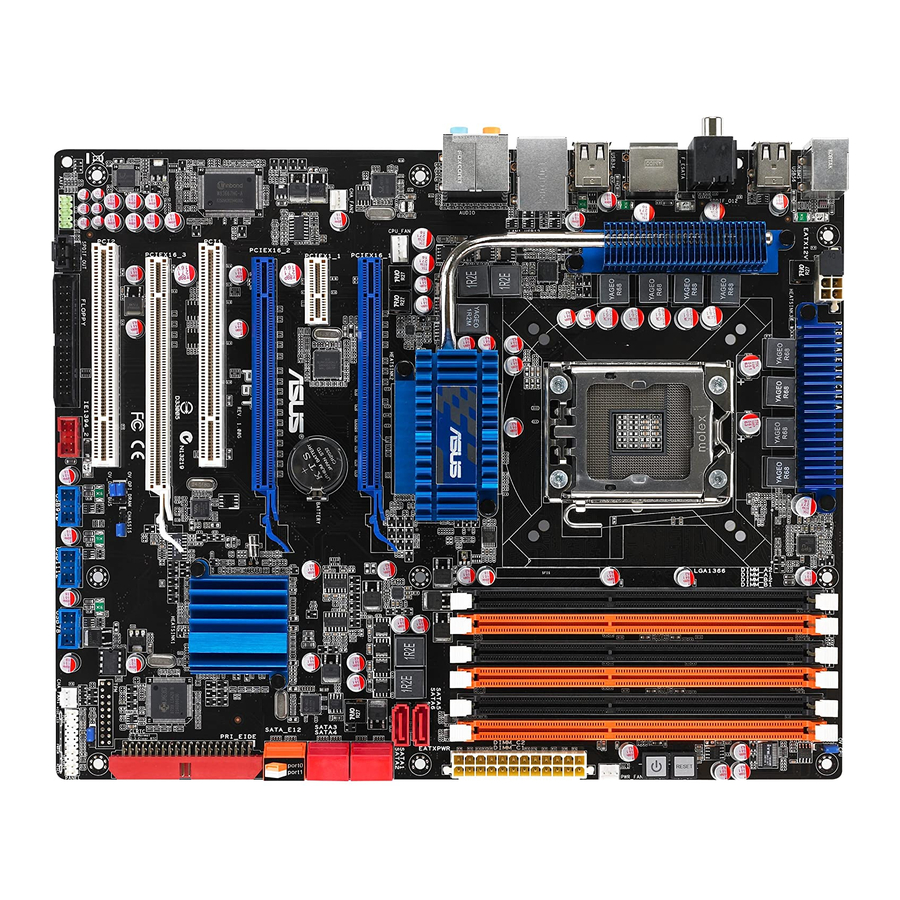
Page 26: Motherboard Overview
Motherboard overview 2.2.1 Motherboard layout Refer to 2.8 Connectors for more information about rear panel connectors and internal connectors. Chapter 2: Hardware information... -
Page 27: Layout Contents
IEEE 1394a port connector (10-1 pin IE1394_2) 2-33 Floppy disk drive connector (34-1 pin FLOPPY) 2-28 Optical drive audio connector (4-pin CD) 2-37 Front panel audio connector (10-1 pin AAFP) 2-35 Digital audio connector (4-1 pin SPDIF_OUT) 2-37 ASUS P6T... -
Page 28: Placement Direction
2.2.3 Placement direction When installing the motherboard, make sure that you place it into the chassis in the correct orientation. The edge with external ports goes to the rear part of the chassis as indicated in the image below. 2.2.4 Screw holes Place nine (9) screws into the holes indicated by circles to secure the motherboard to the chassis. -
Page 29: Central Processing Unit (Cpu)
ASUS will shoulder the cost of repair only if the damage is shipment/transit-related. • Keep the cap after installing the motherboard. ASUS will process Return Merchandise Authorization (RMA) requests only if the motherboard comes with the cap on the LGA1366 socket. -
Page 30: Installing The Cpu
2.3.1 Installing the CPU To install a CPU: Locate the CPU socket on the motherboard. Before installing the CPU, make sure that the cam box is facing towards you and the load lever is on your left. Press the load lever with your Retention tab thumb (A), then move it to the left (B) until it is released from the... - Page 31 The thermal paste is toxic and inedible. If it gets into your eyes or touches your skin, ensure to wash it off immediately and seek professional medical help. To prevent contaminating the paste, DO NOT spread the paste with your finger directly. ASUS P6T...
- Page 32 Close the load plate (A), and then push the load lever (B) until it snaps into the retention tab. Chapter 2: Hardware information...
-
Page 33: Installing The Cpu Heatsink And Fan
Push down two fasteners at a time in a diagonal sequence to secure the heatsink and fan assembly in place. Orient the heatsink and fan assembly such that the CPU fan cable is closest to the CPU fan connector. ASUS P6T... -
Page 34: Uninstalling The Cpu Heatsink And Fan
Connect the CPU fan cable to the connector on the motherboard labeled CPU_FAN. DO NOT forget to connect the CPU fan connector! Hardware monitoring errors can occur if you fail to plug this connector. 2.3.3 Uninstalling the CPU heatsink and fan To uninstall the CPU heatsink and fan: Disconnect the CPU fan cable from the connector on the motherboard. -
Page 35: System Memory
Populated Populated Populated Populated Populated Due to Intel CPU spec definition, the system will not boot if only one DIMM is installed in DIMM slot A2, B2, or C2. Follow the table above for recommended memory configuration. ASUS P6T 2-11... -
Page 36: Memory Configurations
2.4.2 Memory configurations You may install 1GB and 2GB unbuffered and non-ECC DDR3 DIMMs into the DIMM sockets. • You may install varying memory sizes in Channel A, Channel B and Channel C. The system maps the total size of the lower-sized channel for the dual-channel or triple-channel configuration. - Page 37 C1) as one set of Triple-channel memory configuration. • ASUS exclusively provides hyper DIMM support function. • Hyper DIMM support is subject to the physical characteristics of individual CPUs. • Visit the ASUS website for the latest QVL. ASUS P6T 2-13...
- Page 38 P6T Motherboard Qualified Vendors Lists (QVL) DDR3-1600MHz capability DIMM socket support (Optional) Chip Timing Vendor Part No. Size Chip NO. Voltage Brand DIMM (BIOS) CL8-8-8-24 1.65- A-DATA AD31600E001GMU Heat-Sink Package • • • • (Kit of 3) (1333-9-9-9-24) 1.85 BoxP/N: TWIN3X2048- 7-7-7-20 CORSAIR...
- Page 39 • • KINGSTON KVR1333D3N9/2G ELPIDA J1108BASE-DJ-E (1333-9-9-9-24) • • • • MT8JTF12864AY- MICRON MICRON Z9HWR (1333-9-9-9-24) • • • 1G4BYES MT16JTF25664AY- MICRON MICRON Z9HWR (1333-9-9-9-24) • • • • 1G4BYES OCZ3RPX1333EB2GK Heat-Sink Package (1066-6-5-5-20) • • • ASUS P6T 2-15...
- Page 40 P6T Motherboard Qualified Vendors Lists (QVL) DDR3-1333MHz capability (continued) DIMM socket support (Optional) Chip Timing Vendor Part No. Size Chip NO. Voltage Brand Dimm(Bios) 7-7-7 OCZ3X1333GK Heat-Sink Package • • (Kit of 3) (1066-6-6-6-16) 7-7-7-20 OCZ3P13332GK Heat-Sink Package • (1333-9-9-9-24) OCZ3P13334GK Heat-Sink Package 7 (1333-7-7-7-20)
- Page 41 Triple-channel memory configuration. • According to Intel spec definition, DDR3-1600 is supported for one DIMM per channel only. ASUS exclusively provides two DDR3-1600 DIMM support for each memory channel. • Visit the ASUS website for the latest QVL.
-
Page 42: Installing A Dimm
2.4.3 Installing a DIMM Make sure to unplug the power supply before adding or removing DIMMs or other system components. Failure to do so may cause severe damage to both the motherboard and the components. Unlock a DIMM socket by DIMM notch pressing the retaining clips outward. -
Page 43: Expansion Slots
IRQ” or that the cards do not need IRQ assignments. Otherwise, conflicts will arise between the two PCI groups, making the system unstable and the card inoperable. Refer to the table on the next page for details. ASUS P6T 2-19... -
Page 44: Interrupt Assignments
2.5.3 Interrupt assignments Standard interrupt assignments Priority Standard function System Timer Keyboard Controller – Redirect to IRQ#9 Communications Port (COM1)* IRQ Holder for PCI Steering* Floppy Disk Controller Reserved System CMOS/Real Time Clock IRQ Holder for PCI Steering* IRQ Holder for PCI Steering* IRQ Holder for PCI Steering* Reserved Numeric Data Processor... -
Page 45: Pci Slots
PCI slot 2 PCIe 2.0 x16_3 slot (white, at x4 link) PCI slot 1 PCIe 2.0 x16_2 slot (blue, at x16 link) PCI Express x1_1 slot PCIe 2.0 x16_1 slot (blue, at x16 link) ASUS P6T 2-21... - Page 46 PCI Express operating mode VGA configuration PCIe x16_1 PCIe x16_2 PCIe x16_3 x16 (Recommend Single VGA/PCIe card x16 (PCIe card) x4 (PCIe card) for single VGA) Dual VGA/PCIe card Triple VGA/PCIe card • In single VGA card mode, use first the PCIe 2.0 x16_1 slot (blue) or PCIe 2.0 x16_2 slot (blue) for a PCI Express x16 graphics card to get better performance.
-
Page 47: Jumpers
• Due to the chipset behavior, AC power off is required to enable C.P.R. function. You must turn off and on the power supply or unplug and plug the power cord before rebooting the system. ASUS P6T 2-23... - Page 48 CPU / DRAM Bus / QPI DRAM overvoltage setting (3-pin OV_CPU, 3-pin OV_DRAM_BUS, 3-pin OV_QPI_DRAM) These jumpers allow you to enable or disable the advanced CPU, DRAM Bus, and QPI DRAM overvoltage settings in BIOS. Read the following information before you change the jumper settings. OV_CPU OV_DRAM_BUS OV_QPI_DRAM...
-
Page 49: Onboard Switches
This is ideal for overclockers and gamers who continually change settings to enhance system performance. Power-on switch Press the power-on switch to wake/power up the system. Reset switch Press the reset switch to reboot the system. ASUS P6T 2-25... -
Page 50: Connectors
Connectors 2.8.1 Rear panel connectors PS/2 mouse port (green). This port is for a PS/2 mouse. Coaxial S/PDIF Out port. This port connects an external audio output device via a coaxial S/PDIF cable. IEEE 1394a port. This 6-pin IEEE 1394a port provides high-speed connectivity for audio/video devices, storage peripherals, PCs, or portable devices. - Page 51 S/PDIF cable. 15. USB 2.0 ports 5 and 6. These 4-pin Universal Serial Bus (USB) ports are available for connecting USB 2.0 devices. 16. PS/2 keyboard port (purple). This port is for a PS/2 keyboard. ASUS P6T 2-27...
-
Page 52: Internal Connectors
2.8.2 Internal connectors Floppy disk drive connector (34-1 pin FLOPPY) This connector is for the provided floppy disk drive (FDD) signal cable. Insert one end of the cable to this connector, then connect the other end to the signal connector at the back of the floppy disk drive. Pin 5 on the connector is removed to prevent incorrect cable connection when using a FDD cable with a covered Pin 5. - Page 53 Ultra DMA cable connector. This prevents incorrect insertion when you connect the IDE cable. • Use the 80-conductor IDE cable for Ultra DMA 133/100/66 IDE devices. If any device jumper is set as “Cable-Select,” make sure all other device jumpers have the same setting. ASUS P6T 2-29...
- Page 54 ICH10R Serial ATA connectors [red] (7-pin SATA 1-6) These connectors are for the Serial ATA signal cables for Serial ATA hard disk drives and optical disc drives. If you installed Serial ATA hard disk drives, you can create a RAID 0, 1, 5, and 10 configuration with the Intel Matrix Storage Technology through the ®...
- Page 55 ® SATA_E1 (orange, Port 0) NOTE: The sticker on the SATA connector illustrates the definition of SATA_E1 and SATA_E2 ports when using Drive Xpert function. Refer to 4.3.10 ASUS Drive Xpert for detailed application instructions. SATA_E2 (white, Port 1) •...
- Page 56 If your chassis suppots front panel USB ports, you can attach a front panel USB cable to these connectors. Connect the USB cable to ASUS Q-Connector (USB, blue) first, and then install the Q-Connector (USB) to the USB connector onboard.
- Page 57 Never connect a USB cable to the IEEE 1394a connector. Doing so will damage the motherboard! You can attach a FireWire/1394 cable to this connector if your chassis suppots the front panel IEEE1394 port. ASUS P6T 2-33...
- Page 58 These are not jumpers! Do not place jumper caps on the fan connectors! • Only the CPU-FAN and CHA-FAN 1–2 connectors support the ASUS Advanced Q-Fan feature. • If you install two or more VGA cards, we recommend that you plug the rear chassis fan cable to the motherboard connector labeled CHA_FAN2 for better thermal environment.
- Page 59 Front Panel Type item in the BIOS is set to [HD Audio]. If you want to connect an AC' 97 front panel audio module to this connector, set the item to [AC97]. See page 3-29 or details. ASUS P6T 2-35...
- Page 60 • If you are uncertain about the minimum power supply requirement for your system, refer to the Recommended Power Supply Wattage Calculator at http://support.asus.com/PowerSupplyCalculator/PSCalculator. aspx?SLanguage=en-us for details. • If you want to use two or more high-end PCI Express x16 cards, use a PSU with 1000 W power or above to ensure the system stability.
- Page 61 12. Digital audio connector (4-1 pin SPDIF_OUT) This connector is for an additional Sony/Philips Digital Interface (S/PDIF) port(s). If you are using ASUS HDMI-equipped graphics card, connect the HDMI card to this connector with a S/PDIF out cable. The S/PDIF out cable are purchased separately.
-
Page 62: System Panel Connector
13. System panel connector (20-8 pin PANEL) This connector supports several chassis-mounted functions. • System power LED (2-pin PLED) This 2-pin connector is for the system power LED. Connect the chassis power LED cable to this connector. The system power LED lights up when you turn on the system power, and blinks when the system is in sleep mode. - Page 63 ASUS Q-Connector (system panel) You can use the ASUS Q-Connector to connect/disconnect chassis front panel cables in a few steps. Refer to the instructions below to install the ASUS Q-Connector. Connect the front panel cables to the ASUS Q-Connector. Refer to the labels on the Q-Connector...
-
Page 64: Starting Up For The First Time
Starting up for the first time After making all the connections, replace the system case cover. Be sure that all switches are off. Connect the power cord to the power connector at the back of the system chassis. Connect the power cord to a power outlet that is equipped with a surge protector. -
Page 65: 2.10 Turning Off The Computer
BIOS setting. Pressing the power switch for more than four seconds lets the system enter the soft-off mode regardless of the BIOS setting. Refer to section 3.6 Power Menu in Chapter 3 for details. ASUS P6T 2-41... - Page 66 2-42 Chapter 2: Hardware information...
-
Page 67: Chapter 3: Bios Setup
This chapter tells how to change the system settings through the BIOS Setup menus. Detailed descriptions of the BIOS parameters are also provided. BIOS setup... - Page 68 Managing and updating your BIOS ..........3-1 BIOS setup program ..............3-9 Main menu .................. 3-12 Ai Tweaker menu ................ 3-17 Advanced menu ................. 3-25 Power menu ................3-32 Boot menu .................. 3-36 Tools menu ................. 3-40 Exit menu ..................3-45 ASUS P6T...
-
Page 69: Managing And Updating Your Bios
ASUS Update (Updates the BIOS in Windows environment.) ® ASUS EZ Flash 2 (Updates the BIOS using a floppy disk or USB flash disk.) ASUS AFUDOS (Updates the BIOS using a bootable floppy disk) ASUS CrashFree BIOS 3 (Updates the BIOS using a bootable floppy disk, USB flash disk or the motherboard support DVD when the BIOS file fails or gets corrupted.) - Page 70 To update the BIOS through the Internet: Launch the ASUS Update utility from the Windows desktop by clicking Start ® > Programs > ASUS > ASUSUpdate > ASUSUpdate. The ASUS Update main window appears. Select Update BIOS from the Select the ASUS FTP site nearest...
- Page 71 To update the BIOS through a BIOS file: Launch the ASUS Update utility from the Windows desktop by clicking Start ® > Programs > ASUS > ASUSUpdate > ASUSUpdate. The ASUS Update main window appears. Select Update BIOS from a file option from the drop-down menu, then click Next.
-
Page 72: Asus Ez Flash 2 Utility
3.1.2 ASUS EZ Flash 2 utility The ASUS EZ Flash 2 feature allows you to update the BIOS without having to go through the long process of booting from a floppy disk and using a DOS-based utility. The EZ Flash 2 utility is built-in the BIOS chip so it is accessible by pressing <Alt>... -
Page 73: Creating A Bootable Floppy Disk
Right-click Floppy Disk Drive then click Format to display the Format 3 1/2 Floppy dialog box . d. Select the Create an MS-DOS startup disk check box. e. Click Start. Copy the original or the latest motherboard BIOS file to the bootable floppy disk. ASUS P6T... -
Page 74: Afudos Utility
Updating the BIOS file To update the BIOS file using the AFUDOS utility: Visit the ASUS website (www.asus.com) and download the latest BIOS file for the motherboard. Save the BIOS file to a bootable floppy disk. Chapter 3: BIOS setup... - Page 75 Reboot the system from the hard disk drive. A:\>afudos /iP6T.ROM AMI Firmware Update Utility - Version 1.19(ASUS V2.07(03.11.24BB)) Copyright (C) 2002 American Megatrends, Inc. All rights reserved. WARNING!! Do not turn off power during flash BIOS Reading file ..done Reading flash ..done Advance Check ..Erasing flash ..done Writing flash ..done Verifying flash ..done Please restart your computer A:\> ASUS P6T...
-
Page 76: Asus Crashfree Bios 3 Utility
3.1.5 ASUS CrashFree BIOS 3 utility The ASUS CrashFree BIOS 3 is an auto recovery tool that allows you to restore the BIOS file when it fails or gets corrupted during the updating process. You can update a corrupted BIOS file using the motherboard support DVD, the floppy disk, or the USB flash disk that contains the updated BIOS file. -
Page 77: Bios Setup Program
The BIOS setup screens shown in this section are for reference purposes only, and may not exactly match what you see on your screen. • Visit the ASUS website (www.asus.com) to download the latest BIOS file for this motherboard. ASUS P6T... -
Page 78: Bios Menu Screen
3.2.1 BIOS menu screen Menu items Menu bar Configuration fields General help BIOS SETUP UTILITY Main Ai Tweaker Advanced Power Boot Tools Exit Use [ENTER], [TAB] System Time [13:51:25] or [SHIFT-TAB] to System Date [Tue 09/16/2008] select a field. Legacy Diskette A [1.44M, 3.5 in.] Language [English] Use [+] or [-] to configure the SATA1 [HDT722516DLA380] System Time. SATA2 [Not Detected] SATA3 [ATAPI DVD DH1] SATA4 [Not Detected] SATA5 [Not Detected] SATA6... -
Page 79: Menu Items
<Page Up> /<Page Down> Scroll bar keys to display the other items on the screen. 3.2.9 General help At the top right corner of the menu screen is a brief description of the selected item. ASUS P6T 3-11... -
Page 80: Main Menu
Main menu When you enter the BIOS Setup program, the Main menu screen appears, giving you an overview of the basic system information. Refer to section 3.2.1 BIOS menu screen for information on the menu screen items and how to navigate through them. BIOS SETUP UTILITY Main Ai Tweaker Advanced Power Boot Tools Exit Use [ENTER], [TAB]... -
Page 81: Sata 1-6
When set to [Disabled], the data transfer from and to the device occurs one sector at a time. Configuration options: [Disabled] [Auto] PIO Mode [Auto] Allows you to select the data transfer mode. Configuration options: [Auto] [0] [1] [2] [3] [4] ASUS P6T 3-13... -
Page 82: Storage Configuration
DMA Mode [Auto] Selects the DMA mode. Configuration options: [Auto] [SWDMA0] [SWDMA1] [SWDMA2] [MWDMA0] [MWDMA1] [MWDMA2] [UDMA0] [UDMA1] [UDMA2] [UDMA3] [UDMA4] [UDMA5] SMART Monitoring [Auto] Sets the Self-Monitoring, Analysis, and Reporting Technology. Configuration options: [Auto] [Disabled] [Enabled] 32Bit Data Transfer [Enabled] Enables or disables 32-bit data transfer. -
Page 83: Ahci Configuration
SATA Port1 [Auto] Allows you to select the type of device connected to the system. Configuration options: [Auto] [Not Installed] SMART Monitoring [Enabled] Allows you to set the Self-Monitoring, Analysis and Reporting Technology. Configration options: [Disabled] [Enabled] ASUS P6T 3-15... -
Page 84: System Information
3.3.8 System Information This menu gives you an overview of the general system specifications. The BIOS automatically detects the items in this menu. BIOS SETUP UTILITY Main Bios Information Version : 0104 Build Date : 11/11/08 Processor Type : Genuine Intel(R) CPU @ 2.67GHz Speed : 2689MHz System Memory Usable Size : 1016MB Select Screen Select Item F1 General Help F10 Save and Exit ESC Exit v02.61 (C)Copyright 1985-2008, American Megatrends, Inc. -
Page 85: Ai Tweaker Menu
Overclocks DRAM frequency by adjusting BCLK frequency. X.M.P. If you install memory module(s) supporting the eXtreme Memory Profile (X.M.P.) Technology, choose this item to set the profile(s) supported by your memory module(s) for optimizing the system performance. ASUS P6T 3-17... -
Page 86: Cpu Ratio Setting
The configuration options for the following sub-item vary depending on the DIMMs you install on the motherboard. DRAM O.C. Profile [DDR3-1805MHz] This item appears only when you set the Ai Overclock Tuner item to [D.O.C.P.] and allows you to select a DRAM O.C. profile, which applies different settings to DRAM frequency, DRAM timing and DRAM voltage. -
Page 87: Dram Frequency
DRAM REF Cycle Time [Auto] Configuration options: [Auto] [30 DRAM Clock] [36 DRAM Clock] [48 DRAM Clock] [60 DRAM Clock] [72 DRAM Clock] [82 DRAM Clock] [88 DRAM Clock] [90 DRAM Clock] [100 DRAM Clock] [110 DRAM Clock] ASUS P6T 3-19... - Page 88 DRAM WRITE Recovery Time [Auto] Configuration options: [Auto] [1 DRAM Clock] – [15 DRAM Clock] DRAM READ to PRE Time [Auto] Configuration options: [Auto] [1 DRAM Clock] – [15 DRAM Clock] DRAM FOUR ACT WIN Time [Auto] Configuration options: [Auto] [1 DRAM Clock] – [63 DRAM Clock] DRAM Back-To-Back CAS# Delay [Auto] Configuration options: [Auto] [1 DRAM Clock] –...
-
Page 89: Cpu Voltage
The value [1.90000V] of the QPI/DRAM Core Voltage item is supported only if the OV_QPI_DRAM jumper is enabled. Otherwise the maximum voltage supported is [1.70000V]. See 2. CPU / DRAM Bus / QPI DRAM overvoltage setting on page 2-24 for details. ASUS P6T 3-21... -
Page 90: Ioh Voltage
3.4.10 IOH Voltage [Auto] Allows you to set the I/O Hub (IOH) voltage. The values range from 1.10V to 1.70V with a 0.02V interval. 3.4.11 IOH PCIE Voltage [Auto] Allows you to set the IOH PCIE voltage. The values range from 1.50V to 2.76V with a 0.02V interval. -
Page 91: Dram Data Ref Voltage On Cha/B/C
Configuration options: [Auto] [700mV] [800mV] [900mV] [1000mV] 3.4.19 CPU Clock Skew [Auto] Adjusting this item may help enhancing BCLK overclocking ability. You may need to adjust the NB Clock Skew item at the same time. Configuration options: [Auto] [Normal] [Delay 100ps]–[Delay 1500ps] ASUS P6T 3-23... -
Page 92: Cpu Spread Spectrum
3.4.20 CPU Spread Spectrum [Auto] Set to [Disabled] to enhance BCLK overclocking ability or [Auto] for EMI control. Configuration options: [Auto] [Disabled] [Enabled] 3.4.21 IOH Clock Skew [Auto] Adjusting this item may help enhancing BCLK overclocking ability. You may need to adjust the CPU Clock Skew item at the same time. -
Page 93: Advanced Menu
Change Option Hardware Prefetcher [Enabled] F1 General Help Adjacent Cache Line Prefetch [Enabled] F10 Save and Exit Intel(R) Virtualization Tech [Enabled] ESC Exit CPU TM function [Enabled] v02.61 (C)Copyright 1985-2008, American Megatrends, Inc. Scroll down to display the following items: Execute-Disable Bit [Enabled] Intel(R) HT Technology [Enabled] Active Processor Cores [All] A20M [Disabled] Intel(R) SpeedStep(TM) Tech [Enabled] Intel(R) Turbo Mode tech [Enabled] Intel(R) C-STATE Tech [Disabled] v02.61 (C)Copyright 1985-2008, American Megatrends, Inc. ASUS P6T 3-25... - Page 94 CPU Ratio Setting [Auto] Allows you to adjust the ratio between CPU Core Clock and BCLK Frequency. Use the <+> and <-> keys to adjust the value. Configuration options: [Auto] [12.0] [13.0] [14.0] [15.0] [16.0] [17.0] [18.0] [19.0] [20.0] C1E Support [Enabled] Allows you to enable or disable Enhanced Halt State support.
- Page 95 This item appears only when you set the Intel(R) C-STATE Tech item to [Enabled]. We recommend that you set this item to [Auto] for BIOS to automatically detect the C-State mode supported by your CPU. Configuration options: [Auto] [C1] [C3] [C6] [C7] ASUS P6T 3-27...
-
Page 96: Chipset
3.5.2 Chipset The Chipset menu allows you to change the advanced chipset settings. Select an item then press <Enter> to display the sub-menu. BIOS SETUP UTILITY Advanced Advanced Chipset Settings Configure North Bridge features. WARMING: Setting wrong values in below sections may cause system to malfunction. Intel VT-d Configuration Intel VT-d Configuration BIOS SETUP UTILITY Advanced Intel VT-d Configuration Intel Virtualization Technology for... -
Page 97: Onboard Device Configuration
LAN Boot ROM [Disabled] This item appears only when you enable the previous item. Configuration options: [Disabled] [Enabled] Onboard 1394 Controller [Enabled] Allows you to enabled or disable the onboard IEEE 1394a controller. Configuration options: [Enabled] [Disabled] ASUS P6T 3-29... -
Page 98: Usb Configuration
3.5.4 USB Configuration The items in this menu allows you to change the USB-related features. Select an item then press <Enter> to display the configuration options. BIOS SETUP UTILITY Advanced USB Configuration Enables support for legacy USB. AUTO USB Devices Enabled: option disables 1 Mouse legacy support if no USB devices are USB Functions [Enabled] connected. USB 2.0 Controller [Enabled] USB 2.0 Controller Mode... -
Page 99: Pcipnp
When set to [NO], BIOS configures all the devices in the system. When set to [YES] and if you install a Plug and Play operating system, the operating system configures the Plug and Play devices not required for boot. Configuration options: [No] [Yes] ASUS P6T 3-31... -
Page 100: Power Menu
Power menu The Power menu items allow you to change the settings for the Advanced Power Management (APM). Select an item then press <Enter> to display the configuration options. BIOS SETUP UTILITY Main Ai Tweaker Advanced Power Boot Tools Exit Select the ACPI state Suspend Mode [Auto] used for System Repost Video on S3 Resume [No] Suspend. ACPI 2.0 Support [Disabled] ACPI APIC Support [Enabled] APM Configuration... -
Page 101: Apm Configuration
Power On By PS/2 Keyboard [Disabled] Allows you to disable the Power On by PS/2 mouse function This feature requires an ATX power supply that provides at least 1A on the +5VSB lead. Configuration options: [Disabled] [Enabled] ASUS P6T 3-33... -
Page 102: Hardware Monitor
The following item appears only when you enable the CPU Q-Fan Control item. CPU Fan Profile [Standard] Allows you to set the appropriate performance level of the ASUS Q-Fan. When set to [Standard], the CPU fan automatically adjusts depending on the CPU temperature. - Page 103 Chassis Fan Profile [Standard] Allows you to set the appropriate performance level of the ASUS Q-Fan. When set to [Standard], the chassis fan automatically adjusts depending on the chassis temperature. Set this item to [Silent] to minimize fan speed for quiet chassis fan operation, or [Turbo] to achieve maximum chassis fan speed.
-
Page 104: Boot Menu
Boot menu The Boot menu items allow you to change the system boot options. Select an item then press <Enter> to display the sub-menu. BIOS SETUP UTILITY Main Ai Tweaker Advanced Power Boot Tools Exit Specifies the Boot Boot Settings Device Priority Boot Device Priority sequence. Boot Settings Configuration A virtual floppy disk Security drive (Floppy Drive B: ) may appear when you... -
Page 105: Boot Settings Configuration
This allows you to enable or disable the full screen logo display feature. Configuration options: [Disabled] [Enabled] Set this item to [Enabled] to use the ASUS MyLogo 2 feature. AddOn ROM Display Mode [Force BIOS] Sets the display mode for option ROM. -
Page 106: Security
3.7.3 Security The Security menu items allow you to change the system security settings. Select an item then press <Enter> to display the configuration options. BIOS SETUP UTILITY Boot Security Settings <Enter> to change password. Supervisor Password : Not Installed <Enter> again to User Password : Not Installed disabled password. Change Supervisor Password Change User Password Select Screen Select Item Enter Change F1 General Help F10 Save and Exit ESC Exit v02.61 (C)Copyright 1985-2008, American Megatrends, Inc. -
Page 107: Change User Password
Password Check [Setup] When set to [Setup], BIOS checks for user password when accessing the Setup utility. When set to [Always], BIOS checks for user password both when accessing Setup and booting the system. Configuration options: [Setup] [Always] ASUS P6T 3-39... -
Page 108: Tools Menu
3.8.1 ASUS EZ Flash 2 Allows you to run ASUS EZ Flash 2. When you press <Enter>, a confirmation message appears. Use the left/right arrow key to select between [Yes] or [No], then press <Enter> to confirm your choice. Please see page 3-4, section 3.1.2 for details. -
Page 109: Express Gate
3.8.2 Express Gate [Enabled] Allows you to enable or disable the ASUS Express Gate feature. The ASUS Express Gate feature is a unique instant-on environment that provides quick access to the Internet browser and Skype. Refer to section 4.3.9 ASUS Express GATE for details. -
Page 110: Asus O.c. Profile
3.8.3 ASUS O.C. Profile This item allows you to store or load multiple BIOS settings. BIOS SETUP UTILITY Tools O.C. PROFILE Configuration Save BIOS settings O.C. Profile 1 Status : Default-Profile to Profile 1 O.C. Profile 2 Status : Default-Profile Add Your CMOS Profile. -
Page 111: Ai Net 2
ESC Exit v02.61 (C)Copyright 1985-2008, American Megatrends, Inc. Drive Xpert Group 0: Current Mode Displays the current Drive Xpert mode. The following item appears only when you change the Drive Xpert mode. Changed Mode Displays the Drive Xpert mode that you have changed. ASUS P6T 3-43... -
Page 112: Drive Xpert Mode Update
Drive Xpert Mode Update: Update To Super Speed [Press Enter] Allows you to use Super Speed function. Plug two identical SATA hard disks in the SATA_E1 (orange, port 0) and SATA_E2 (white, port 1) connectors on SATA_E2 (white, port 1) connectors on the motherboard and press <Enter>... -
Page 113: Exit Menu
Setup menus. When you select this option or if you press <F5>, a confirmation window appears. Select Ok to load default values. Select Exit & Save Changes or make other changes before saving the values to the non-volatile RAM. ASUS P6T 3-45... - Page 114 3-46 Chapter 3: BIOS setup...
-
Page 115: Chapter 4: Software Support
This chapter describes the contents of the support DVD that comes with the motherboard package and the software. Software support... - Page 116 Chapter summary Installing an operating system ........... 4-1 Support DVD information ............4-1 Software information ..............4-9 RAID configurations ..............4-47 Creating a RAID driver disk ............4-56 ASUS P6T...
-
Page 117: Installing An Operating System
The contents of the support DVD are subject to change at any time without notice. Visit the ASUS website(www.asus.com) for updates. 4.2.1 Running the support DVD Place the support DVD to the optical drive. The DVD automatically displays the Drivers menu if Autorun is enabled in your computer. -
Page 118: Drivers Menu
Installs the JMicron JMB36X controller driver. ® ASUS TurboV Installs ASUS TurboV, the advanced overclocking tool for extreme O.C. record. ASUS EPU-6 Engine Installs the ASUS EPU-6 Engine driver and utility. ASUS Express Gate Installer Allows you to install or update Express Gate functions. -
Page 119: Utilities Menu
ASUS Drive Xpert Installs the ASUS Drive Xpert utility. ASUS Update The ASUS Update utility allows you to update the motherboard BIOS in Windows ® environment. This utility requires an Internet connection either through a network or an Internet Service Provider (ISP). - Page 120 ASUS PC Probe II This smart utility monitors the fan speed, CPU temperature, and system voltages, and alerts you of any detected problems. This utility helps you keep your computer in healthy operating condition. Adobe Reader 8 Installs the Adobe Reader that allows you to open, view, and print documents in ®...
-
Page 121: Make Disk Menu
JMB36X driver disk. Intel ICH10R 32/64 bit RAID/AHCI Driver Disk Allows you to create an ICH10R 32/64bit RAID/AHCI driver disk. JMicron JMB36X 32/64bit AHCI Driver Allows you to create a JMicron JMB36X AHCI driver disk for 32/64bit system. ® ASUS P6T... -
Page 122: Manual Menu
Reader from the Utilities menu before opening a user manual ® ® file. 4.2.6 ASUS Contact information Click the Contact tab to display the ASUS contact information. You can also find this information on the inside front cover of this user guide. Chapter 4: Software support... -
Page 123: Other Information
The icons on the top right corner of the screen give additional information on the motherboard and the contents of the support DVD. Click an icon to display the specified information. Motherboard Info Displays the general specifications of the motherboard. Browse this DVD Displays the support DVD contents in graphical format. ASUS P6T... -
Page 124: Technical Support Form
Technical support Form Displays the ASUS Technical Support Request Form that you have to fill out when requesting technical support. Filelist Displays the contents of the support DVD in text format. Chapter 4: Software support... -
Page 125: Software Information
4.3.1 ASUS MyLogo 2™ The ASUS MyLogo 2™ utility lets you customize the boot logo. The boot logo is the image that appears on screen during the Power-On-Self-Tests (POST). The ASUS MyLogo2 is automatically installed when you install the ASUS Update utility from the support DVD. - Page 126 Ratio box. When the screen returns to the ASUS Update utility, flash the original BIOS to load the new boot logo. 10. After flashing the BIOS, restart the computer to display the new boot logo during POST.
-
Page 127: Asus Pc Probe Ii
® To launch the PC Probe II from the Windows desktop, click Start > All Programs > ASUS > PC Probe II > PC Probe II v1.xx.xx. The PC Probe II main window appears. ® After launching the application, the PC Probe II icon appears in the Windows taskbar. - Page 128 Button Function Opens the Configuration window Opens the Report window Opens the Desktop Management Interface window Opens the Peripheral Component Interconnect window Opens the Windows Management Instrumentation window Opens the hard disk drive, memory, CPU usage window Shows/Hides the Preference section Minimizes the application Closes the application Sensor alert...
- Page 129 Click to clicking the or buttons. You can increase also adjust the threshold values value using the Config window. Click to You cannot adjust the sensor decrease value threshold values in a small monitoring panel. ASUS P6T 4-13...
- Page 130 Monitoring sensor alert The monitor panel turns red when a component value exceeds or is lower than the threshold value. Refer to the illustrations below. Small display Large display WMI browser Click to display the WMI (Windows Management Instrumentation) browser. This ®...
- Page 131 The left panel of the tab lists all logical drives. Click a hard disk drive to display the information on the right panel. The pie chart at the bottom of the window represents the used (blue) and the available HDD space. ASUS P6T 4-15...
- Page 132 Memory usage The Memory tab shows both used and available physical memory. The pie chart at the bottom of the window represents the used (blue) and the available physical memory. Configuring PC Probe II Click to view and adjust the sensor threshold values. The Config window has two tabs: Sensor/Threshold and Preference.
-
Page 133: Asus Ai Suite
4.3.3 ASUS AI Suite ASUS AI Suite allows you to launch EPU—6 Engine, AI Nap, Fan Xpert, and TurboV utilities easily. Installing AI Suite To install AI Suite on your computer: Place the support DVD to the optical drive. The Drivers installation tab appears if your computer has an enabled Autorun feature. - Page 134 Other feature buttons Click on right corner of the main window to open the monitor window. Displays the CPU/ system temperature, CPU/memory/PCIE voltage, and CPU/ chassis fan speed Displays the FSB/CPU frequency Click on right corner of the expanded window to switch the temperature from degrees Centigrade to degrees Fahrenheit.
-
Page 135: Asus Ai Nap
4.3.4 ASUS AI Nap This feature allows you to minimize the power consumption of your computer whenever you are away. Enable this feature for minimum power consumption and a more quiet system operation. After installing AI Suite from the bundled support DVD, you can launch the utility by double-clicking the AI Suite icon on the Windows OS taskbar and click the AI Nap button on the AI Suite main window. -
Page 136: Asus Fan Xpert
4.3.5 ASUS Fan Xpert Asus Fan Xpert intelligently allows you to adjust both the CPU and chassis fan speeds according to different ambient temperatures caused by different climate conditions in different geographic regions and your PC’s system loading. The built-in variety of useful profiles offer flexible controls of fan speed to achieve a quiet and cool environment. -
Page 137: Fan Profile Modes
User: This mode allows you to change the CPU fan profile under certain limitation. For Chassis Fan, only Disable/Standard/Silent/Turbo modes could be selected. Click to close the Calibration window Click to get the calibration between the fan rotation and fan speed ratio ASUS P6T 4-21... -
Page 138: Asus Epu-6 Engine
4.3.6 ASUS EPU–6 Engine ASUS EPU–6 Engine is an energy-efficient tool that satisfies different computing needs. This utility provides four modes that you can select to enhance system performance or save power. Selecting Auto mode will have the system shift modes automatically according to current system status. -
Page 139: Engine Main Menu
Advanced settings for each mode (refer to the next page for further information) *• Click Current to show the CO2 that has been reduced since you click the Renew button *• Click Total to show the total CO2 that has been reduced since you launched 6 Engine. ASUS P6T 4-23... -
Page 140: Advanced Settings Menu
Advanced settings menu Click Setting ( ) from the 6 Engine main menu to display configuration options in each mode. Some options in certain modes are dimmed, meaning that they are not available. Click to select a mode Move the slider to adjust Click the arrow to see more... - Page 141 Never/After 3 Idle Time mins–After 5 mins–After 5 mins–After 5 mins–After 5 hours hours hours hours The values of the previous table are subject to change at any time without notice. Visit the ASUS website (www.asus.com) for updates. ASUS P6T 4-25...
-
Page 142: Asus Turbov
• For system stability, all changes made in ASUS TurboV will not be saved to BIOS settings and will not be kept on the next system boot. Use the Save Profile function to save your customized overclocking settings and manually load the profile after Windows starts. - Page 143 The value shown in CPU Ratio Mode may be higher than your CPU default setting. This is due to Intel’s Dynamic Speed Technology of automatic CPU ratio overclocking. You may turn off this feature in BIOS for manual CPU ratio adjustment. See page 3-27 for details. ASUS P6T 4-27...
-
Page 144: Audio Configurations
4.3.8 Audio configurations The Realtek audio CODEC provides 8-channel audio capability to deliver the ® ultimate audio experience on your computer. The software provides Jack-Sensing function, S/PDIF Out support, and interrupt capability. The CODEC also includes the Realtek proprietary UAJ (Universal Audio Jack) technology for all audio ports, ®... -
Page 145: Connector Settings
The Configuration options shown in this section are for reference purposes only and may not exactly match what you see on your screen. In the Windows Vista™ environment, Realtek HD Audio Manager automatically detects devices connected to the analog/digital ports and shows corresponding configuration options tabs. ASUS P6T 4-29... - Page 146 Digital Output ® The Realtek audio CODEC allows you to connect an external audio output device via the coaxial/digital S/PDIF port. You can set your listening environment, set the karaoke, or select pre-programmed equalizer settings for your listening pleasure. To set the digital output options From the Realtek HD Audio Manager, click the Digital Output tab.
- Page 147 Acoustic Echo Cancellation option button to reduce the echo from the front speakers when recording. Click the Beam Forming option button to eliminate surrounding noise interferences. Click the Default Format sub-tab for options on changing the default audio input format. Click to effect the Microphone settings and exit. ASUS P6T 4-31...
- Page 148 Realtek HD Audio Manager for Windows XP Exit button Configuration options Minimize button Control settings window Information button Information Click the information button ( ) to display information about the audio driver version, DirectX version, audio controller, audio codec, and language setting. Minimize Click the minimize button ( ) to minimize the window.
-
Page 149: Configuration Options
Line Volume, and Stereo mix, etc. by clicking the control tabs and dragging them up and down until you get the desired levels. Click the next button ( ) to display more menu options. Click to effect the Mixer settings and exit. ASUS P6T 4-33... - Page 150 Audio I/O The Audio I/O option allows you configure your input/output settings. To set the Audio I/O options From the Realtek HD Audio Manager, click the Audio I/O tab. Click the drop-down menu to select the channel configuration. The control settings window displays the status of connected devices.
- Page 151 From the Realtek HD Audio Manager, click the 3D Audio Demo tab. Click the option buttons to change the sound, moving path, or environment settings. Click to test your settings. Click to effect the 3D Audio Demo settings and exit. ASUS P6T 4-35...
-
Page 152: Asus Express Gate
4.3.9 ASUS Express Gate ASUS Express Gate is an instant-on environment that gives you quick access to the Internet, Skype, and viewing your pictures. Within a few seconds of powering on your computer, you will be at the Express Gate menu where you can start the web browser, Skype, or other Express Gate applications. -
Page 153: Using The Launchbar
Starts the Skype application, which lets you call other people on Skype for free, as well as offering affordable, high quality voice communications to phones all over the world. Opens Configuration Panel, which lets you specify network settings and other preferences. ASUS P6T 4-37... - Page 154 Opens Network settings. Opens Volume Control. Opens Input Language Settings. Opens LaunchBar Settings. Opens ASUS Utility Panel to launch the Drive Xpert function. See section 4.3.10 ASUS Drive Xpert for details. Shows “About Express Gate”. Opens Express Gate Help. Brings up Power Off window, which allows you to enter OS, restart or power off the computer.
- Page 155 DSL/cable modem is connected to your computer’s LAN port. Then enter the user name and password of your dial-up account. Click OK to enable xDSL/ cable dial-up and establish the PPPoE connection. When PPPoE is enabled, the port it uses will automatically be unchecked and grayed out. ASUS P6T 4-39...
-
Page 156: Using The Photo Manager
Shows user-created image album(s) Image control bar ASUS Express Gate supports HDDs or ODDs connected to motherboard chipset-controlled onboard SATA ports only. All onboard extended SATA ports and external SATA ports are NOT supported. 4-40 Chapter 4: Software support... -
Page 157: Updating Express Gate
Express Gate application will be released regularly, adding refinements or new applications. You can find original version of the application on the support DVD or download new versions from the ASUS support website. To update Express Gate Double-click the Express Gate setup file to start application update. -
Page 158: Repairing Express Gate
Repairing Express Gate In case Express Gate cannot start normally, you can repair Express Gate by reinstalling the application or using the repairing utility. To repair Express Gate • Click Start > All Programs > Express Gate > Express Gate Installer > Repair this application. -
Page 159: Asus Drive Xpert
4.3.10 ASUS Drive Xpert Drive Xpert, an ASUS exclusive technology, secures the data on your hard disk and enhances hard drive performance without the hassles of complicated configurations. With its user-friendly graphical user interface, you can easily arrange hard drive backups or enhance the hard drive’s transfer rate. - Page 160 Configuring EZ Backup / Super Speed EZ Backup / Super Speed might erase all original data in both hard disks. Ensure that you have back up all your data in your hard disks before using the Drive Xpert function. To start EZ Backup / Super Speed configuration: Click Drive Xpert Configuration button.
-
Page 161: Partitioning Volumes
New Partition. If the New Partition option is not available, right-click Disk item, and then select Initialize Disk to initialize the disk first. Follow the onscreen instructions to complete the volume partition. ASUS P6T 4-45... - Page 162 Click to launch the ASUS Utility Panel. Launch ASUS Utility Panel Launch Drive Xpert from the ASUS Utility Panel. • EZ Backup / Super Speed might erase all original data in both hard disks. Ensure that you have back up all your data in your hard disks before using the Drive Xpert function.
-
Page 163: Raid Configurations
RAID driver from the support DVD to a floppy disk before you install an operating system to the selected hard disk drive. Refer to section 4.5 Creating a RAID driver disk for details. ASUS P6T 4-47... -
Page 164: Installing Serial Ata Hard Disks
4.4.2 Installing Serial ATA hard disks The motherboard supports Serial ATA hard disk drives. For optimal performance, install identical drives of the same model and capacity when creating a disk array. To install the SATA hard disks for a RAID configuration: Install the SATA hard disks into the drive bays. -
Page 165: Intel Matrix Storage Manager Option Rom Utility
The navigation keys at the bottom of the screen allow you to move through the menus and select the menu options. The RAID BIOS setup screens shown in this section are for reference only and may not exactly match the items on your screen. ASUS P6T 4-49... -
Page 166: Creating A Raid 0 Set (Striped)
Creating a RAID 0 set (striped) To create a RAID 0 set: From the utility main menu, select 1. Create RAID Volume and press <Enter>. The following screen appears. Intel(R) Matrix Storage Manager option ROM v8.0.0.1027 ICH10R wRAID5 Copyright(C) 2003-08 Intel Corporation. All Rights Reserved. [ CREATE VOLUME MENU ] Name: Volume0 RAID Level: RAID0(Stripe) Disks: Select Disks Strip Size: 128KB Capacity: XXX GB Create Volume... - Page 167 Press <Enter> when the Create Volume item is highlighted. The following warning message appears. WARNING: ALL DATA ON SELECTED DISKS WILL BE LOST. Are you sure you want to create this volume? (Y/N): Press <Y> to create the RAID volume and return to the main menu, or <N> to go back to the Create Volume menu. ASUS P6T 4-51...
-
Page 168: Creating A Raid 1 Set (Mirrored)
Creating a RAID 1 set (mirrored) To create a RAID 1 set: From the utility main menu, select 1. Create RAID Volume and press <Enter>. The following screen appears. Intel(R) Matrix Storage Manager option ROM v8.0.0.1027 ICH10R wRAID5 Copyright(C) 2003-08 Intel Corporation. All Rights Reserved. [ CREATE VOLUME MENU ] Name: Volume1 RAID Level: RAID1(Mirror) Disks: Select Disks Strip Size: Capacity: XXX GB Create Volume [ HELP ]... - Page 169 We recommend a lower stripe size for server systems, and a higher stripe size for multimedia computer systems used mainly for audio and video editing. Enter the RAID volume capacity that you want and press <Enter>. The default value indicates the maximum capacity allowed. ASUS P6T 4-53...
- Page 170 Press <Enter> when the Create Volume item is highlighted. The following warning message appears. WARNING: ALL DATA ON SELECTED DISKS WILL BE LOST. Are you sure you want to create this volume? (Y/N): Press <Y> to create the RAID volume and return to the main menu or <N> to go back to the Create Volume menu. Creating a RAID 5 set (parity) To create a RAID 5 set: From the utility main menu, select 1.
- Page 171 Press <Enter> when the Create Volume item is highlighted. The following warning message appears. WARNING: ALL DATA ON SELECTED DISKS WILL BE LOST. Are you sure you want to create this volume? (Y/N): Press <Y> to create the RAID volume and return to the main menu or <N> to go back to the Create Volume menu. ASUS P6T 4-55...
-
Page 172: Creating A Raid Driver Disk
Creating a RAID driver disk A floppy disk with the RAID driver is required when installing Windows XP/Vista ® and later operating system on a hard disk drive that is included in a RAID set. For Windows Vista user, you can create a RAID driver disk with a floppy disk drive or a USB flash disk drive. - Page 173 Vista ® Insert the floppy disk/USB device with RAID driver into the floppy disk drive/ USB port. During the OS installation, select Intel(R) SATA RAID Controller (Desktop ICH10R). Follow the succeeding screen instructions to complete the installation. ASUS P6T 4-57...
- Page 174 4-58 Chapter 4: Software support...
-
Page 175: Chapter 5: Multiple Gpu Technology Support
This chapter describes how to install and configure multiple ATI CrossFireX™ and ® NVIDIA SLI™ graphics cards. Multiple GPU technology support... - Page 176 Chapter summary CrossFireX™ technology ............ 5-1 ® NVIDIA SLI™ technology ............5-6 ® ASUS P6T...
-
Page 177: Ati ® Crossfirex™ Technology
For Windows XP, go to Control Panel > Add/Remove Programs. For Windows Vista, go to Control Panel > Programs and Features. Select your current graphics card driver/s. For Windows XP, select Add/Remove. For Windows Vista, select Uninstall. Turn off your computer. ASUS P6T... -
Page 178: Installing Two Crossfirex Graphics Cards
5.1.3 Installing two CrossFireX graphics cards The following pictures are for reference only. The graphics cards and the motherboard layout may vary with models, but the installation steps remain the same. Prepare two CrossFireX-ready graphics cards. Insert the two graphics card into the PCIEX16 slots. -
Page 179: Installing Three Crossfirex Graphics Cards
Ensure that the connectors are firmly in place. Connect three independent auxiliary power sources from the power supply to the three graphics cards separately. Connect a VGA or a DVI cable to the graphics card. ASUS P6T... -
Page 180: Installing The Device Drivers
5.1.5 Installing the device drivers Refer to the documentation that came with your graphics card package to install the device drivers. • Ensure that your PCI Express graphics card driver supports the ATI ® CrossFireX™ technology. Download the latest driver from the AMD website (www.amd.com). - Page 181 From the Graphics Adapter list, select the graphics card to act as the display GPU. Select Enable CrossFireX. From the list, select the appropriate GPU combination to apply the CrossFireX technology. Click Apply, and then click OK to exit the window. ASUS P6T...
-
Page 182: Nvidia ® Sli™ Technology
NVIDIA SLI™ technology ® The motherboard supports the NVIDIA SLI™ (Scalable Link Interface) technology ® that allows you to install multi-graphics processing units (GPU) graphics cards. Follow the installation procedures in this section. 5.2.1 Requirements • In Dual SLI mode, you should have two identical SLI-ready graphics cards that are NVIDIA certified. -
Page 183: Installing Two Sli-Ready Graphics Cards
Ensure that the connector is firmly in place. Connect two independent auxiliary power sources from the power supply to the two graphics cards separately. Connect a VGA or a DVI cable to the graphics card. SLI bridge Goldfingers ASUS P6T... -
Page 184: Installing Three Sli-Ready Graphics Cards
5.2.3 Installing three SLI-ready graphics cards Prepare three SLI-ready graphics cards. Insert the three graphics card into the PCIEX16 slots. If your motherboard has more than two PCIEX16 slots, refer to Chapter 2 in this user manual for the locations of the PCIEX16 slots recommended for multi-graphics card installation. -
Page 185: Installing The Device Drivers
Right click on the empty space of the Windows ® desktop and select NVIDIA Control Panel. The NVIDIA Control Panel window appears (See Step B5 on page 5-11). B1. If you cannot see the NVIDIA Control Panel item in step (A), select Personalize. ASUS P6T... - Page 186 B2. From the Personalization window, select Display Settings. B3. From the Display Settings dialog box, click Advanced Settings. B4. Select the NVIDIA GeForce tab, and then click Start the NVIDIA Control Panel. 5-10 Chapter 5: Multiple GPU technology support...
- Page 187 Select the 3D Settings tab and enable the Show SLI Visual Indicators item. When this item is enabled, a green bar appears on the left side of the screen while 3D demonstrations are rendered, indicating the 3-way SLI status. ASUS P6T 5-11...
- Page 188 5-12 Chapter 5: Multiple GPU technology support...