Intel D945GCPE - Desktop Board Motherboard Product Manual
Desktop board
Hide thumbs
Also See for D945GCPE - Desktop Board Motherboard:
- Technical product specification (80 pages)
Table of Contents
Advertisement
Advertisement
Table of Contents

Related Manuals for Intel D945GCPE - Desktop Board Motherboard


Summary of Contents for Intel D945GCPE - Desktop Board Motherboard
- Page 1 Intel® Desktop Board D945GCPE Product Guide Order Number: D98018-001...
-
Page 2: Revision History
WARRANTIES RELATING TO FITNESS FOR A PARTICULAR PURPOSE, MERCHANTABILITY, OR INFRINGEMENT OF ANY PATENT, COPYRIGHT OR OTHER INTELLECTUAL PROPERTY RIGHT. Intel products are not intended for use in medical, life saving, or life sustaining applications. Intel may make changes to specifications and product descriptions at any time, without notice. -
Page 3: Intended Audience
The suitability of this product for other PC or embedded non-PC applications or other environments, such as medical, industrial, alarm systems, test equipment, etc., may not be supported without further evaluation by Intel. Document Organization The chapters in this Product Guide are arranged as follows:... -
Page 4: Box Contents
Intel Desktop Board D945GCPE Product Guide Terminology The table below gives descriptions of some common terms used in the product guide. Term Description Gigabyte (1,073,741,824 bytes) Gigahertz (one billion hertz) Kilobyte (1024 bytes) Megabyte (1,048,576 bytes) Mbit Megabit (1,048,576 bits) -
Page 5: Table Of Contents
Contents 1 Desktop Board Features Supported Operating Systems................10 Desktop Board Components.................11 Processor......................13 Main Memory.....................13 ® Intel 945GC Express Chipset ................14 Onboard Audio Subsystem ..................14 Input/Output (I/O) Controller ................15 LAN Subsystem ....................15 LAN Subsystem Software................15 RJ-45 LAN Connector LEDs................16 Hi-Speed USB 2.0 Support ..................16 Enhanced IDE Interface ..................17... - Page 6 Intel Desktop Board D945GCPE Product Guide Connecting the Processor Fan Heat Sink Cable..........31 Removing the Processor ................31 Installing and Removing Memory................32 Installing DIMMs ..................34 Removing DIMMs..................35 Connecting the Diskette Drive Cable ..............36 Connecting the IDE Cable..................37 Connecting the Serial ATA (SATA) Cable..............38 Connecting to Internal Headers ................39...
- Page 7 1. Feature Summary..................9 2. Desktop Board D945GCPE Components ............12 3. LAN Connector LED States ................16 4. Front Panel Audio Header Signal Names for Intel High Definition Audio....40 5. AC ’97 Audio Header Signal Names ..............40 6. Serial Port Header Signal Names..............41 7.
- Page 8 Intel Desktop Board D945GCPE Product Guide viii...
-
Page 9: Desktop Board Features
1 Desktop Board Features ® This chapter briefly describes the main features of Intel Desktop Board D945GCPE. Table 1 summarizes the major features of the desktop board. Table 1. Feature Summary microATX (218.44 millimeters [8.60 inches] x 243.84 millimeters Form Factor [9.60 inches]) -
Page 10: Supported Operating Systems
Intel Desktop Board D945GCPE Product Guide Table 1. Feature Summary (continued) LAN Support 10/100 Mb/s LAN subsystem using a Realtek RTL8101E-GR Gigabit Ethernet Controller Power • Support for Advanced Configuration and Power Interface (ACPI) Management • Suspend to RAM (STR) •... -
Page 11: Desktop Board Components
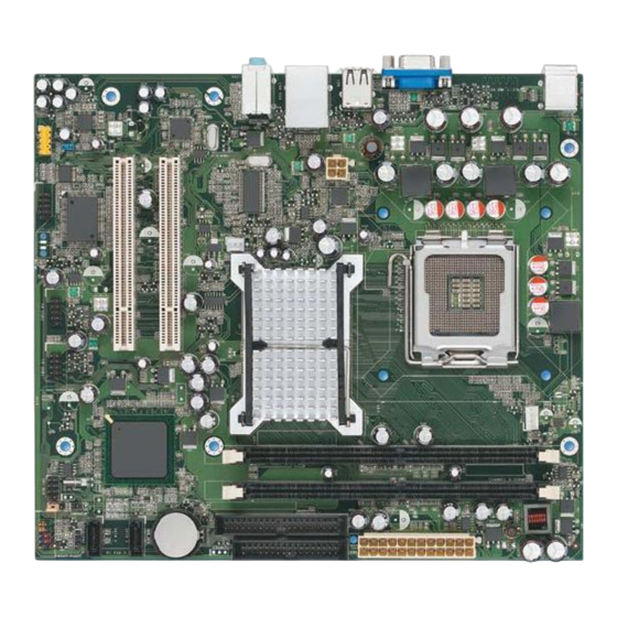
Desktop Board Features Desktop Board Components Figure 1 shows the approximate location of the major components on Desktop Board D945GCPE. Figure 1. Desktop Board D945GCPE Components... -
Page 12: Desktop Board D945Gcpe Components
Intel Desktop Board D945GCPE Product Guide Table 2. Desktop Board D945GCPE Components Label Description Front panel audio header PCI bus connector 2 PCI bus connector 1 Rear chassis fan header (3-pin) Back panel connectors 12 V processor core voltage connector (2 x 2 pin) -
Page 13: Processor
Desktop Board D945GCPE supports an Intel processor in the LGA775 package. Processors are not included with the desktop board and must be purchased separately. -
Page 14: Intel 945Gc Express Chipset
Intel Graphics Media Accelerator 950 (Intel GMA 950). The ICH7 is a centralized controller for the board’s I/O paths. Related Link: Go to the following link for more information about the Intel 945GC Express Chipset: http://www.intel.com/products/desktop/chipsets/index.htm?iid=chips_body+desk Onboard Audio Subsystem Desktop Board D945GCPE has a 4-channel (2 + 2) onboard audio subsystem that includes a Realtek ALC662 audio codec. -
Page 15: Input/Output (I/O) Controller
• Realtek RTL8101E-GR Ethernet Controller device for 10/100 Mb/s Ethernet LAN connectivity • RJ-45 connector with status indicator LEDs LAN Subsystem Software For LAN software and drivers, refer to the D945GCPE link on Intel’s World Wide Web site at: http://support.intel.com/support/motherboards/desktop... -
Page 16: Rj-45 Lan Connector Leds
Intel Desktop Board D945GCPE Product Guide RJ-45 LAN Connector LEDs Two LEDs are built into the RJ-45 LAN connector located on the back panel (see Figure 2). These LEDs indicate the status of the LAN. Figure 2. LAN Connector LEDs Table 3 describes the LED states when the board is powered up and the LAN subsystem is operating. -
Page 17: Enhanced Ide Interface
Desktop Board Features Enhanced IDE Interface The desktop board’s IDE interface handles the exchange of information between the processor and peripheral devices such as hard disk drives and CD-ROM drives. The interface supports: • Up to two IDE devices (such as hard drives) •... -
Page 18: Pci* Auto Configuration
Intel Desktop Board D945GCPE Product Guide PCI* Auto Configuration If you install a PCI add-in card in your computer, the PCI auto-configuration utility in the BIOS automatically detects and configures the resources (IRQs, DMA channels, and I/O space) for that add-in card. You do not need to run the BIOS Setup program after you install a PCI add-in card. -
Page 19: Chassis Intrusion Detection
Desktop Board Features Chassis Intrusion Detection The board supports a chassis security feature that detects if the chassis cover has been removed. The security feature uses a mechanical switch on the chassis that can be connected to the chassis intrusion header on the desktop board. See Figure 1, S on page 11 for the location of the chassis intrusion header. -
Page 20: Fan Headers
Intel Desktop Board D945GCPE Product Guide Fan Headers The function/operation of the fans is as follows: • The fans are on when the computer is in the ACPI S0 or S1 state. • The fans are off when the computer is in the ACPI S3, S4, or S5 state. -
Page 21: +5 V Standby Power Indicator
Figure 3. Standby Power Indicator Related Links: For more information on standby current requirements for the desktop board, refer to the Technical Product Specification by going to the following link, finding the product, and selecting Product Documentation from the left-hand menu: http://support.intel.com/support/motherboards/desktop/... -
Page 22: Wake From Usb
ENERGY STAR* Capable In 2007, the US Department of Energy and the US Environmental Protection Agency revised the ENERGY STAR requirements. Intel worked directly with these two governmental agencies to define the new requirements. Currently Intel Desktop Boards are capable of meeting the new ENERGY STAR requirements depending on system configuration. -
Page 23: Installing And Replacing Desktop Board Components
2 Installing and Replacing Desktop Board Components This chapter tells you how to: • Install the I/O shield • Install and remove the desktop board • Install and remove a processor • Install and remove memory • Connect the diskette drive cable •... -
Page 24: Installation Precautions
Intel Desktop Board D945GCPE Product Guide Installation Precautions When you install and test the Intel desktop board, observe all warnings and cautions in the installation instructions. To avoid injury, be careful of: • Sharp pins on connectors • Sharp pins on printed circuit assemblies •... -
Page 25: Installing The I/O Shield
Installing and Replacing Desktop Board Components Installing the I/O Shield The desktop board comes with an I/O shield. When installed in the chassis, the shield blocks radio frequency transmissions, protects internal components from dust and foreign objects, and promotes correct airflow within the chassis. Install the I/O shield before installing the desktop board in the chassis. -
Page 26: Installing And Removing The Desktop Board
Intel Desktop Board D945GCPE Product Guide Installing and Removing the Desktop Board CAUTION Only qualified technical personnel should do this procedure. Disconnect the computer from its power source before performing the procedures described here. Failure to disconnect the power before you open the computer can result in personal injury or equipment damage. -
Page 27: Installing And Removing A Processor
Installing and Replacing Desktop Board Components Installing and Removing a Processor Instructions on how to install the processor on the desktop board are given below. Installing a Processor CAUTION Before installing or removing the processor, make sure the AC power has been removed by unplugging the power cord from the computer;... -
Page 28: Lift The Load Plate
Intel Desktop Board D945GCPE Product Guide 3. Lift the load plate (Figure 7, A). Do not touch the socket contacts (Figure 7, B). Figure 7. Lift the Load Plate 4. Remove the plastic protective socket cover from the load plate (see Figure 8). Do not discard the protective socket cover. -
Page 29: Remove The Processor From The Protective Processor Cover
Installing and Replacing Desktop Board Components 5. Remove the processor from the protective processor cover. Hold the processor only at the edges, being careful not to touch the bottom of the processor (see Figure 9). Do not discard the protective processor cover. Always replace the processor cover if the processor is removed from the socket. -
Page 30: Installing The Processor Fan Heat Sink
Intel Desktop Board D945GCPE Product Guide 7. Pressing down on the load plate (Figure 11, A) close and engage the socket lever (Figure 11, B). Figure 11. Close the Load Plate Installing the Processor Fan Heat Sink Desktop Board D945GCPE has an integrated processor fan heat sink retention mechanism (RM). -
Page 31: Connecting The Processor Fan Heat Sink Cable
Processor Fan Header Removing the Processor For instructions on how to remove the processor fan heat sink and processor, refer to the processor installation manual or the Intel World Wide Web site at: Integration of the Boxed Intel Pentium 4 Processor in the 775-Land Package ®... -
Page 32: Installing And Removing Memory
Intel Desktop Board D945GCPE Product Guide Installing and Removing Memory NOTE To be fully compliant with all applicable Intel SDRAM memory specifications, the board requires DIMMs that support the Serial Presence Detect (SPD) data structure. You can access the PC Serial Presence Detect Specification at: http://www.intel.com/technology/memory/ddr/specs/dda18c32_64_128x72ag_a.pdf... -
Page 33: Use Ddr2 Dimms
Installing and Replacing Desktop Board Components To make sure you have the correct DIMM, place it on the illustration of the DDR2 DIMM in Figure 14. All the notches should match with the DDR2 DIMM. Figure 14. Use DDR2 DIMMs... -
Page 34: Installing Dimms
Intel Desktop Board D945GCPE Product Guide Installing DIMMs To install a DIMM, follow these steps: 1. Observe the precautions in "Before You Begin" on page 23. 2. Turn off all peripheral devices connected to the computer. Turn off the computer and disconnect the AC power cord. -
Page 35: Removing Dimms
Installing and Replacing Desktop Board Components Removing DIMMs To remove a DIMM, follow these steps: 1. Observe the precautions in "Before You Begin" on page 23. 2. Turn off all peripheral devices connected to the computer. Turn off the computer. 3. -
Page 36: Connecting The Diskette Drive Cable
• Observe the precautions in "Before You Begin" on page 23. • Attach the cable end labeled P1 to the diskette drive connector on the Intel Desktop Board (Figure 16, A). • Attach the cable end labeled P2 to the diskette drive (Figure 16, B). -
Page 37: Connecting The Ide Cable
• Observe the precautions in "Before You Begin" on page 23. • Attach the cable end with the single connector (blue) to the Intel desktop board (Figure 17, A). • Attach the cable end with the two closely spaced connectors (gray and black) to the drives (Figure 17, B). -
Page 38: Connecting The Serial Ata (Sata) Cable
Intel Desktop Board D945GCPE Product Guide Connecting the Serial ATA (SATA) Cable The SATA cable supports the Serial ATA protocol and connects a single drive to the desktop board. For correct cable function: 1. Observe the precautions in "Before You Begin" on page 23. -
Page 39: Connecting To Internal Headers
Installing and Replacing Desktop Board Components Connecting to Internal Headers Before connecting cables to the internal headers, observe the precautions in "Before You Begin" on page 23. Figure 19 shows the location of the internal headers. Item Description Front panel audio Serial port Chassis intrusion Alternate front panel power LED... -
Page 40: Connecting To The Front Panel Audio Header
Figure 19, A on page 39 shows the location of the front panel audio header. Table 4 shows the pin assignments for the front panel audio header. Table 4. Front Panel Audio Header Signal Names for Intel High Definition Audio... -
Page 41: Connecting To The Serial Port Header
Installing and Replacing Desktop Board Components To restore back panel audio, follow these steps: 1. Observe the precautions in "Before You Begin" on page 23. 2. Turn off all peripheral devices connected to the computer. Turn off the computer and disconnect the AC power cord. 3. -
Page 42: Connecting To The Front Panel Header
Intel Desktop Board D945GCPE Product Guide Connecting to the Front Panel Header Before connecting to the front panel header, observe the precautions in "Before You Begin" on page 23. See Figure 19, E on page 39 for the location of the front panel header. -
Page 43: Connecting To The Usb 2.0 Headers
Installing and Replacing Desktop Board Components Connecting to the USB 2.0 Headers Before connecting to the USB 2.0 headers, observe the precautions in "Before You Begin" on page 23. See Figure 19, F on page 39 for the location of the USB 2.0 headers. -
Page 44: Connecting Chassis Fan And Power Cables
Intel Desktop Board D945GCPE Product Guide Connecting Chassis Fan and Power Cables Connecting a Chassis Fan Cable Connect the chassis fan cable to the chassis fan header on the desktop board. Figure 21 shows the location of the chassis fan header. -
Page 45: Connecting Power Cables
Installing and Replacing Desktop Board Components Connecting Power Cables CAUTION Failure to use the appropriate power supply and/or not connecting the 12 V (2 x 2 pin) power connector to the desktop board may result in damage to the board or the system may not function properly. -
Page 46: Setting The Bios Configuration Jumper
Intel Desktop Board D945GCPE Product Guide Setting the BIOS Configuration Jumper NOTE Always turn off the power and unplug the power cord from the computer before moving the jumper. Moving the jumper with the power on may result in unreliable computer operation. -
Page 47: Clearing Passwords
Installing and Replacing Desktop Board Components The three-pin BIOS jumper block enables all board configuration to be done in the BIOS Setup program. Table 11 shows the jumper settings for the BIOS Setup program modes. Table 11. Jumper Settings for the BIOS Setup Program Modes Jumper Setting Mode... -
Page 48: Replacing The Battery
Intel Desktop Board D945GCPE Product Guide 8. Use the arrow keys to select Clear Passwords. Press <Enter> and Setup displays a pop-up screen requesting that you confirm clearing the password. Select Yes and press <Enter>. Setup displays the maintenance menu again. - Page 49 Installing and Replacing Desktop Board Components VIKTIGT! Risk för explosion om batteriet ersätts med felaktig batterityp. Batterier ska kasseras enligt de lokala miljövårdsbestämmelserna. VARO Räjähdysvaara, jos pariston tyyppi on väärä. Paristot on kierrätettävä, jos se on mahdollista. Käytetyt paristot on hävitettävä paikallisten ympäristömääräysten mukaisesti.
- Page 50 Intel Desktop Board D945GCPE Product Guide Προσοχή Υπάρχει κίνδυνος για έκρηξη σε περίπτωση που η μπαταρία αντικατασταθεί από μία λανθασμένου τύπου. Οι μπαταρίες θα πρέπει να ανακυκλώνονται όταν κάτι τέτοιο είναι δυνατό. Η απόρριψη των χρησιμοποιημένων μπαταριών πρέπει να γίνεται σύμφωνα με...
- Page 51 Installing and Replacing Desktop Board Components POZOR Zamenjava baterije z baterijo drugačnega tipa lahko povzroči eksplozijo. Če je mogoče, baterije reciklirajte. Rabljene baterije zavrzite v skladu z lokalnimi okoljevarstvenimi predpisi. UYARI Yanlış türde pil takıldığında patlama riski vardır. Piller mümkün olduğunda geri dönüştürülmelidir.
- Page 52 Intel Desktop Board D945GCPE Product Guide To replace the battery, follow these steps: 1. Observe the precautions in "Before You Begin" (see page 23). 2. Turn off all peripheral devices connected to the computer. Disconnect the computer’s power cord from the AC power source (wall outlet or power adapter).
-
Page 53: Updating The Bios
Updating the BIOS with the Intel Express BIOS Update Utility With the Intel Express BIOS Update utility you can update the system BIOS while in the Windows environment. The BIOS file is included in an automated update utility ® that combines the functionality of the Intel Flash Memory Update Utility and the ease-of use of Windows-based installation wizards. -
Page 54: Obtaining The Bios Update File
Intel Flash Memory Update Utility You can obtain the BIOS update file through your computer supplier or by navigating to the Desktop Board D945GCPE page on the Intel World Wide Web site at: http://support.intel.com/support/motherboards/desktop Navigate to the D945GCPE page, click “[view] Latest BIOS updates,” and select the Iflash BIOS Update utility file. -
Page 55: A Error Messages
A Error Messages Desktop Board D945GCPE reports POST errors by displaying an error message on the monitor. BIOS Error Messages When a recoverable error occurs during the POST, the BIOS displays an error message describing the problem. Table 12 gives an explanation of the BIOS error messages. Table 12. - Page 56 Intel Desktop Board D945GCPE Product Guide...
-
Page 57: B Regulatory Compliance
B Regulatory Compliance This appendix contains the following regulatory compliance information for Desktop Board D945GCPE: • Safety standards • European Union Declaration of Conformity statement • Product Ecology statements • Electromagnetic Compatibility (EMC) regulations • Product certifications Safety Standards Desktop Board D945GCPE complies with the safety standards stated in Table 13 when correctly installed in a compatible host system. -
Page 58: European Union Declaration Of Conformity Statement
Intel Desktop Board D945GCPE Product Guide European Union Declaration of Conformity Statement We, Intel Corporation, declare under our sole responsibility that the product Intel ® Desktop Board D945GCPE is in conformity with all applicable essential requirements necessary for CE marking, following the provisions of the European Council Directives 2004/108/EC (EMC Directive) and 2006/95/EC (Low Voltage Directive). -
Page 59: Product Ecology Statements
The following information is provided to address worldwide product ecology concerns and regulations. Recycling Considerations As part of its commitment to environmental responsibility, Intel has implemented the Intel Product Recycling Program to allow retail consumers of Intel’s branded products ®... - Page 60 Français Dans le cadre de son engagement pour la protection de l'environnement, Intel a mis en œuvre le programme Intel Product Recycling Program (Programme de recyclage des produits Intel) pour permettre aux consommateurs de produits Intel de recycler les produits usés en les retournant à...
-
Page 61: Lead-Free Desktop Board
Regulatory Compliance Portuguese Como parte deste compromisso com o respeito ao ambiente, a Intel implementou o Programa de Reciclagem de Produtos para que os consumidores finais possam enviar produtos Intel usados para locais selecionados, onde esses produtos são reciclados de maneira adequada. - Page 62 Intel Desktop Board D945GCPE Product Guide Table 14. Lead-Free Board Markings Description Mark Lead-Free 2 Level Interconnect: This symbol is used to identify electrical and electronic assemblies and components in which the lead (Pb) concentration level in the Intel Desktop Board substrate...
-
Page 63: Emc Regulations
Regulatory Compliance EMC Regulations Desktop Board D945GCPE complies with the EMC regulations stated in Table 15 when correctly installed in a compatible host system. Table 15. EMC Regulations Regulation Title FCC 47 CFR Part 15, Title 47 of the Code of Federal Regulations, Part 15, Subpart B, Subpart B Radio Frequency Devices. -
Page 64: Ensure Electromagnetic Compatibility (Emc) Compliance
Intel Desktop Board D945GCPE Product Guide Korean Class B statement translation: This is household equipment that is certified to comply with EMC requirements. You may use this equipment in residential environments and other non-residential environments. Ensure Electromagnetic Compatibility (EMC) Compliance... -
Page 65: Product Certifications
Description Mark UL joint US/Canada Recognized Component mark. Includes adjacent UL file number for Intel Desktop Boards: E210882. FCC Declaration of Conformity logo mark for Class B equipment. Includes Intel name and D945GCPE model designation. CE mark. Declaring compliance to European Union (EU) EMC directive and Low Voltage directive. -
Page 66: Chassis And Component Certifications
Intel Desktop Board D945GCPE Product Guide Chassis and Component Certifications Ensure that the chassis and certain components; such as the power supply, peripheral drives, wiring, and cables; are components certified for the country or market where used. Agency certification marks on the product are proof of certification. Typical...