Metrologic MS9590 VOYAGERGS series Installation And User Manual
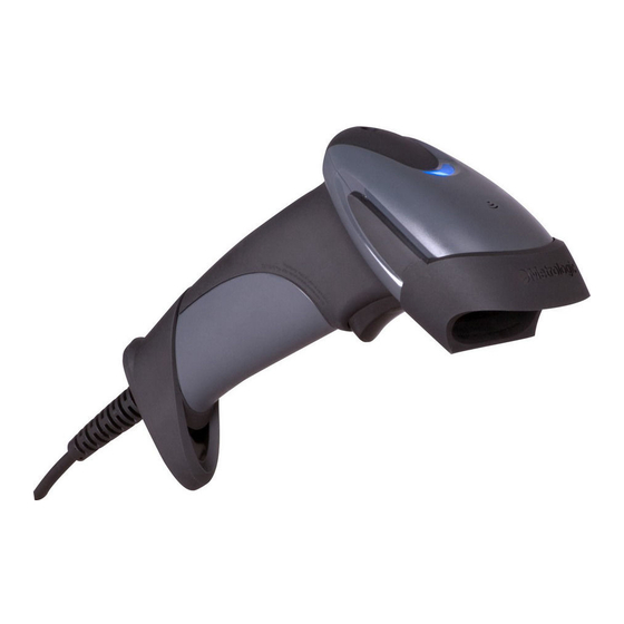
Single-line hand held laser scanner
Hide thumbs
Also See for MS9590 VOYAGERGS series:
- Installation manual (2 pages) ,
- Installation and user manual (44 pages)

Related Manuals for Metrologic MS9590 VOYAGERGS series


Summary of Contents for Metrologic MS9590 VOYAGERGS series
- Page 1 METROLOGIC INSTRUMENTS, INC. MS9590 VoyagerGS ™ Series Single-Line Hand Held Laser Scanner Installation and User's Guide...
- Page 2 Copyright © 2008 by Metrologic Instruments, Inc. All rights reserved. No part of this work may be reproduced, transmitted, or stored in any form or by any means without prior written consent, except by reviewer, who may quote brief passages in a review, or provided for in the Copyright Act of 1976.
-
Page 3: Table Of Contents
ABLE OF ONTENTS Introduction Product Overview ..................... 1 Scanner and Accessories................. 2 Scanner Components..................4 Cable Installation and Removal................ 5 Labels....................... 6 Scanner Installation RS232 (-14)...................... 7 RS485 (-106)....................8 Keyboard Wedge (-47) ..................9 Stand-Alone Keyboard (-47)................10 USB (-38 and -106) ..................11 Additional Settings for EAS Equipped Models.......... - Page 4 ABLE OF ONTENTS Configuration Modes ..................21 Upgrading the Flash ROM Firmware ..............22 Depth of Field MS9590 ......................23 MS9591 ......................24 IR Activation Range MS9590 ......................25 MS9591 ......................25 Applications and Protocols ................. 26 Troubleshooting Guide ..................27 Design Specifications Operational.....................
-
Page 5: Product Overview
NTRODUCTION Product Overview ® The MS9590 VoyagerGS™ series is part of Metrologic’s extensive Voyager branded hand-held laser scanning product family. The VoyagerGS series is the ® first Voyager product to feature trigger scanning in its design. The VoyagerGS provides an aggressive solution for scanning all standard 1D bar codes in a new ergonomic form factor that maximizes comfort and reduces fatigue. -
Page 6: Scanner And Accessories
NTRODUCTION Scanner and Accessories ASIC Part # Description MS9590 MS9590 Bar Code Scanner MS9591 MS9591 High-Density Bar Code Scanner 00-02544 MetroSelect Single-Line Configuration Guide MS9590 Series Single-Line Hand Held Laser Scanner 00-05150 Installation and User’s Guide Available for download at www.metrologic.com/corporate/download PTIONAL CCESSORIES... - Page 7 NTRODUCTION Scanner and Accessories PTIONAL CCESSORIES Part # Description Cable Compatibility Warning Use only MS9590 series compatible product cables from the list below. Damage may occur to the scanner if incompatible cables are used. Any damage incurred from incorrect cable usage will void the limited warranty shown on page 35.
-
Page 8: Scanner Components
NTRODUCTION Scanner Components No. Item Description Window Laser Aperture Trigger See How to use CodeGate on page 17 10-pin RJ45, Female Socket, Cable Connection See Scanner Pinout Connections on page 32 Speaker See Audible Indicators on page 18 White LED See Visual Indicators on page 19 Blue LED See Visual Indicators on page 19... -
Page 9: Cable Installation And Removal
NTRODUCTION Cable Installation and Removal Installation Important: If the cable is not fully latched, the unit can power intermittently. Figure 2. Connecting the Cable Plug the 10-pin RJ45 end of the cable into the 10-pin socket on the scanner. There will be an audible click when the connector lock engages. Gently pull on the cable strain relief to insure the cable is securely installed. -
Page 10: Labels
NTRODUCTION Labels Every MS9590 and MS9591 has a serial number label located on the underside of the scanner head and molded text on the scanner handle. The label and molded text provide important information such as the unit’s date of manufacture, serial number, CE and caution information. -
Page 11: Scanner Installation
CANNER NSTALLATION RS232 (-14) Turn off the host device. Plug the 10-pin RJ45 end of the PowerLink cable into the 10-pin socket on the scanner. There will be an audible click when the connector lock engages. Connect the 9-pin D-type connector of the PowerLink cable to the proper COM port on the host device. -
Page 12: Rs485 (-106)
CANNER NSTALLATION RS485 (-106) Turn off the host device. Plug the 10-pin RJ45 end of the MVC cable into the 10-pin socket on the scanner. There will be an audible click when the connector lock engages. Connect the other end of the MVC cable to the host device. -
Page 13: Keyboard Wedge (-47)
CANNER NSTALLATION Keyboard Wedge (-47) Turn off the host device. Plug the 10-pin RJ45 end of the cable into the 10-pin socket on the scanner. There will be an audible click when the connector lock engages. Disconnect the host device's keyboard. Connect the "Y"... -
Page 14: Stand-Alone Keyboard (-47)
CANNER NSTALLATION Stand-Alone Keyboard (-47) Turn off the host system. Plug the 10-pin RJ45 end of the cable into the 10-pin socket on the scanner. There will be an audible click when the connector lock engages. Plug the other end of the cable into the host's keyboard port If the scanner is receiving power from the host system, skip to step #6. -
Page 15: Usb (-38 And -106)
CANNER NSTALLATION USB (-106,-38-EAS, and -40-EAS) Turn off the host system. Plug the 10-pin RJ45 end of the USB cable into the 10-pin socket on the scanner. There will be an audible click when the connector lock engages. Plug the USB Type A end of the cable into the host's USB port. -
Page 16: Additional Settings For Eas Equipped Models
CANNER NSTALLATION Additional Settings for EAS Equipped Models All MS9590 models equipped with EAS capabilities have an EAS designation in their model numbers (example: MS9590-38-EAS). The cable supplied with these units will have additional wires for Checkpoint Device connections. Figure 10. EAS Cable Samples SW1 and SW2 are the switch banks inside the Checkpoint Device that set the deactivation range. -
Page 17: Stands
TANDS Flex Stand Components (PN 46-00709) Item Item Description Qty. Cradle Coupler Cradle Flexible Shaft Screw Cap Stand Base ¼" - 20 x ⅜" Flat Head Phillips Screw, 100° Undercut #8 Round Head Wood Screw M3 -.5 x 20 mm, Pan Head Phillips Screw M3 Flat Washer M3 Split Lock Washer Flexible Shaft Cover... -
Page 18: Assembly
TANDS Flex Stand Assembly (PN 46-00709) Figure 13. Stand Assembly... -
Page 19: Optional Fixed Mount
TANDS Optional Flex Stand Fixed Mount (PN 46-00709) In the kit, two #8 wood screws have been provided for fixed mount applications. When choosing the stand location, make sure to consider the front orientation of the stand (indicated in Figure 14). On a centerline, drill two #39 pilot holes in the countertop spaced 125 mm (4.92") apart. -
Page 20: Optional Wall/Tabletop Stand (Pn 46-00885) Optional Fixed Mount
TANDS Optional Wall/Tabletop Stand Fixed Mount (PN 46-00885 Drill two #39 pilot holes in the wall spaced 39 mm (1.54") apart on a horizontal centerline. Install one #8 wood screw in each of the pilot holes, leaving a space between the head of the screw and the wall surface. Locate the two slots marked as "A"... -
Page 21: Scanner Operation
CANNER PERATION Default Modes of Operation There are two default modes of operation available with the MS9590 series. In-Stand, Automatic Activation Mode • The laser is activated upon object detection in the IR activation area. • Bar code data is automatically decoded and transmitted. Out-of-Stand, Manual Activation Mode •... -
Page 22: Indicators Audible
NDICATORS Audible During operation, the scanner provides audible feedback that indicates the status of the scanner and latest scan. Eight settings are available for the tone of the beep (normal, 6 alternate tones and no tone). To change the beeper tone, refer to the MetroSelect Single-Line Configuration Guide or MetroSet2’s help files. -
Page 23: Visual
NDICATORS Visual Each MS9590 series scanner has three LED indicators (blue, white, and yellow) located on the head of the scanner. When the scanner is in operation, the flashing, or stationary activity of the LEDs indicates the status of the scanner and the current scan. -
Page 24: Failure Modes
NDICATORS Failure Modes One Razzberry Tone – On Power Up This indicates the scanner has experienced a flipper/motor failure. Return the scanner for repair to an authorized service center. Three Beeps – On Power Up If the scanner beeps 3 times on power up, verify the host and scanner are set to the same communication protocol. -
Page 25: Configuration Modes
ONFIGURATION ODES The MS9590 series scanners have three modes of configuration. • Bar Codes The scanner can be configured by scanning the bar codes located in the ® MetroSelect Single-Line Configuration Guide ( 00-02544). MLPN This manual can be downloaded FREE at www.metrologic.com. ®... -
Page 26: Upgrading The Flash Rom Firmware
ROM F PGRADING THE LASH IRMWARE The MS9590 and the MS9591 are part of Metrologic's line of scanners with flash upgradeable firmware. The upgrade process requires a new firmware file supplied to the customer by a customer service representative and Metrologic's MetroSet2 software . -
Page 27: Depth Of Field
EPTH OF IELD MS9590 Depth of Field Bar Code (In the Field of View) Element Width Total Start (From Scanner Face) (From Scanner Face) .127 mm 5.0 mil 83 mm (3.3") 108 mm (4.3") 25 mm (1.0") .15 mm 5.7 mil 64 mm (2.5") 127 mm (5.0") 63 mm (2.5") -
Page 28: Ms9591
EPTH OF IELD MS9591 Depth of Field Bar Code (In the Field of View) Element Width Total Start (From Scanner Face) (From Scanner Face) .10 mm 4.0 mil 25 mm (1.0") 45 mm (1.8") 20 mm (.8") .12 mm 4.8 mil 23 mm (0.9") 51 mm (2.0") 28 mm (1.1") -
Page 29: Ir Activation Range
IR A CTIVATION ANGE The MS9590 series has a built in object detection sensor that instantly turns on the scanner's laser when an object is presented within the scanner's IR activation area. Refer to the MetroSelect Single-Line Configuration Guide for information on configurable IR activation range options. -
Page 30: Applications And Protocols
PPLICATIONS AND ROTOCOLS The model number on each scanner includes the scanner number and the default communication protocol for the scanner. Version Scanner Communication Protocol(s) Identifier RS232 - TXD, RXD, RTS, CTS, DTR, DSR MS9590 Keyboard Wedge, Stand-Alone Keyboard and RS232 Transmit/Receive RS485 , USB (Bi-Directional Serial Emulation Mode, MS9591... -
Page 31: Troubleshooting Guide
ROUBLESHOOTING UIDE The following guide is for reference purposes only. Contact a Metrologic representative at 1-800-ID-Metro or 1-800-436-3876 to preserve the limited warranty terms. Symptoms Possible Causes Solution All Interfaces Check the transformer, the outlet No power is being and power strip. Make sure the supplied to the unit. - Page 32 ROUBLESHOOTING UIDE Symptoms Possible Causes Solution The bar code being Verify that the bar code being The unit powers scanned does not scanned falls into the configured up, but does not satisfy the configured criteria. scan and/or criteria for character beep.
- Page 33 ROUBLESHOOTING UIDE Symptoms Possible Causes Solution The next four items are only relevant for a Keyboard Wedge interface. Make sure that the proper PC type The unit scans AT, PS2 or XT is selected. Verify The unit’s configuration but the data is the correct country code and data is not correct.
-
Page 34: Design Specifications
ESIGN PECIFICATIONS MS9590 Series Specifications PERATIONAL Light Source: Visible Laser Diode 650 nm ± 10 nm Laser Power: 0.809 mW (peak) Pulse Duration: 560 µsec MS9590 Refer to page 23 Depth of Scan Field: MS9591 Refer to page 24 MS9590 Refer to page 23 Width of Scan Field: MS9591... -
Page 35: Mechanical
ESIGN PECIFICATIONS MS9590 Series Specifications ECHANICAL Height H 160 mm (6.30") 41 mm (1.60") Width W 65 mm (2.56") 25.4 mm (1.00") Depth: 100 mm (3.93") Weight: 150g LECTRICAL Input Voltage: 5VDC ± 0.25V Operating = 650 mW typical Power: Standby = 375 mW typical Operating = 130 mA @ 5VDC typical Current:... -
Page 36: Scanner And Cable Terminations
CANNER AND ABLE ERMINATIONS Scanner Pinout Connections The MS9590 and MS9591 scanner interfaces terminate to a 10-pin modular jack. The serial number label indicates the interface enabled when the scanner is shipped from the factory. MS9590-14 or MS9591-14 RS232 Function Ground Transmit RS232 Output Receive RS232 Input... -
Page 37: Cable Connector Configurations
CANNER AND ABLE ERMINATIONS Cable Connector Configuration (Host End) RS232 PowerLink Cable 53-53000x-3 Function Shield Ground RS232 Transmit Output RS232 Receive Input DTR Input/Light Pen Source Signal Ground Light Pen Data (DSR Out for -14 interfaces) 9-Pin Female, D-Type CTS Input RTS Output +5VDC USB Cables... - Page 38 CANNER AND ABLE ERMINATIONS Cable Connector Configuration (Host End) Keyboard Wedge Cable 53-53802x-3 Function Keyboard Clock Keyboard Data No Connect Power Ground 5-Pin DIN, Female +5 Volts DC Function PC Data No Connect Power Ground +5 Volts DC 6-Pin DIN, Male PC Clock No Connect Metrologic will supply an adapter cable with a 5-pin DIN male connector on one...
-
Page 39: Limited Warranty
CHANGES TO THE PRODUCT DESCRIBED HEREIN. (MERC) ORTH MERICA ETROLOGIC UROPEAN EPAIR ENTER Metrologic Instruments, Inc. Metrologic Eria Ibérica, SL 90 Coles Rd. C/Alfonso Gomez, 38-40, 1D Blackwood, NJ 08012-4683 28037 Madrid Customer Service Department Tel: +34 913 751 249... -
Page 40: Regulatory Compliance Safety
EGULATORY OMPLIANCE Safety ITE Equipment IEC 60950-1, EN 60950-1 Laser Laser Class 1: IEC 60825-1:1993+A1+A2, EN 60825-1:1994+A1+A2 Caution Use of controls or adjustments or performance of procedures other than those specified herein may result in hazardous laser light exposure. Under no circumstances should the customer attempt to service the laser scanner. -
Page 41: Emc
EGULATORY OMPLIANCE Emissions FCC Part 15, ICES-003, CISPR 22, EN 55022 Immunity CISPR 24, EN 55024 Note: Immunity performance is not guaranteed for scanner cables greater than 3 meters in length when fully extended. Changes or modifications not expressly approved by the party responsible for compliance could void the user’s authority to operate the equipment. -
Page 42: Class B Devices
EGULATORY OMPLIANCE Standard Europeo Attenzione Questo e’ un prodotto di classe A. Se usato in vicinanza di residenze private potrebbe causare interferenze radio che potrebbero richiedere all’utilizzatore opportune misure. Attention Ce produit est de classe “A”. Dans un environnement domestique, ce produit peut être la cause d’interférences radio. -
Page 43: Patents
ATENTS This METROLOGIC product may be covered by, but not limited to, one or more of the following US Patents: US Patent No. 4,958,984; 5,081,342; 5,260,553; 5,340,971; 5,340,973; 5,424,525; 5,468,951; 5,484,992; 5,525,789; 5,528,024; 5,591,953; 5,616,908; 5,627,359; 5,661,292; 5,777,315; 5,789,730; 5,789,731; 5,811,780; 5,825,012; 5,828,048;... -
Page 44: Index
NDEX AC ........see power failure indicator.... see indicator accessories .......2, 3 adapter ..........3 IBM ........see RS485 immunity........37 beep ......see indicator indicator blue LED......see indicator audible......18, 22, 30 failure ....20, 18–20, 27–29 visual ... 4, 19, 22, 27–29, 30 cable...... - Page 45 NDEX PowerLink......see cable termination ......32–34 protocols..... see interface tones ........... 19 troubleshooting ..... 27–29 regulatory compliance ...36–38 repair ...........35 UL ......... see caution RMA ..........35 USB ......see interface RS232 ......see interface RS485 ......see interface ventilation........31 voltage ....
- Page 47 August 2008 0 0 - 0 5 1 5 0 E...