
Related Manuals for Cub Cadet 53AH8ST3050


Summary of Contents for Cub Cadet 53AH8ST3050
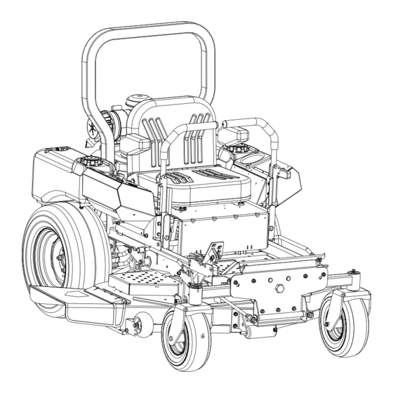
- Page 1 Hydrostatic Zero-Turn Commercial Riding Mower Professional Turf Equipment Tank Recon 48” Fabricated Deck 60” Fabricated Deck OPERATOR’S AND SERVICE MANUAL...
-
Page 2: Table Of Contents
TABLE OF CONTENTS Foreword............. . . 3 General Safety Operations . -
Page 3: Foreword
FORWARD The Tank Recon Hydrostatic Zero-Turn Commercial Riding Mower provides superb maneuver- ability, mid-mount cutting capability for professional landscapers, commercial lawn service companies, professional turf managers and golf course superintendents. The machine incor- porates many safety features that should be studied by all operators and maintenance person- nel before use. -
Page 4: General Safety Operations
GENERAL SAFETY 6. Do not check for hydraulic leaks with any part of the body. OPERATIONS 7. Do not add fuel to a machine when the engine is running and/or the exhaust system is hot. A. DANGER 8. Keep machine clean and free of debris, grass, Do not operate machine in confined areas leaves, oil, grease, etc. -
Page 5: Related To Fuel
11. When looking for oil leaks, never run your ous and is contained within the positive and negative hand over hydraulic hoses, lines or fittings. terminals as well as within the battery’s internal grid- Never tighten or adjust hydraulic hoses, lines work of plates and active materials. -
Page 6: Towing
position. Always allow other vehicles to have DANGER: the right-of-way. 12. If you hit a solid object while mowing, turn off Damaged ROPS and OPDs must be replaced prior the blade clutch switch, place the left and right to operator use! steering levers in the neutral position, move the throttle to slow, set the parking brake, shut 3. -
Page 7: G.suspension Seat
G. Suspension Seat 1. This unit is equipped with a heavy-duty vinyl fabric-covered seat incorporating adjustable armrests, an adjustable seatback, an adjust- able fore/aft track, a weight/ride adjustable mechanical suspension system, and an Operator Presence Control (OPC). 2. An OPC in the form of a switch, is integrated into the seat bottom and is connected to the machine electrical system. -
Page 8: Safety Decals
SAFETY DECALS AND LABELS WARNING SHIELD MISSING DO NOT OPERATE Part Number: 00030635 Part Number: 01002166 Part Number: 777S32801 Part Number: 777S32598 Part Number: 02005146 Part Number: 777S32797 Part Number: 02002693 Part Number: 777S30503... -
Page 9: Specifications
SPECIFICATIONS GENERAL INFO. Controls: Engine ignition and start switch; throttle; choke; left and right steering levers; electric blade clutch switch; parking brake; mower deck lift Parking Brake: Mechanical linkage brake handle to internal drum brakes Seat: Adjustable seat and armrests. 4" Adjustment (fore-aft) Frame: 2"... -
Page 10: Operating Instructions
OPERATING INSTRUCTIONS Figure. 1 Figure. 2 Engine throttle Ignition Switch Tach and Electric Blade Parking Brake Choke Lever Hour Meter Clutch Switch A.General k. Be careful when crossing gravel paths or roadways. Always turn off the blade clutch 1. When Mowing: switch and wait until the blades stop rotating a. -
Page 11: Controls
grease, grass, and leaves to reduce the b. If on an hillside, start at the bottom so that the chance of fire and permit proper cooling. turns are uphill rather than downhill. c. Align the mower so as to head directly toward Note: If low traction conditions occur, follow the object on the far side. -
Page 12: Initial Adjustments
Steering Levers Figure. 4 Fuel Shutoff Valve Foot Pedal Lift Figure. 3 direction until it stops, it will shut off the flow of fuel wheel, making the mower turn toward the side to the engine. When turned in a counterclockwise where the lever is behind. -
Page 13: Zero Turn Break-In And Operating Procedures
level. If it is below the operating range, add oil c. If the dimension at the front of the mowing through the fill tube using a funnel to bring it deck is 1/8"-1/4" (1/8” for 1-1/2”, 1/16” for 1”) up to the top of the operating range. lower than the dimension at the rear of the deck on each side of the mower, do not adjust. - Page 14 c. Become familiar with all of the machine con- g. Check safety devices: trols, instrumentation, safety and instruction 1. With the park brake engaged, try to move signs, and safety devices. one of the lap bars (speed/directional con- d. Move (or have moved) the machine to a safe, trol) from the neutral/start position —...
- Page 15 1. Make sure no bystanders, animals, or e. Push the throttle control to a position a third of objects are behind the machine. Look the way between slow and fast. behind the machine, and use extreme care. Insert the key in the ignition and start switch 2.
-
Page 16: Mower Cutting Blades
After you have mastered operating the mower, lengths of grasses are removed, and grass conditions use the second foot pedal to lower the mowing are generally dry. deck to the cutting position and pull on the electric blade clutch switch to start the blades rotating. -
Page 17: Mower Deck
Height of Cut Clevis Pin Linch Pins Figure. 7 Clean up the grass clippings and other d. Detach the mower drive belt. materials washed from underneath the e. Remove six linchpins (See Fig. 7) (4) from mower deck, and dispose of them properly. the deck and (2) from the front of the mower. -
Page 18: Hydraulic Oil
Sharpening a Blade. Using a wrench or socket rachet remove a. Set the parking brake. four hex nuts, and the four hex head cap b. Clean any debris from the blades. Keep screws. Remove the spindle assembly. blades sharp and free of build up at all times. -
Page 19: Electrical System
2. Draining Hydraulic Oil 1. Battery: The battery is located beneath the Used hydraulic oil must be disposed of properly. Do not operator’s seat. Remove the fillcaps and pour it down a drain or sewer, or dump it on open land, this check the level of the liquid electrolyte in the creates an environmental hazard. -
Page 20: Tires
5. Jump Starting are tightened. The correct adjustment occurs a. Attach the end of the red jumper cable to the when slight contact with the feeler gage Positive terminal (+) of the charged battery. occurs. Engage the BBC (PTO Clutch) a cou- b. -
Page 21: Brakes
1. Inflation Pressure: on and the lapbars are in the neutral position. If a. Traction Tires—20 psi max; 8-10 psi recom- your mower creeps, refer to Steering Lever mended Adjustment Section F4, page 23. b. Front Caster Wheel—28 psi max; 20-25 psi F. - Page 22 Note: The pumps are not owner-repairable. If a pump fails, contact your Cub Cadet Commer- cial dealer. Do not disassemble the pump. 4. Steering Lever Adjustments: The steering lever controls on this Zero Turn Mower (ZTM)
-
Page 23: H.storage
each lap bar whenever the lap bars are in their DANGER: Do not store machine inside Neutral positions. buildings or other areas where open flames sparks, or other ignition sources Note: Both lap bars must be in their Neutral are present, (such as furnaces water positions for the Park brake interlock mecha- heaters, etc). -
Page 24: Maintenance Schedule
MAINTENANCE SCHEDULE 7. Lubricate all grease fittings. Follow the Lubri- cation Chart. D. Every 100 Hour Checks A. Daily Checks 1. Change the engine oil filter. (Every 50 hours 1. Before starting engine: under heavy duty operation.) a. Check the fuel level.** 2. -
Page 25: Lubrication Chart
OIL CHART Apply a few drops of engine oil or use a spray lubricant. Apply the oil to both sides of pivot points. Wipe off any excess. Start engine and operate mower briefly to insure that oil spreads evenly. Number of Oil Points Description DAILY Deck Suspension Pivots... -
Page 26: Performance Adjustments
Performance Adjustments B. Engine RPM Check and Adjustment Description High RPM Spec. Low RPM Spec. A. High Speed Tracking Adjustment 23 & 25HP Kohler 3600 +/-50 1550 +/-100 If mower tracks to one side with both lap bars in fully NOTE: RPM Specs. -
Page 27: Deck Corner Ball Wheel Roller Settings
C. Deck Corner Ball Wheel Roller Settings Check factory settings of lap bars for the con- ditions listed above. Matching the set heights of the ball rollers on the four corners of the mower deck to the Note: If lap bar adjustments are required, desired cut height will prevent edge scalping height adjustments should be made prior to angular adjustments. -
Page 28: F Deck Leveling Procedure
F. Deck leveling Procedure raise) or counter clockwise (to lower) a few turns. Park the mower on a flat paved surface, engage Measure the blade-to-ground height at the right the parking brake, shut off the engine, remove rear blade tip. Again be sure to measure at the the key from the ignition switch, disconnect the blade tip at the rear of the right blade when spark plug wires and using the foot pedal, lower... -
Page 29: Wiring Diagram
WIRING DIAGRAM GD: 02004389... -
Page 30: Slope Gauge
SLOPE GAUGE... - Page 32 Service completed by someone other than an authorized The limited warranty set forth below is given by Cub Cadet LLC with service dealer. respect to new merchandise used for commercial and related purposes...