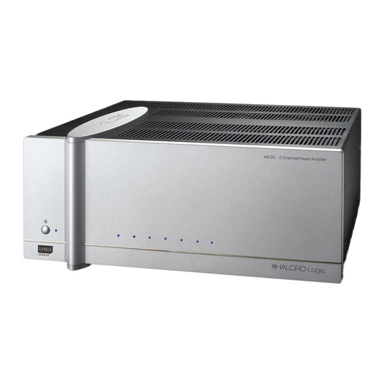
Halcro MC70 Schematic Diagram
7 channel, front & rear panels
Hide thumbs
Also See for MC70:
- Owner's manual (55 pages) ,
- Owner's manual (55 pages) ,
- Owner's manual (48 pages)
Advertisement
Quick Links
Download this manual
See also:
Owner's Manual
MC70 Front Panel
1
Standby/On button
2
Channel/Module LEDs
3
Amplifier Status Indicators
(L-R, modules 1,2,3,4,5,6,7)
MC70 Rear Panel
Manufactured
7
in Australia
Left Rear
4
Communications Card
5
RS232 Serial Connection
6
Remote Trigger Input
7
Ethernet Connection
8
Balanced Voltage Input
9
Selector Switch
MC70 front & rear panels
6
5
Left Front
Left Surround
4
3
Center
Right Surround
Right Front
10 Unbalanced Voltage Input
11
Loudspeaker Connections
12 Master On/Off Switch
13 Fus
e (F10AL 250V)
14 Mains Inlet Socket
15 Lyrus Amplification Modules (1-7)
RISK OF ELECTRIC
SHOCK
DO NOT OP EN
CAUTION
2
1
Right Rear
Advertisement


