Table of Contents
Advertisement
Quick Links
Download this manual
See also:
Owner's Manual
o o o o o o o o o o o o o o o o o o o o o o o o o o o o o o o o o o o o o o o o o o o o o o o o o o o o o o o o o o o o o o o o o o o o o o o o o
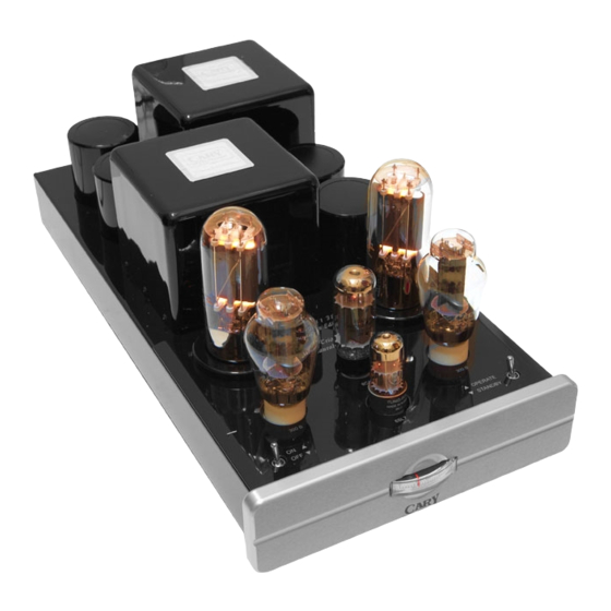
CAD 211 FE
Mono Power Amplifier
NOTE: Before installing your new component, please read this manual carefully
as it will inform you of the product specifications, proper installation and correct
operating procedures for your unit. Also included in this manual are guidelines
on how to service and care for your new Cary Audio Design product.
Advertisement
Table of Contents

Related Manuals for Cary Audio Design CAD 211 FE


Summary of Contents for Cary Audio Design CAD 211 FE
- Page 1 NOTE: Before installing your new component, please read this manual carefully as it will inform you of the product specifications, proper installation and correct operating procedures for your unit. Also included in this manual are guidelines on how to service and care for your new Cary Audio Design product.
-
Page 3: Table Of Contents
Contents ___________________________________________________________ Introduction.......................... 3 Specifications ........................4 Features..........................5 Installation ........................6-7 Operation ..........................7 Service and Care ......................... 8 Troubleshooting Guide ....................9 Diagrams ........................10-11 Warranty ..........................12... -
Page 4: Introduction
INTRODUCTION____________________________________________________ Congratulations! You have just purchased one of the most outstanding amplifiers ever made. After 17 years of continuous production we proudly announce the CAD 211 Founder’s Edition! Operating the amplifier is a simple procedure. Each unit is designed for long term stability in virtually any home operating situation. Note that if the unit is operated outside the parameters outlined in this owner’s manual, damage may result. -
Page 5: Specifications
SPECIFICATIONS ___________________________________________________ This section describes the basic specifications of the 211 FE amplifier at the time of printing. Specifications are subject to change without notice or obligation............................................POWER OUTPUT 70 Watts Class A operation, 110 watts Class AB2, up to 150 watts class B ............................................ -
Page 6: Features
FEATURES __________________________________________________________ Top Panel ............................................OFF-ON TOGGLE SWITCH Turns AC power on in the rear position The output tube will not light at this point ............................................STANDBY SWITCH Turns the filament of the output tube on in the rear position ............................................ -
Page 7: Installation
Warranty Card IN THE USA: If you are the original purchaser of a new unit from an AUTHORIZED CARY AUDIO DESIGN DEALER, please fill out the enclosed warranty registration card and return it to Cary Audio Design within 15 days of your purchase. -
Page 8: Operation
The input interconnect cables from the output of the preamplifier can be any length your installation requires. A shielded high quality interconnect cable is important to reduce chances for hum or interference. Ask your Authorized Cary Audio Design audio dealer for advice. WARNING! Page 10 shows correct tube placement positions, and 300B tube bias settings. -
Page 9: Service And Care
Non-Warranty Repairs Cary Audio Design will provide repair service for its products charging on a time and expense basis. At this time, the standard non warranty service bench fee is $125 with all parts used for repair charged extra. This may change with time and is not a quote for service. -
Page 10: Troubleshooting Guide
CAUTION Never remove or insert the AC plug when the unit is on or the AC power switch is in the “ON” position. Obstruction of the top portion of the amplifier will result in the tubes overheating. TROUBLESHOOTING GUIDE ________________________________________ SYMPTOM CAUSE REMEDY... -
Page 11: Diagrams
Diagrams ___________________________________________________________ Bias Pot Bias Jack Set the 845 tube bias to 100 mA DC Current < 845 Tubes > 6CA7 Tube ¼” bias plug 300B 300B 6SL7 Tube Standby Power The 211FE is equipped with a built in bias meter on the front of the chassis. The adjustment pot is located at the back of the chassis along with a bias jack for an external meter. - Page 12 300B Tube Pin Layout The LARGE pair of 300B tube pins should be installed toward the front of the CAD 211 FE amplifier 300B tube sockets. LOOK CAREFULLY at the tube pins to be sure that you insert them correctly. It is possible to force the tube pins into the socket the wrong way if you are not careful! If you install the tube wrong you will probably damage the amplifier and the tube.
-
Page 13: Warranty
UNITED STATES LIMITED WARRANTY Cary Audio Design warrants to the original United States purchaser for use in the United States, that Cary Audio Design vacuum tube or solid state power amplifiers, surround sound processors or preamplifiers shall be free from defects in parts or workmanship for three (3) years from the date of the original purchase. - Page 14 Cary Audio Design. Under no circumstances is Cary Audio Design liable for incidental or consequential damages. Any implied warranties imposed by law terminate one (1) year from the date of purchase.
- Page 15 CARY AUDIO DESIGN 1020 Goodworth Drive, Apex, NC 27539 phone 919-355-0010 fax 919-355-0013 www.caryaudio.com o o o o o o o o o o o o o o o o o o o o o o o o o o o o o o o o o o o o o o o o o o o o o o o o o o o o o o o o o o o o o o o o o o o o o o o o o...