
Related Manuals for Universal Audio 2-LA-2


Summary of Contents for Universal Audio 2-LA-2
- Page 1 Model 2-LA-2 Twin T4 Leveling Amplifier Universal Audio Part Number 65-00035 Universal Audio, Inc. Customer Service & Tech Support: 1-877-MY-AUDIO Business, Sales & Marketing: 1-866-UAD-1176 www.uaudio.com...
- Page 2 • IEC Power Cable • Registration Card Thank you for purchasing the Universal Audio 2-LA-2 Twin T4 Leveling Amplifier. The 2-LA-2 takes our LA-2A reproduction and updates it with modern features, modern components, and a space-saving design. The LA-2A was originally produced in the early 1960s by Teletronix, which was later acquired...
-
Page 3: A Letter From Bill Putnam, Jr
LA-2A, conveniently reconfigured into a two-channel package. Most of us at Universal Audio are musicians and/or recording engineers. We love the recording process, and we really get inspired when tracks are beautifully recorded. Our design goal for the 2-LA-2 was to build a dual/stereo compressor that we would be delighted to use ourselves—one that would capture... -
Page 4: Important Safety Instructions
Important Safety Instructions ___________________________________________________________ Before using this unit, be sure to carefully read the applicable items of these operating instructions and the safety suggestions. Afterwards, keep them handy for future reference. Take special care to follow the warnings indicated on the unit, as well as in the operating instructions. 1. -
Page 5: Table Of Contents
Table of Contents __________________________________________________________ A Letter From Bill Putnam, Jr......................... Important Safety Instructions ........................ Two Page, Two Minute Guide To Getting Started ..................Front Panel ............................Rear Panel ............................Interconnections ..........................Insider’s Secrets ..........................The Technical Stuff ..........................History of the 2-LA-2 ......................... Compressor Basics ........................ -
Page 6: Two Page, Two Minute Guide To Getting Started
It will tell you everything you need to know to get your Universal Audio 2-LA-2 up and running, without bogging you down with details. Of course, even the most expert of us has to crack a manual every once in awhile. As the saying goes, “as a last resort, read the instructions.”... - Page 7 The Two Page, Two Minute Guide To Getting Started __________________________________________________________ Step 5: Power on the 2-LA-2. The purple LED above the power switch will light up. Because the 2-LA-2 is a tube device, it needs several minutes to achieve stable operating temperature.
-
Page 8: Front Panel
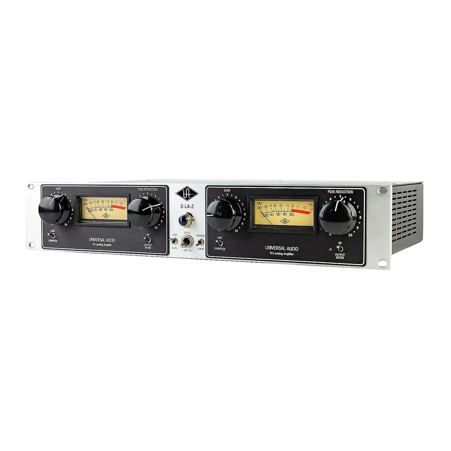
Front Panel __________________________________________________________ Figure 1: 2-LA-2 Front Panel NOTE: The 2-LA-2 provides two channels, each of which have identical front panel controls. (1) COMPRESS / LIMIT switch - Determines whether the 2-LA-2 channel is acting as a compressor or a limiter. When set to the down (COMPRESS) position, the degree of compression is gentler and at a low ratio (approximately 4:1,program-dependent). - Page 9 Front Panel __________________________________________________________ (6) Peak Reduction - Determines the amount of gain reduction provided by the 2-LA-2 channel. This control essentially combines the Threshold, Ratio, and Input controls found on other compressors. Higher settings will increase the relative amount of compression, while lower settings reduce the amount of compression (a setting of 0, with the knob at its fully counterclockwise position, results in no compression).
-
Page 10: Rear Panel
Rear Panel __________________________________________________________ Figure 2: 2-LA-2 Rear Panel (1) AC Power Connector Connect a standard, detachable IEC power cable (supplied) here. If fuse replacement is required, use only a 1.6 A time delay (slow blow) fuse for operation at 100 or 120 volts, or an 800 mA time delay (slow blow) fuse for operation at 240 volts. -
Page 11: Interconnections
Interconnections __________________________________________________________ Figure 3: Using the 2-LA-2 as a send-return processor In the above illustration, one side of the 2-LA-2 is used as a send-return processor. Typically a specialized send-return cable is used for this purpose ( see page 21 for more information) - 7 -... - Page 12 Interconnections __________________________________________________________ Figure 4: using the 2-LA-2 inline with a mic preamp In the above illustration, one side of the 2-LA-2 is used inline with a mic preamp. This is typically done to prevent peaks in the input signal from overdriving the recording device or mixer. - 8 -...
-
Page 13: Insider's Secrets
Insider’s Secrets __________________________________________________________ Whatever you can do with an LA-2A, you can do with a 2-LA-2... two times over. In addition, Link mode allows the 2-LA-2 to process not just monophonic signals, but stereo signals such as drum or backing vocal submixes. - Page 14 Insider’s Secrets __________________________________________________________ The LA-2A is also used by many engineers on kick drum. Often, a kick drum does not need a lot of compression, but a compressor can nonetheless tame the big peaks, and add some character and tone to boot.
- Page 15 Insider’s Secrets __________________________________________________________ Versatility You’ll undoubtedly find lots of other uses for your 2-LA-2. In his review, Batzdorf commented on the versatility of the LA-2A, saying, “The thing about [it] that makes it so good in the right application is the way it can control the most unruly signals “...
-
Page 16: The Technical Stuff
The Technical Stuff __________________________________________________________ History of the 2-LA-2 The original LA-2A design was the brainchild of James F. Lawrence Jr., who had been a radar operator in World War II. Following his tour of duty, Lawrence began studying electrical engineering at the University of Southern California, while also quietly designing sub-miniature telemetry devices and optical sensors for the military. - Page 17 Ocean Way and Cello Studios (now EASTWEST) in Los Angeles all preserve elements of his room designs. In 1999, Putnam’s sons Bill Jr. and James Putnam re-launched Universal Audio. One of the company’s first new products was a reissue of the LA-2A, designed to deliver complete authenticity, from its handwired components to its carefully selected tubes and original spec componentry.
-
Page 18: Compressor Basics
We here at Universal Audio, have two goals in mind: to reproduce classic analog recording equipment designed by Bill Putnam Sr. and his colleagues, and to design new recording tools in the spirit of vintage analog technology. - Page 19 The Technical Stuff __________________________________________________________ Despite the increased dynamic range, compression is especially important when recording digitally, for two reasons: One, it helps ensure that the signal is encoded at the highest possible level, where more bits are being used so that better signal definition is achieved. Secondly, it helps prevent a particularly harsh type of distortion known as clipping—something that, ironically, is especially egregious in digital recording, due to the inherent limitations of digital technology.
- Page 20 The Technical Stuff __________________________________________________________ As you can see from the illustration above, at a low ratio, a compressor has relatively less effect on the incoming signal; at higher ratios, it has more effect. When a channel is operating in compression mode (that is, when its front-panel switch is set to COMPRESS), the 2-LA-2 uses a compression ratio of approximately 4:1;...
- Page 21 The Technical Stuff __________________________________________________________ Attack and Release The main key to the sonic imprint of any compressor lies in its attack and release times; these are the parameters which most affect how “tight” or how “open” the sound will be after compression. The attack time describes the amount of time it takes the compressor circuitry to react to and reduce the gain of the incoming signal, usually given in thousandths of a second (milliseconds).
-
Page 22: Electro-Optical Compression/Limiting
(Note: While the “el-op” circuit design was one of the first of its kind, and is still used to this day in other compressor products, Universal Audio has its photo-cells uniquely manufactured to exacting specs that were originally found on the LA-2A. No other manufacturers have access to these cells.) The genius of the el-op circuit lies in its simplicity: the larger the signal that is applied to the EL panel, the brighter the light that is generated;... - Page 23 The Technical Stuff __________________________________________________________ The electroluminescent panel utilized in the T4 discharges most of its light very quickly, resulting in an extremely fast attack time (which can be as low as 10 milliseconds, depending on the frequency of the incoming signal), Even more critical to the sound of the 2-LA-2 compressor is its signal-dependent release time.
-
Page 24: Operating The 2-La-2 In Link Mode
The Technical Stuff __________________________________________________________ Operating The 2-LA-2 In Link Mode The two T4 gain reduction cells in the 2-LA-2 have been carefully matched to allow smooth and musical operation when stereo linked, with equivalent attack and release times in both channels. ... -
Page 25: Making A Custom Insert Cable
The Technical Stuff __________________________________________________________ Making A Custom Insert Cable In order to ensure unity gain, the input and output to a compressor are normally derived from a channel or bus insert send and return. Although the inputs and outputs to the 2-LA-2 use standard XLR connectors, most mixing consoles provide such inserts on unbalanced TRS (Tip/Ring/Sleeve) connectors, with the tip carrying the send and the ring carrying the return, with the sleeve serving as common ground. - Page 26 The Technical Stuff _______________________________________________________________________ 5. Your finished cable should look like the photograph below. Be sure to check continuity with a voltmeter or test light before use, to ensure proper grounding and signal flow. - 22 -...
-
Page 27: Maintenance Information
The Technical Stuff __________________________________________________________ Maintenance Information Meter Calibration The 2-LA-2 meters may occasionally need to be calibrated. This is accomplished by adjusting the GR Zero Set potentiometer, located to the left of each channel’s Meter switch. The procedure for adjusting the meter is as follows: 1. -
Page 28: Changing Fuses
The Technical Stuff _______________________________________________________________________ NOTE: When changing operating voltage, the fuse value must be changed as well. Make sure the 2-LA-2 is properly set for the voltage in your area before applying AC power to the unit! Failure to do so may damage the unit. Changing Fuses The AC power fuse is located in the AC power connector block. -
Page 29: Block Diagram
The Technical Stuff __________________________________________________________ Block Diagram As shown in the illustration above, each channel’s input transformer provides isolation and impedance matching. After this, the signal is fed into both the side-chain circuit and the gain reduction circuit. The side-chain is comprised of a voltage amplifier, a pre-emphasis filter, and a driver stage which provides the voltage necessary to drive the electro-luminescent panel. -
Page 30: Glossary Of Terms
Glossary Of Terms __________________________________________________________ Ambient noise floor - Low-level noise created by environmental factors such as fans, air conditioners, heaters, wind noise, etc. Attack time - Describes the amount of time it takes compressor circuitry to react to and reduce the gain of incoming signal. - Page 31 Glossary Of Terms __________________________________________________________ Ducking - No, nothing to do with Donald. Describes the technique of using the level of one signal to control the level of another. In broadcast applications, a music bed is often automatically “ducked” whenever the announcer’s voice is heard; it then returns to its original level when the announcer stops speaking.
- Page 32 Glossary Of Terms __________________________________________________________ Millisecond (ms) - A thousandth of a second. Patch bay - A passive, central routing station for audio signals. In most recording studios, the line-level inputs and outputs of all devices are connected to a patch bay, making it an easy matter to re-route signal with the use of patch cords.
-
Page 33: Recall Sheet
Recall Sheet __________________________________________________________ - 29 -... -
Page 34: Specifications
Specifications _______________________________________________________________________ Output Level +20 dBu nominal, @ 1% Input Level +24 dBu maximum 600 Ω balanced Output Impedance 600 Ω balanced Input Impedance Maximum Gain 35 dB +/- 1 dB Frequency Response 30 Hz to 15 kHz +0.1 dB Compressor Ratio ~4:1, soft knee, program dependent Limiter Ratio... -
Page 35: Additional Resources/Product Registration/Warranty/Service & Support
Warranty The warranty for all Universal Audio hardware is one year from date of purchase, parts and labor. Service & Support Even gear as well designed and tested as ours will sometimes fail. In those rare instances, our goal here at UA is to get you up and running again as soon as possible.