
Related Manuals for Universal Audio 1176LN


Summary of Contents for Universal Audio 1176LN
- Page 1 Model 1176LN Solid-State Limiting Amplifier Universal Audio Part Number 65-00046 Universal Audio, Inc. Customer Service & Tech Support: 1-877-MY-UAUDIO Business, Sales & Marketing: 1-866-UAD-1176 www.uaudio.com...
- Page 2 This manual provides general information, preparation for use, installation and operating instructions for the Universal Audio 1176LN. The information contained in this manual is subject to change without notice. Universal Audio, Inc. makes no warranties of any kind with regard to this manual, including, but not limited to, the implied warranties of merchantability and fitness for a particular purpose.
-
Page 3: A Letter From Bill Putnam, Jr
Most of us at Universal Audio are musicians and/or recording engineers. We love the recording process, and we really get inspired when tracks are beautifully recorded. Our design goal for the 1176LN was to build a compressor/limiter that we would be delighted to use ourselves—one that induce that “a-ha”... -
Page 4: Important Safety Instructions
Do not defeat the purpose of the grounding-type plug. 8. Cleaning - Follow these general rules when cleaning the outside of your 1176LN: a. Turn the power Off and unplug the unit b. -
Page 5: Table Of Contents
Front Panel ... Rear Panel ... Interconnections ... Insider’s Secrets ... The Technical Stuff ... History of the 1176LN ... Compressor / Limiter Basics ... About “All-Button” Mode ... About Class A ... Making A Custom Insert Cable ... Terminal Strip Connections ... -
Page 6: Two Page, Two Minute Guide To Getting Started
Getting Started With Your 1176LN: Step 1: Decide where the 1176LN is to be physically placed and place it there. The 1176LN is housed in a standard two-rackspace 19" chassis, and so we recommend that it be securely mounted in a rack if possible. - Page 7 1176 but also ensures that the meter displays the final output level. (NOTE: Depressing any Meter button other than OFF also has the effect of powering on the 1176LN; when powered on, the front panel meter lights up.) Step 5: Set the Input and Output knobs to approximately 24 (their 12 o’clock position) for unity gain.
-
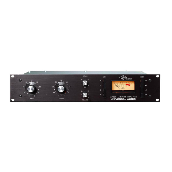
Page 8: Front Panel
Meter button and then alter the Output knob as required. ( (3) Attack - Sets the amount of time it takes the 1176LN to respond to an incoming signal and begin gain reduction. The 1176LN attack time is adjustable from 20 microseconds to 800 microseconds (both extremely fast). - Page 9 8 dB in the input signal, there will still only be a 1 dB increase in output level.) When higher ratios (12:1 or 20:1) are selected, the 1176LN is limiting instead of compressing. Note that higher Ratio settings also set the threshold higher.
- Page 10 25 for instructions for calibrating the 1176LN meter) (7) Meter Function – These four buttons power the unit on (or off) and determine what the 1176LN’s front panel VU meter displays: either the amount of gain reduction (GR), or the compressor’s output level (+8 or +4).
-
Page 11: Rear Panel
If fuse replacement is required, use only a 125 mA time delay (slow blow) fuse for operation at 115 V, or a 63 mA time delay (slow blow) fuse for operation at 230 V. Note that the 1176LN has no dedicated on-off Power button;... -
Page 12: Interconnections
Interconnections _____________________________________________________________ 1176 SA For most applications, we recommend starting with the 1176LN INPUT and OUTPUT knobs set to approximately 24 (their 12 o’clock position) for unity gain. -
Page 13: Insider's Secrets
1176s. I couldn’t part with them for anything. They sound fabulous.” Added reviewer Hugh Robjohns, writing in Sound on Sound magazine in June, 2001: “The 1176LN is judged by many to be unsurpassed as a vocal compressor, and I would certainly agree that it can be extremely effective. - Page 14 Drums In the world of recording, there’s probably no greater challenge than getting powerful and precise drum sounds. The 1176LN has long been the compressor of choice for engineers for kick drum, snare drum, and overhead or ambient mics. “I’ll always place one big mic, like a U47 (Neumann) or a ribbon mic such as a Coles or Royer, five or six feet in front of the drums,”...
- Page 15 You’ll find that you can make almost any bass sound fatter and warmer, yet still retain its definition, by running its signal through a 1176LN set to a ratio of 4:1, with fairly fast attack and release times (set both knobs to approximately 3 o’clock) and input and output at roughly unity gain (both knobs at around “24”).
- Page 16 Probably the most distorted sound you’ll get out of the 1176LN is in “All-Button” mode, with attack and release set to their fastest times. By simply backing off on the Input, Attack or Release controls, you can lessen the effect.
-
Page 17: The Technical Stuff
Revision C, released in September 1970, saw two major changes. One, the unit now sported a black faceplate instead of silver, and, two, it was now designated an 1176LN, with the “LN” standing for “low noise.” This model featured the first major modification to the 1176 circuit, designed by Brad Plunkett in an effort to reduce noise, hence the birth of the 1176LN. - Page 18 In 1999, Putnam’s sons Bill Jr. and James Putnam re-launched Universal Audio. In 2000, the company released its first product: a faithful reissue of the original 1176LN (revision D/E), which quickly garnered rave reviews, finding a home in hundreds of professional and project studios worldwide.
-
Page 19: Compressor / Limiter Basics
The Technical Stuff _____________________________________________________________ Compressor / Limiter Basics The function of a compressor is to automatically reduce the level of peaks in an audio signal so that the overall dynamic range—that is, the difference between the loudest sections and the softest ones—is reduced, or compressed, thus making it easier to hear every nuance of the music. - Page 20 0 dB will have their gain reduced, while those below 0 dB will be unaffected. In the 1176LN, the Input knob controls both the threshold and the amount of input signal being routed to the gain reduction circuitry. As it is turned up (clockwise), the overall degree of compression increases;...
- Page 21 Infinity:1), “brick wall” limiting kicks in—that is, almost any change in input, no matter how great, results in virtually no increase in output level. Note that the 1176LN has been designed so that selecting higher ratios also raises the threshold level.
-
Page 22: About "All-Button" Mode
Finally, an output control is employed to make up for the gain reduction applied by the gain reduction circuitry; on the 1176LN, this is the function of the Output knob. Makeup gain is generally set so that the compressed signal is raised to the point at which it matches the level of the unprocessed input signal (for example, if a signal is being reduced in level by approximately -6 dB, the output makeup gain should be set to +6 dB). - Page 23 Then follow these steps to assemble the cable: 1. Cut two lengths of audio cable suitable to reach from the 1176LN to the insert point on your mixer. Light gauge cable should be used in order to allow the two cables to comfortably fit inside a TRS jack.
-
Page 24: Terminal Strip Connections
METER (two terminals, polarized; the inner terminal connects to meter plus and the outer terminal to meter minus) Only one input connection (XLR or terminal strip) to the 1176LN should be made, or induced noise may result. However, so long as they are connected to devices of equal or greater impedance (i.e., most modern audio equipment), both output connections can be used for simultaneous use of the terminal strip and XLR output jacks. -
Page 25: Maintenance Information
Maintenance Information Calibrations There are no user serviceable parts inside the 1176LN. Unit calibration, as well as repair, should only be performed only by qualified service personnel. These calibration procedures are provided only for use by qualified service technicians. -
Page 26: Q" Bias
5. Slowly adjust R59 CW until the output decreases by 1.0 dB. Meter Driver Null A multimeter is needed to perform this calibration procedure: 1. Disconnect any input and output connections on the 1176LN. 2. Set your multimeter to measure DC volts. 3. Depress the Meter GR pushbutton. -
Page 27: Stereo Operation And Calibration
_____________________________________________________________ Stereo Operation and Calibration With the use of an external 1176 Stereo Adapter (1176SA), available from Universal Audio, two 1176LNs can be connected for stereo operation. When used in stereo operation, the Attack and Release controls on the two 1176LNs will interact so that changing the Attack or Release times on either device changes that of both devices. -
Page 28: Changing The Voltage Selector
Changing the Voltage Selector The 1176LN can operate at 115V or 230V. It will be factory preset for the voltage in your area; however, if it is necessary to change the voltage selector (located directly below the transformer on the rear panel), use a small slotted screwdriver to slide it to the desired operating voltage. -
Page 29: 1176Ln Circuit Details
Figure 1 - Block Diagram of the 1176LN Figure 1 shows a block diagram of the 1176LN. Signal limiting and compression is performed by the gain reduction section. Before the signal is applied to the gain reduction section, the audio signal is attenuated by the input stage. - Page 30 Figure 2 - Input Section As shown in Figure 2, the 1176LN input section is comprised of an adjustable passive attenuator followed by a transformer. The purpose of this section is to reduce the signal level so as not to overdrive the FET based gain reduction stage.
- Page 31 This is the basis of the limiting action. Note that the 1176LN is a feedback style compressor since the sidechain circuit samples the signal level after the gain reduction.
- Page 32 The output amplifier is a Darlington pair followed by a class A stage based on a 2N3053 transistor. The 1176LN output stage was essentially the same as the Universal Audio 1108 pre-amplifier. The output transformer is a custom transformer designed by Bill Putnam Sr. Aside from offering output impedance matching, the transformer forms an integral part of the feedback network used to stabilize the output stage.
- Page 33 The Technical Stuff _____________________________________________________________ As shown in Figure 5, this circuit controls the amount of compression as well as the attack and release times of the limiter. The input to this circuit is taken from the output of the preamplifier section, just before the volume control potentiometer (R23).
-
Page 34: Glossary Of Terms
A slow attack time allows transients to pass through unscathed before compression begins on the rest of the signal. The 1176LN attack time ranges from 20 to 800 microseconds. Auxiliary (Aux) send - A mixer bus output designed to combine and send multiple signals to an external processor or monitor system. - Page 35 Glossary of Terms _______________________________________________________________________ dBm - Short for “decibels as referenced to milliwatt,” dissipated in a standard load of 600 ohms. 1 dBm into 600 ohms results in 0.775 volts RMS. dBV - Short for “decibels as referenced to voltage,” without regard for impedance; thus, one volt equals one dBV.
- Page 36 Threshold - A term used to describe the level at which a compressor starts to work. Below the threshold point, the volume of a signal is unchanged; above it, the volume is reduced. In the 1176LN, threshold is determined by the setting of the Input and Ratio controls.
-
Page 37: Recall Sheet
Recall Sheet _______________________________________________________________________... -
Page 38: Specifications
Specifications _____________________________________________________________ Input Impedance Output Load Impedance Frequency Response Gain Distortion Signal-to-Noise Ratio Attack Time Release Time External Connections Stereo Interconnection Power Requirements Power Connector Fuse Dimensions Weight 600 Ω, bridged T-control (floating) 600 Ω (floating) 20 Hz to 20 kHz ± 1 dB 45 dB, ±... -
Page 39: Additional Resources / Product Registration / Warranty / Service & Support
Warranty The warranty for all Universal Audio hardware is one year from date of purchase, parts and labor. Service & Support Even gear as well designed and tested as ours will sometimes fail. In those rare instances, our goal here at UA is to get you up and running again as soon as possible.