Bryant 352MAV Service And Maintenance Procedures Manual
Deluxe 4-way multipoise 2-speed, 2-stage direct-vent condensing gas furnace series a
Hide thumbs
Also See for 352MAV:
- Installation, start-up, and operating instructions manual (52 pages) ,
- User's information manual (13 pages) ,
- User's information manual (12 pages)
Table of Contents
Advertisement
NOTE: Read the entire instruction manual before starting the
installation.
TABLE OF CONTENTS
SAFETY CONSIDERATIONS .....................................................1
INTRODUCTION ..........................................................................2
CARE AND MAINTENANCE.....................................................2
Cleaning and/or Replacing Air Filter.......................................3
Blower Motor and Wheel Maintenance...................................3
Cleaning Burners ......................................................................4
Cleaning Heat Exchangers........................................................5
Flushing Collector Box and Drainage System ........................7
Servicing Hot Surface Ignitor ..................................................7
Electrical Controls and Wiring.................................................8
Checking Heat Tape Operation (If Applicable) ......................8
Winterizing................................................................................9
WIRING DIAGRAM.....................................................................9
TROUBLESHOOTING .................................................................9
Status Codes..............................................................................9
Component Test ........................................................................9
SAFETY CONSIDERATIONS
Installing and servicing heating equipment can be hazardous due to
gas and electrical components. Only trained and qualified
personnel should install, repair, or service heating equipment.
Untrained personnel can perform basic maintenance functions
such as cleaning and replacing air filters. All other operations
must be performed by trained service personnel. When working on
heating equipment, observe precautions in the literature, on tags,
and on labels attached to or shipped with the unit and other safety
precautions that may apply.
Follow all safety codes. In the United States, follow all safety
codes including the National Fuel Gas Code (NFGC) NFPA
54-1999/ANSI Z223.1-1999 and the Installation Standards, Warm
Air Heating and Air Conditioning Systems (NFPA 90B)
ANSI/NFPA 90B. In Canada, refer to the CAN/CGA-B/49.1- and
service and
maintenance procedures
DELUXE 4-WAY MULTIPOISE
2-SPEED, 2-STAGE DIRECT-VENT
CONDENSING GAS FURNACE
A93040
-1-
Cancels: New
REGISTERED QUALITY SYSTEM
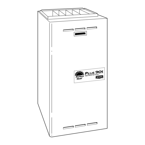
Fig. 1-Multipoise Furnace in Upflow Orientation
.2-M00 National Standard of Canada, Natural Gas and Propane
Installation Codes (NSCNGPIC). Wear safety glasses and work
gloves. Have a fire extinguisher available during start-up and
adjustment procedures and service calls.
352MAV
Series A
SP05-48
3-01
EFFICIENCY
RATING
CERTIFIED
CERTIFIED
®
Fu rna ce
icie nt Ga s
Hig hly Eff
A01060
Advertisement
Table of Contents
Troubleshooting

Related Manuals for Bryant 352MAV


Summary of Contents for Bryant 352MAV
-
Page 1: Table Of Contents
service and 352MAV maintenance procedures Series A DELUXE 4-WAY MULTIPOISE 2-SPEED, 2-STAGE DIRECT-VENT CONDENSING GAS FURNACE Cancels: New SP05-48 3-01 NOTE: Read the entire instruction manual before starting the EFFICIENCY installation. RATING CERTIFIED CERTIFIED ® REGISTERED QUALITY SYSTEM A93040 TABLE OF CONTENTS SAFETY CONSIDERATIONS .............1 INTRODUCTION ................2 ELECTROSTATIC DISCHARGE (ESD) PRECAUTIONS..2... -
Page 2: Introduction
This is the safety-alert symbol . When you see this symbol on AIRFLOW the furnace and in instructions or manuals, be alert to the potential for personal injury. Understand the signal words DANGER, WARNING, and CAU- TION. These words are used with the safety-alert symbol. DAN- GER identifies the most serious hazards which will result in severe UPFLOW personal injury or death. -
Page 3: Cleaning And/Or Replacing Air Filter
WASHABLE FILTER IN FURNACE FILTER RETAINER WASHABLE FILTER FILTER SUPPORT FILTER RETAINER WASHABLE FILTER OR DISPOSABLE MEDIA WASHABLE FILTER OR FILTER IN FILTER CABINET DISPOSABLE MEDIA FILTER IN FILTER CABINET A00233 Fig. 4—Filter Installed for Side Inlet A00232 Fig. 3—Bottom Filter Arrangement 4. -
Page 4: Cleaning Burners
8. If greasy residue is present on blower wheel, remove wheel 13. Reconnect wires. from the blower housing and wash it with an appropriate Refer to furnace wiring diagram and connect thermostat leads if degreaser. To remove wheel: previously disconnected. (See Fig. 15.) a. -
Page 5: Cleaning Heat Exchangers
8. Remove manifold, orifices, and gas valve as 1 assembly. PRIMARY HX INLET OPENINGS 9. Remove screws attaching burner assembly in burner box. 10. Remove burner assembly from burner box. NOTE: All burners are attached to burner bracket and can be removed as 1 assembly. - Page 6 TUBE ROUTING Furnace is shipped from factory in upflow configuration. Pressure tube and drain tube routing MUST match the diagrams below. Tube location when used in UPFLOW application Condensate Trap on LEFT Condensate Trap; Factory Installed Side Optional in Blower Shelf BURNER ENCLOSURE (Blower access panel removed) BURNER ENCLOSURE...
-
Page 7: Flushing Collector Box And Drainage System
B. Secondary Heat Exchangers NOTE: The condensing side (inside) of the secondary heat exchangers CANNOT be serviced or inspected. A small number of bottom outlet openings can be inspected by removing the inducer assembly. See Flushing Collector Box and Drainage System section for details on removing inducer assembly. -
Page 8: Electrical Controls And Wiring
FIELD 24-V WIRING FIELD 115-, 208/230-, 460-V WIRING FACTORY 24-V WIRING FACTORY 115-, 208/230-, 460-V WIRING NOTE 5 THERMOSTAT FIVE TERMINALS FIELD-SUPPLIED WIRE DISCONNECT THREE-WIRE HEATING 208/230- OR ONLY 460-V THREE PHASE W/W1 115-V NOTE SINGLE PHASE 208/230-V SINGLE AUXILIARY PHASE 115-V J-BOX... -
Page 9: Winterizing
NOTE: Heat tape, when used, should be wrapped around the CAUTION: Do not use ethylene glycol (Prestone II condensate drain trap and drain line. There is no need to use heat antifreeze/coolant or equivalent automotive type). Failure tape within the furnace casing. Most heat tapes are temperature of plastic components will occur. - Page 10 A99118 Fig. 13—Inducer Housing Drain Tube A99119 Fig. 14—Funnel in Drain and Antifreeze Running Through Trap 1. The inducer will start and run on high speed. 5. The blower motor operates on HI GAS-HEAT speed for 7 sec. 2. After 7 sec the inducer motor will continue to run while the hot surface ignitor HSI is energized for 15 sec, then 6.
- Page 11 CONNECTION DIAGRAM SCHEMATIC DIAGRAM (NATURAL GAS & PROPANE) TO 115VAC FIELD DISCONNECT SWITCH NOTE #1 EQUIPMENT GROUND BHI / LOR LO-GAS-HEAT MED LO NOTE #6 BHT / CLR BLWM HI-GAS-HEAT GRN / YEL GRN/YEL NOTE #14 LGPS CAP-2 BLWR SPARE SPARE HI-COOL MED HI...
- Page 12 SERVICE If status code recall is needed, do not remove power or blower door. Briefly remove and then reconnect one main limit wire to display stored status code. LED CODE ST A TUS CONTINUOUS OFF - Check for 115VAC at L1 and L2, and 24VAC at SEC1 and SEC2 . CONTINUOUS ON - Control has 24VAC power.
-
Page 13: Troubleshooting
TROUBLESHOOTING NOTES: WARNING Refer to information label on blower compartment door GUIDE for procedure for use of LED status codes and problem solving suggestions. LED indicator is viewed through window on blower ELECTRICAL SHOCK HAZARD compartment door. If 115-vac power is energized or interrupted during a ONLY QUALIFIED AND TRAINED call for heat, the indoor blower will run for 90 sec before SERVICE PERSONNEL SHOULD... - Page 14 —14—...
- Page 15 —15—...
- Page 16 © 2001 Bryant Heating & Cooling Systems 7310 W. Morris St. Indianapolis, IN 46231 —16— Printed in U.S.A. sp0548 Catalog No. 5335-201...