HP BL260c - ProLiant - G5 Troubleshooting Manual
Bladesystem c-class enclosure
Hide thumbs
Also See for BL260c - ProLiant - G5:
- User manual (96 pages) ,
- Reference manual (138 pages) ,
- Implementation manual (26 pages)

Related Manuals for HP BL260c - ProLiant - G5


Summary of Contents for HP BL260c - ProLiant - G5
-
Page 1: Troubleshooting Guide
HP BladeSystem c-Class Enclosure Troubleshooting Guide Part Number 460224-002 July 2009 (Second Edition) - Page 2 © Copyright 2007, 2009 Hewlett-Packard Development Company, L.P. The information contained herein is subject to change without notice. The only warranties for HP products and services are set forth in the express warranty statements accompanying such products and services. Nothing herein should be construed as constituting an additional warranty. HP shall not be liable for technical or editorial errors or omissions contained herein.
-
Page 3: Table Of Contents
Contents Getting started..........................5 How to use this guide ..........................5 Troubleshooting overview ........................... 6 Diagnosing the enclosure ........................... 6 Diagnosing the overall system health....................7 Diagnosing the component health...................... 7 Navigating the Insight Display ........................7 Health Summary screen..........................8 Important safety information........................ - Page 4 Procedures: Midplane assembly replacement ....................69 Component identification ......................72 HP BladeSystem c7000 Enclosure components.................... 72 Enclosure front components......................72 Enclosure rear components ......................77 HP BladeSystem c3000 Enclosure components.................... 81 Enclosure front components......................81 Enclosure rear components ......................85 Software tools and solutions......................
-
Page 5: Getting Started
Getting started How to use this guide This guide provides procedures and solutions for troubleshooting an HP BladeSystem c-Class enclosure, from using the Insight Display to more complex component-level troubleshooting. Always begin the troubleshooting process by using the Insight Display Health Summary screen to resolve all reported errors. -
Page 6: Troubleshooting Overview
Troubleshooting overview Diagnosing the enclosure When troubleshooting an enclosure, be sure that the enclosure and all components are installed properly. For more information, see the HP BladeSystem c-Class Solution Overview on the HP website (http://www.hp.com/go/bladesystem/documentation). When the system is powered on and the Insight Display is operating properly, use the Insight Display for diagnosing and troubleshooting. -
Page 7: Diagnosing The Overall System Health
Diagnosing the overall system health Background color Description Green System health is good. Amber System health is degraded. Blue Enclosure UID is active. Enclosure UID overrides the green and amber background colors. Use the Insight Display main menu to turn the enclosure UID on and off. -
Page 8: Health Summary Screen
The Main Menu appears: The Main Menu of the Insight Display has the following menu options: • Health Summary • Enclosure Settings • Enclosure Info • Blade or Port Info • Turn Enclosure UID on/off • View User Note • Chat Mode •... - Page 9 Errors are placed in the following error categories: • Device errors include device failures, degraded devices, or information messages about a component. • Location errors include missing components or components installed in the wrong bay. • Configuration errors include problems with server blades and the corresponding interconnect modules.
-
Page 10: Important Safety Information
The error category is displayed at the top of the summary screen. To view additional information for each error in the category, use the arrow keys on the Insight Display to select Details. To view the details for other errors in this category, select Next or Prev, and then press the OK button to scroll through all errors. The type and number of errors are displayed at the top of the error screen. -
Page 11: Warnings And Cautions
This symbol indicates the presence of hazardous energy circuits or electric shock hazards. Refer all servicing to qualified personnel. WARNING: To reduce the risk of injury from electric shock hazards, do not open this enclosure. Refer all maintenance, upgrades, and servicing to qualified personnel. This symbol indicates the presence of electric shock hazards. -
Page 12: Electrostatic Discharge
WARNING: To reduce the risk of personal injury or damage to the equipment, be sure that: The leveling feet are extended to the floor. • • The full weight of the rack rests on the leveling feet. The stabilizing feet are attached to the rack if it is a single-rack installation. •... -
Page 13: Grounding Methods To Prevent Electrostatic Discharge
• Keep electrostatic-sensitive parts in their containers until they arrive at static-free workstations. • Place parts on a grounded surface before removing them from their containers. • Avoid touching pins, leads, or circuitry. • Always be properly grounded when touching a static-sensitive component or assembly. Grounding methods to prevent electrostatic discharge Several methods are used for grounding. -
Page 14: Common Problem Resolution
Common problem resolution Troubleshooting with the HP BladeSystem Insight Display Always begin troubleshooting the enclosure by using the Insight Display as follows: Check the Insight Display screen. If the Insight Display background color is green, then the enclosure is operating normally and has no errors. -
Page 15: Firmware Updates
Firmware updates Download firmware updates from the following locations: • HP BladeSystem c-Class Firmware and Upgrades compatibility matrix on the HP website (http://h18004.www1.hp.com/products/blades/components/c-class-compmatrix.html) • The HP Smart Components available on the HP ProLiant Firmware Maintenance CD and the HP Support website (http://www.hp.com/support) •... -
Page 16: Hp Bladesystem Insight Display Troubleshooting
HP BladeSystem Insight Display troubleshooting Insight Display overview The Insight Display enables the rack technician to configure the enclosure initially. It also provides information about the health and operation of the enclosure. See the HP BladeSystem Onboard Administrator User Guide for additional information. The Insight Display background color varies with the condition of the enclosure health: •... -
Page 17: Symptoms: Hp Bladesystem C3000 Enclosure Insight Display
Observe the following guidelines when performing troubleshooting procedures: • Always read any Warnings and Cautions before beginning the troubleshooting procedure. • Always begin with the step indicated by the symptom. • Perform the operation described in the step, then evaluate the result of that action and perform any additional procedures as directed. - Page 18 Step HP BladeSystem c3000 Enclosure Insight Display action and verification Verification Do one of the following: • If the enclosure is performing a firmware update, then wait until the firmware update is complete. When the update is complete, continue to the next step. •...
-
Page 19: Symptoms: Hp Bladesystem C7000 Enclosure Insight Display
Step HP BladeSystem c3000 Enclosure Insight Display action and verification Step 8 Action Replace the OA tray: Remove the OA modules from the OA tray. Remove the original OA tray. Install the original OA modules in the OA tray. Install the new OA tray. Wait for at least one minute, and then verify the status of the Insight Display. - Page 20 Step HP BladeSystem c7000 Enclosure Insight Display action and verification Step 1 Action Check the Onboard Administrator health LED. Verification Do one of the following: • If the Onboard Administrator health LED is on, then continue to the next step. •...
- Page 21 Step HP BladeSystem c7000 Enclosure Insight Display action and verification Verification Wait for up to 2 minutes, and then check the Insight Display. Do one of the following: • If the issue still exists, continue to the next step. • If the Insight Display illuminates and the Insight Display buttons operate properly, then test the OA tray connection.
- Page 22 Step HP BladeSystem c7000 Enclosure Insight Display action and verification Verification When the IP address is updated for the new Onboard Administrator, then the hardware repair is complete. Continue with the configuration. Configuration Complete the configuration: If the OA1 IP address is 0.0.0.0 and is set for DHCP, then the network administrator modifies the DHCP server configuration to add the new OA MAC address.
- Page 23 Step HP BladeSystem c7000 Enclosure Insight Display action and verification Verification Wait for up to 2 minutes, and then check the Insight Display. Do one of the following: • If the Insight Display illuminates and the Insight Display buttons operate, then install the standby Onboard Administrator (OA #Y), if present, in OA bay Y.
- Page 24 Step HP BladeSystem c7000 Enclosure Insight Display action and verification Verification Wait for up to 2 minutes, and then check the Insight Display. Do one of the following: • If the issue still exists, then continue to the next step. •...
-
Page 25: Enclosure Troubleshooting
Enclosure troubleshooting Troubleshooting guidelines Observe the following guidelines when performing troubleshooting procedures: • Always read any Warnings and Cautions before beginning the troubleshooting procedure. • Always begin with the step indicated by the symptom. • Perform the operation described in the step, then evaluate the result of that action and perform any additional procedures as directed. -
Page 26: Configuration Errors
Configuration errors Configuration errors can occur if the interconnect modules are installed in the wrong bays or if mezzanine cards are installed in the wrong connectors in the server blade. Configuration errors can occur on server blades and interconnect modules. To correct a configuration error: Use the arrow buttons to navigate to Fix This, and press OK. -
Page 27: Fan Troubleshooting
• Onboard Administrator modules • Fans • AC power inputs To correct a device error: Use the arrow buttons to navigate to Fix This, and press OK. Review and complete the corrective action suggested by the Insight Display. In most cases, you must remove the failed component to clear the error. - Page 28 Fan LED condition Initial step Required steps All fan LEDs are solid green, but fans in Access more information from Locate the server blade that has the this enclosure are running at a higher the Onboard Administrator highest vfan sensor, or has failed speed than normal.
- Page 29 Step Fan LED is flashing amber action and verification Verification If the fan health LED continues to flash after verifying each of the Insight Display troubleshooting steps, then continue to the next Insight Display troubleshooting step. If the fan health LED continues to flash after completing all of the Insight Display troubleshooting steps, then continue to the next step.
- Page 30 Step Fan LED is off action and verification Step 4 Action Depending on the enclosure, complete each step in the "Troubleshooting the Insight Display (on page 16)" section. Perform the verification in this step after completing each Insight Display troubleshooting step. Verification If the fan health LED continues to flash after verifying each of the Insight Display troubleshooting steps, then continue to the next Insight Display troubleshooting step.
-
Page 31: Power Supply Troubleshooting
Step Fan LED is solid amber action and verification Verification If the fan LED is green, then return all fans to their original fan bays. Replace the suspect fan to complete the repair. If the known-working fan LED is solid amber, then continue to the next step. Step 4 Action Complete each step in the "Troubleshooting the Insight Display (on page 16)"... - Page 32 Symptom Initial step Required steps The power LED is on. Use the power supply bay Begin with step 4. status on the Insight Display The fault LED is off. Health Summary to verify the The Insight Display reports power supply success or failure of each step.
- Page 33 Step Power supply failure action and verification Step 4 Action To troubleshoot the component connectors, perform the following: Note the location of each device to be sure that each device is later installed in the original bay. Remove all devices and modules installed in the enclosure. Attempt to keep cables attached to all rear modules.
- Page 34 Step Power supply failure action and verification Verification If all power supply power LEDs remain on and all fault LEDs remain off, then continue as indicated: • When troubleshooting an HP BladeSystem c7000 Enclosure, continue to the next step. • When troubleshooting an HP BladeSystem c3000 Enclosure, continue with step 5.
-
Page 35: Server Blade Troubleshooting
Step Power supply failure action and verification Verification If the Onboard Administrator health LED is green, then the OA tray failed. Continue to the next step. If the power supply fault LEDs are on, then the original OA tray did not fail. Reinstall the original OA tray: Remove the Onboard Administrator. - Page 36 For all removal and replacement procedures used in this document, see the appropriate server blade maintenance and service guide on the HP website (http://www.hp.com/go/bladesystem/documentation). For specific component LED definitions and component identification, see "Component identification (on page 72)." For server blade LED definitions and component identification, see the server blade user guide or maintenance and service guide on the HP website (http://www.hp.com/go/bladesystem/documentation).
- Page 37 Error indication Initial step Required steps A server blade does not power up. — Press the server blade Power The following conditions exist: On/Standby button. If the server blade does not power on, then begin • The power LED is amber. with step 4.
- Page 38 Error indication Initial step Required steps A server blade is powered up. This issue results in the The Onboard Administrator has lost following conditions: power and cooling communication The following conditions exist: with iLO 2 for this server blade. • The enclosure fan speed is •...
- Page 39 For the steps in this table, use the following definitions for all variables: • Standby Onboard Administrator = Suspect OA #Y • Y = Original bay location for the standby module • Second module = Suspect OA #X • X = Original bay location of the active module Step Server blade errors action and verification Step 1...
- Page 40 Step Server blade errors action and verification Step 5 Action Check the device bay status on the Insight Display Health Summary screen. If the suspect bay status is yellow or red, then perform the following steps: Select View Alerts and view all reported errors. Perform all corrective actions suggested by the Insight Display.
- Page 41 Step Server blade errors action and verification Step 9 Action If two Onboard Administrators are installed in the enclosure, then locate the standby Onboard Administrator. The active LED on the standby Onboard Administrator is off. Remove the standby Onboard Administrator. The standby Onboard Administrator is called the suspect OA#Y, where Y is the original bay location for the module.
- Page 42 Step Server blade errors action and verification Step 13 Action Obtain the OA1 IP settings from the enclosure administrator. Static OA1 IP settings: Use the Insight Display Enclosure Settings information to change the OA1 IP address to static. Enter the following information recorded in the previous step: •...
-
Page 43: Partner Blade Troubleshooting
Step Server blade errors action and verification Step 16 Action Complete the repair process: Login to OA #Y using the Administrator account and current password. Verify that the standby Onboard Administrator (OA #X) firmware is the correct version. To synchronize the firmware on both Onboard Administrators, update the firmware on the active Onboard Administrator to the correct version. - Page 44 Symptoms: Partner blade errors Error indication Initial step Required steps Insight Display reports error on — To correct the issue, follow the suspect partner blade Insight Display steps. Partner blade health LED is off — Begin with step 1 Partner blade health LED is For proper installation and support, To correct the issue, follow the amber...
- Page 45 Step Partner blade errors action and verification Step 3 Action Remove the suspect partner blade and install a known-working partner blade. Verification If the partner blade health LED is green, then the repair is complete. If the partner blade health LED is off, then the suspect partner blade has not failed. Reinstall the original partner blade: Remove the known-working partner blade.
-
Page 46: Onboard Administrator Troubleshooting
Step Partner blade errors action and verification Verification If the partner blade health LED is green, then the OA tray failed. The repair is complete. If the partner blade health LED is off, then the original OA tray did not fail. Reinstall the original OA tray: Remove the OA tray. - Page 47 Step Onboard Administrator errors action and verification Step 1 Action Verify that at least one power supply has the following normal LED status: • The power supply power LED is on. • The power supply fault LED is off. Verification If no power supply LEDs are on, then see "Power supply troubleshooting (on page 31)."...
- Page 48 Step Onboard Administrator errors action and verification Step 4 Action Reseat the OA tray: Remove both Onboard Administrators. Reseat the OA tray. Install both Onboard Administrators in their original locations in the OA tray. Verification Wait until the the Insight Display indicates that the Onboard Administrators have completed power-on tests.
- Page 49 Step Onboard Administrator errors action and verification Verification Wait until the the Insight Display indicates that the Onboard Administrators have completed power-on tests. If the active Onboard Administrator operates properly, then the repair is complete. If the active Onboard Administrator symptoms still exist, then replace the OA tray and continue to step 9.
-
Page 50: Interconnect Module Troubleshooting
Interconnect module troubleshooting Interconnect modules, including switches, pass-throughs, and aggregation modules, interact with the enclosure for management, power, and cooling. This section describes how to diagnose problems that occur during the interaction between interconnect modules and the enclosure. For specific interconnect module troubleshooting procedures, see the component documentation. For specific component LED definitions and component identification, see "Component identification (on page 72)."... - Page 51 Step Interconnect module errors action and verification Step 3 Action Remove the interconnect module and install a known-working interconnect module. Verification If the interconnect module health LED is green, then the repair is complete. If the interconnect module health LED remains off, then the original interconnect module is not causing the error.
-
Page 52: Dvd-Rom Troubleshooting
Step Interconnect module errors action and verification Step 7 Action Contact an authorized service provider to complete the midplane assembly replacement (on page 69). DVD-ROM troubleshooting For DVD-ROM information, see the DVD-ROM documentation. For specific component LED definitions and component identification, see "Component identification (on page 72)."... - Page 53 Step Enclosure DVD-ROM troubleshooting action and verification Verification If the Health Summary DVD-ROM status is black, then continue to step 2. If the DVD-ROM status is gray, then the DVD-ROM drive is empty. Insert a DVD-ROM or CD-ROM into the drive, and then repeat step 1. If the DVD-ROM status is bright green or dark green, then the DVD-ROM drive and DVD- ROM are present.
- Page 54 Step Enclosure DVD-ROM troubleshooting action and verification Verification The Insight Display displays a locked symbol for a short time. When the locked symbol no longer appears, navigate to the DVD Connect Status screen. Verify that the DVD-ROM status icon next to the selected button is green, indicating that the server blade is connected to the DVD-ROM drive.
- Page 55 Step DVD-ROM drive troubleshooting action and verification Step 3 Action Eject the internal DVD-ROM drive. • For an HP BladeSystem c3000 Enclosure installed in a rack, press the top corner of DVD-ROM drive. • For an HP BladeSystem c3000 Tower Enclosure, press the right corner of the DVD- ROM drive.
- Page 56 Step DVD-ROM drive troubleshooting action and verification Step 8 Action Using the Insight Display up arrow key, select All Blades = Disconnect. Press the OK button twice to accept changes. Verification Be sure that the Insight Display changes to Confirm: DVD Operation. Continue to the next step.
- Page 57 Step HP BladeSystem c3000 Enclosure DVD-ROM troubleshooting action and verification Step 3 Action Verify the USB status on the Insight Display on the Change USB/DVD Options screen: • The rear USB is disabled, and the front USB is enabled. • The front USB is disabled, and the rear USB is enabled.
- Page 58 Procedures: External DVD-ROM troubleshooting CAUTION: Some troubleshooting procedures require powering down an entire enclosure. To avoid possible data loss, always secure permission before powering down an enclosure. CAUTION: To avoid data loss, do not remove an Onboard Administrator when the Insight Display shows a firmware update in progress.
-
Page 59: Kvm Troubleshooting
Step External DVD-ROM troubleshooting action and verification Verification If the Insight Display Health Summary screen detects a DVD-ROM drive, then replace the DVD-ROM to complete the repair. If a known-working DVD-ROM drive still does not operate properly, continue to the next step. - Page 60 If the c3000 enclosure KVM module is connected to an external rack KVM switch, where pressing "Print Screen" is indicated, then press Print Screen twice to select the Enclosure KVM menu. The first press of Print Screen opens the rack KVM Switch Port Selection menu. On some c3000 enclosures, the user can set only one of the following as active: •...
- Page 61 Step External KVM switch troubleshooting action and verification Step 2 Action Press the KVM keyboard up arrow key, and then press the Enter key. Verification If the KVM monitor powers on and you can manipulate the port with the keyboard and mouse, then continue to step 5.
- Page 62 Step KVM menu troubleshooting action and verification Verification If the KVM Menu button is not present at the bottom of the Main Menu screen, then continue to step 1 of "Procedures: KVM module troubleshooting (on page 63)." If the KVM Menu button is present at the bottom of the Main Menu screen, continue to the next step.
- Page 63 Procedures: KVM USB troubleshooting CAUTION: Some troubleshooting procedures require powering down an entire enclosure. To avoid possible data loss, always secure permission before powering down an enclosure. CAUTION: To avoid data loss, do not remove an Onboard Administrator when the Insight Display shows a firmware update in progress.
- Page 64 Step KVM module troubleshooting action and verification Step 1 Action Be sure the KVM module is fully connected by removing and reconnecting the KVM module. Verification If the KVM Menu appears at the bottom of the Insight Display Main Menu, then the repair is complete.
- Page 65 CAUTION: To avoid data loss, do not remove an Onboard Administrator when the Insight Display shows a firmware update in progress. During this activity, the Insight Display displays the Firmware Update screen with the Lock icon and the firmware update progress bar. The Onboard Administrator firmware must be version 2.10 or later to support the c3000 KVM module.
-
Page 66: Insight Display Blue Device Errors
Insight Display blue device errors For specific component LED definitions and component identification, see "Component identification (on page 72)." Symptoms: Insight Display reports blue device errors Symptom Additional information Required steps The Insight Display Health Summary A long-lasting "blue" device color Begin with step 1. - Page 67 Step Insight Display reports blue device errors action and verification Step 1 Action Reseat the Onboard Administrators and the OA tray: Remove all Onboard Administrators installed in the enclosure. Remove the OA tray. Install the OA tray in the original bay. Install the Onboard Administrators in the original bays.
- Page 68 Step Insight Display reports blue device errors action and verification Step 5 Action Determine that the server blade is powered on using one of the following methods: • Use the Onboard Administrator web-based interface. • Use the server blade LEDs. A server blade that is powered off appears as a dark green device on the Insight Display.
-
Page 69: Midplane Assembly Replacement
Midplane assembly replacement Midplane assembly troubleshooting Before requesting midplane assembly replacement, always complete the enclosure troubleshooting (on page 25) procedures in this guide. The procedures in this section should be completed by an HP authorized service provider. CAUTION: Always contact an authorized service provider to replace the midplane assembly. CAUTION: Before continuing with this procedure, be sure to record or save all data stored on all enclosure components. - Page 70 Step Midplane assembly replacement action and verification Step 1 Action Contact an authorized service provider to perform the following steps: Power down all server blades. Disconnect power from the enclosure. Remove all devices from all device bays. Be sure to note the location for each device.
- Page 71 Step Midplane assembly replacement action and verification Step 4 Action Perform PDU part number update using the following OA CLI command: set enclosure PDU_type X In place of X, enter 1, 2, or 3, according to the power setup: • 1 for single-phase power •...
-
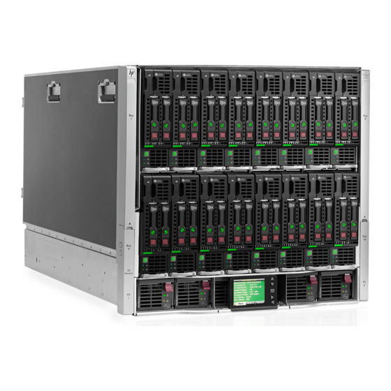
Page 72: Component Identification
Component identification HP BladeSystem c7000 Enclosure components Enclosure front components Item Description Device bays* Air intake slot (Do not block.) Power supply bay 1 Power supply bay 2 Power supply bay 3 Power supply bay 4 Insight Display Power supply bay 5 Power supply bay 6 Air intake slot (Do not block.) *For more information, see "Device bay numbering (on page 72)."... - Page 73 IMPORTANT: When looking at the rear of the enclosure, device bay numbering is reversed. Full-height device bay numbering Half-height device bay numbering Component identification 73...
-
Page 74: Power Supply Leds
Power supply LEDs Power LED 1 Fault LED 2 Condition (green) (amber) No AC power to the power supply Normal Power supply failure Power supply bay numbering Component identification 74... -
Page 75: Hp Bladesystem Insight Display
HP BladeSystem Insight Display Insight Display overview The Insight Display enables the rack technician to configure the enclosure initially. It also provides information about the health and operation of the enclosure. See the HP BladeSystem Onboard Administrator User Guide for additional information. The Insight Display background color varies with the condition of the enclosure health: •... - Page 76 Accessing the Insight Display on the HP BladeSystem c7000 Enclosure The Insight Display is located on the front of the HP BladeSystem c7000 Enclosure. The Insight Display slides from side to side to allow access to enclosure components. HP BladeSystem Insight Display components Item Description Function...
-
Page 77: Enclosure Rear Components
Enclosure rear components Item Description Fan bay 1 Fan bay 2 Fan bay 3 Fan bay 4 Fan bay 5 Interconnect bay 2 Interconnect bay 4 Interconnect bay 6 Interconnect bay 8 Onboard Administrator bay 2 OA tray Power supply exhaust vent (do not block) Fan bay 10 Fan bay 9 Fan bay 8... -
Page 78: Interconnect Bay Numbering
Interconnect bay numbering To support network connections for specific signals, install the interconnect module into the appropriate bay. Server blade signal Interconnect bay Interconnect bay label number NICs 1, 2, 3, and 4 1, 2 (embedded) Mezzanine 1 3, 4 Mezzanine 2 5, 6 and then 7, 8 Mezzanine 3... -
Page 79: Onboard Administrator Components
Onboard Administrator components Item Description Onboard Administrator bay 1 Onboard Administrator bay 2 (redundant, if used) Enclosure link-up port Enclosure link-down port Onboard Administrator LEDs and buttons Item Description Onboard Administrator UID LED Enclosure UID LED and UID button Onboard Administrator active LED Component identification 79... -
Page 80: Fan Bay Numbering
Item Description Onboard Administrator health LED Onboard Administrator reset button Fan bay numbering Fan LED LED color Fan status Solid green The fan is working. Solid amber The fan has failed. Flashing amber See the Insight Display screen. Component identification 80... -
Page 81: Hp Bladesystem C3000 Enclosure Components
HP BladeSystem c3000 Enclosure components Enclosure front components Item Description Device bays ("Device bay numbering" on page 72) CD/DVD-ROM drive blank or CD/DVD-ROM drive (optional) Onboard Administrator tray (reserved for future use) Insight Display Onboard Administrator tray containing Onboard Administrator 1. Device bay numbering Each enclosure requires interconnects to provide network access for data transfer. - Page 82 Full-height device bay numbering Half-height device bay numbering Component identification 82...
-
Page 83: Hp Bladesystem Insight Display Components
HP BladeSystem Insight Display components Item Description Function Insight Display screen Displays Main Menu error messages and instructions Left arrow button Moves the menu or navigation bar selection left one position Right arrow button Moves the menu or navigation bar selection right one position OK button Accepts the highlighted selection and navigates to the selected menu... - Page 84 Item Description Status Reset button — USB port — Health LED Green = Normal Red = OA firmware issue. See the HP Onboard Administrator User Guide on the HP website (http://www.hp.com/go/bladesystem/docum entation). Active LED Green = Primary OA module Off = Standby OA module UID LED Blue = Activated Off = Deactivated...
-
Page 85: Enclosure Rear Components
Pull the Insight Display out of the chassis to lock it into place, then tilt it for viewing. Enclosure rear components Item Description KVM module bay Interconnect bay 1 Fan bays ("Fan bay numbering" on page 86) Interconnect bay 2 Enclosure link-down port Enclosure link-up port Onboard Administrator 1/iLO port... - Page 86 Item Description Power supply bays ("Power supply bay numbering" on page 87) Interconnect bay 4 Interconnect bay 3 Fan bay numbering Fan LEDs LED color Fan status Solid green The fan is working. Solid amber The fan has failed. Flashing amber See the Insight Display screen.
-
Page 87: Power Supply Led
Power supply bay numbering Power supply LED Power LED Status No AC power to power supply units Green AC is present. Standby output is on, output is disabled. Green AC is present. Standby output is on, power supply DC output is on and Power supply failure (includes overvoltage and overtemperature) Component identification 87... - Page 88 Interconnect bay numbering To support network connections for specific signals, install the interconnect module in the appropriate bay. Server blade signal Interconnect bay Interconnect bay Notes number label NICs 1, 2, 3, and 4 — (embedded) Mezzanine 1 Four port cards connect to bay 2 Mezzanine 2 •...
-
Page 89: Software Tools And Solutions
Software tools and solutions Server blade diagnostic tools HP Insight Diagnostics HP Insight Diagnostics is a proactive server blade management tool, available in both offline and online versions, that provides diagnostics and troubleshooting capabilities to assist IT administrators who verify server blade installations, troubleshoot problems, and perform repair validation. -
Page 90: Array Diagnostic Utility
For NetWare: IML Viewer For Windows®: IML Viewer For Linux: IML Viewer Application • From within the iLO 2 user interface • From within HP Insight Diagnostics (on page 89) • From within the Onboard Administrator GUI For more information, see the HP BladeSystem Onboard Administrator User Guide on the HP website (http://www.hp.com/go/bladesystem/documentation). -
Page 91: Management Tools
For more information, see the HP website (http://www.hp.com/go/insightremotesupport). Management tools HP Systems Insight Manager HP SIM is a web-based application that allows system administrators to accomplish normal administrative tasks from any remote location, using a web browser. HP SIM provides device management capabilities that consolidate and integrate management data from HP and third-party devices. -
Page 92: Verifying Firmware Versions
If the server blade or enclosure firmware is not a version listed in one of the two columns of the compatibility matrix, then select a firmware update tool (online or offline) from the HP website (http://www.hp.com/go/bladesystemupdates). Use the firmware update tool to perform the firmware update. For more information on how to use the tool, see the documentation provided with the tool. -
Page 93: System Maintenance Tools
System maintenance tools Drivers IMPORTANT: Always perform a backup before installing or updating device drivers. The server includes new hardware that may not have driver support on all OS installation media. If you are installing a SmartStart-supported OS, use the SmartStart software and its Assisted Path feature to install the OS and latest driver support. -
Page 94: System Online Rom Flash Component Utility
• Works offline and online • Supports Microsoft® Windows® and Linux operating systems • Integrates with other software maintenance, deployment, and operating system tools • Automatically checks for hardware, firmware, and operating system dependencies, and installs only the correct ROM upgrades required by each target server For more information, see the HP Smart Update Manager User Guide. -
Page 95: Rom Update Utility
Option ROMPaqs have been retired as an upgrade delivery method for storage options. Firmware upgrades for storage options are now delivered using Smart Components and Smart Component deployment utilities. For additional information about the ROMPaq utility, see the server blade documentation or the HP website (http://www.hp.com/support). -
Page 96: Contacting Hp
Contacting HP Contacting HP technical support or an authorized reseller Before contacting HP, always attempt to resolve problems by completing the procedures in this guide. IMPORTANT: Collect the appropriate server information ("Server information you need" on page 97) and operating system information ("Operating system information you need"... -
Page 97: Server Information You Need
Server information you need Before contacting HP technical support, collect the following information: • Explanation of the issue, the first occurrence, and frequency • Any changes in hardware or software configuration before the issue surfaced • Third-party hardware information: Product name, model, and version Company name •... -
Page 98: Linux Operating Systems
Event logs Dr. Watson log (drwtsn32.log) if a user mode application, such as the Insight Agents, is having a problem IRQ and I/O address information in text format • An updated Emergency Repair Diskette • If HP drivers are installed: Version of the PSP used List of drivers from the PSP •... -
Page 99: Novell Netware Operating Systems
• If HP drivers are installed: Version of the PSP used List of drivers from the PSP (/var/log/hppldu.log) • A list of each third-party hardware component installed, with the firmware revisions • A list of each third-party software component installed, with the versions •... - Page 100 • Which software group selected for installation: End User Support, Entire Distribution, Developer System Support, or Core System Support • If HP drivers are installed with a DU: DU number List of drivers in the DU diskette • The drive subsystem and file system information: Number and size of partitions and logical drives File system on each logical drive •...
-
Page 101: Acronyms And Abbreviations
Acronyms and abbreviations Array Diagnostics Utility Command Line Interface DHCP Dynamic Host Configuration Protocol domain name system driver update field replaceable unit HP SIM HP Systems Insight Manager input/output Integrated Lights-Out iLO 2 Integrated Lights-Out 2 Integrated Management Log Internet Protocol Acronyms and abbreviations 101... - Page 102 interrupt request LDAP Lightweight Directory Access Protocol Media Access Control network interface card NVRAM non-volatile memory Onboard Administrator power distribution unit product ID POST Power-On Self Test ProLiant Support Pack SNMP Simple Network Management Protocol Secure Shell unit identification universal serial bus Acronyms and abbreviations 102...
-
Page 103: Index
Index connectors 72 contact information 97 contacting authorized reseller 96 ADU (Array Diagnostic Utility) 90 contacting HP 96, 97 alerts 16, 25, 26 contacting technical support 96 Array Diagnostic Utility (ADU) 90 controller display, LCD 83 authorized reseller 96 cooling errors 26 authorized technician 11 critical alerts 7 CSR (customer self repair) 96... - Page 104 external KVM monitor troubleshooting 62 IML (Integrated Management Log) 89 Important Safety Information document 10 fan bay numbering 77, 80, 86 information required 97 fan errors 26 Insight Diagnostics 89 fan failure troubleshooting 27 Insight Display 14, 75, 76, 84 fan LED 80, 86 Insight Display blue device error troubleshooting 66 fan status 86...
- Page 105 rack warnings 11 rear components 77, 85 management tools 91 replacing, midplane assembly 69 Microsoft operating systems 97 required information 97 midplane assembly 69 ROM update utility 95 midplane assembly replacement 69 ROM, updating 94 midplane assembly troubleshooting 69 ROMPaq utility 94 mouse problems 65 safety considerations 10 Novell NetWare 99...
- Page 106 troubleshooting, Onboard Administrator 46 troubleshooting, Onboard Administrator symptoms 46 troubleshooting, partner blade symptoms 44 troubleshooting, partner blades 43, 44 troubleshooting, power supply 31, 32 troubleshooting, server blade 35, 36, 38 troubleshooting, server blade symptoms 36 UID LED 16, 79 updating the firmware 91 upgrades compatibility matrix 91 USB drive key 94 using this guide 5...