Table of Contents
Advertisement
Quick Links
Advertisement
Chapters
Table of Contents
Troubleshooting

Related Manuals for Brother PT-2300


Summary of Contents for Brother PT-2300
- Page 1 SERVICE MANUAL MODEL: PT-2300/2310/2450...
- Page 2 SERVICE MANUAL MODEL: PT-2300/2310/2450...
- Page 3 PREFACE This publication is a service manual covering the specifications, theory of operation, disassembly/reassembly procedure, and troubleshooting and error message of the Brother PT- 2300/2310/2450. It is intended for service personnel and other concerned persons to accurately and quickly provide after-sale service for our PT-2300/2310/2450.
- Page 4 CHAPTER I SPECIFICATIONS...
-
Page 5: Table Of Contents
CONTENTS CHAPTER I SPECIFICATIONS................. I-1 MECHANICAL SPECIFICATIONS ................ I-1 1.1.1 External Appearance ..................I-1 1.1.2 Keyboard......................I-2 1.1.3 Display ......................I-2 1.1.4 Printing Mechanism..................I-2 1.1.5 Tape Cassette ....................I-3 1.1.6 Tape Cutter ....................I-3 ELECTRONICS SPECIFICATIONS ..............I-9 1.2.1 Character Generator.................. -
Page 6: Chapter Ispecifications
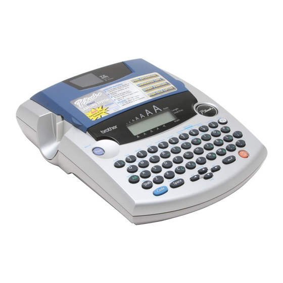
CHAPTER I SPECIFICATIONS MECHANICAL SPECIFICATIONS 1.1.1 External Appearance (PT-2300/2310) (PT-2450) Fig. 1.1-1 PT-2300/2310/2450 Dimensions (W x D x H) 194 x 242 x 65.5 mm (7.64" x 9.53" x 2.59") Weight Machine proper Approx. 900 g In package Approx. 1.6 kg (PT-2300/2450) Approx. -
Page 7: Keyboard
1.1.2 Keyboard Entry system Rubber key pad Number of alphanumeric and symbol keys Number of function keys 12 (including “On/Off ( ) ” key) Key arrangement See Fig. 1.1-2. Navigation dial (PT-2450) Rotary switch : 20 positions / cycle Set key : 1 1.1.3 Display Display type... -
Page 8: Tape Cassette
1.1.5 Tape Cassette Cassette Cartridge type Types of tape cassettes • Laminated tape cassette Laminate tape, ink ribbon, and adhesive base tape • Non-laminated tape cassette Non-laminate tape and ink ribbon • Instant lettering tape cassette Instant lettering tape and ink ribbon •... - Page 9 PT-2300/2310 U.S.A. Fig. 1.1-2 Key Arrangement (1)
- Page 10 PT-2450 BELGIUM Fig. 1.1-2 Key Arrangement (2)
- Page 11 PT-2450 FRENCH Fig. 1.1-2 Key Arrangement (3)
- Page 12 PT-2450 GERMAN Fig. 1.1-2 Key Arrangement (4)
- Page 13 PT-2450 U.K. Fig. 1.1-2 Key Arrangement (5)
-
Page 14: Electronics Specifications
ELECTRONICS SPECIFICATIONS 1.2.1 Character Generator Internal characters U.S.A. (PT-2300/2310) 179 characters U.K./ FRA/ BEL (PT-2450) 199 characters GER (PT-2450) 216 characters Internal font HELSINKI, BRUSSELS, FLORIDA, US (PT-2300/2310) HELSINKI, BRUSSELS, FLORIDA, BELGIUM, LOS ANGELS, SAN DIEGO, ISTANBUL, US (PT-2450) Internal memory Text buffer 99 characters (PT-2300/2310) 255 characters (PT-2450) - Page 15 CHAPTER II MECHANISMS...
- Page 16 CONTENTS CHAPTER II MECHANISMS................II-1 THEORY OF OPERATION ................... II-1 2.1.1 Print Mechanism .................... II-1 2.1.2 Roller Holder ASSY Setting & Retracting Mechanism........II-3 2.1.3 Tape & Ribbon Feed Mechanism..............II-4 2.1.4 Automatic Tape Cutter Mechanism..............II-6 2.1.5 Roller Holder ASSY & Cassette Cover Interlocking Mechanism...... II-7 DISASSEMBLY &...
- Page 17 [ 10 ] Installing the Tape Cassette and Tape Separator Stick ........ II-36 [ 11 ] Loading Batteries and Installing the Battery Lid ........... II-37 [ 12 ] Demonstration Print and Final Check ............II-38...
-
Page 18: Chapter Ii Mechanisms
CHAPTER II MECHANISMS THEORY OF OPERATION 2.1.1 Print Mechanism Structure of Thermal Head This machine uses thermal transfer printing. The thermal print head has a heat generator consisting of 112 heating elements (PT-2450 : 128 heating elements ) which are vertically aligned as shown in Fig. - Page 19 [For stamp tape cassettes] If the selected heating element(s) generates heat, the porous-stamp tape will be melted so that a pore (pores) will be formed in the tape. The tape is advanced and the next heating cycle is repeated, thus forming a character of pores on the tape. The printed stamp tape can be used as the face of a stamp.
-
Page 20: Roller Holder Assy Setting & Retracting Mechanism
2.1.2 Roller Holder ASSY Setting & Retracting Mechanism This mechanism consists of the roller release lever, roller holder release rod, and roller holder ASSY. The roller holder ASSY supports the platen and the tape feed sub roller so that they can move perpendicularly to the head ASSY and the tape feed roller, respectively, as well as rotating freely. -
Page 21: Tape & Ribbon Feed Mechanism
2.1.3 Tape & Ribbon Feed Mechanism This mechanism consists of a DC motor, gear train, and roller holder ASSY. Tape Feeding When you load a tape cassette and close the cassette cover, the tape feed roller inside the cassette and the tape feed sub roller in the roller holder ASSY sandwich the tape (the laminate tape and adhesive base tape when using laminated tape cassettes) inbetween, as described in Subsection 2.1.2. - Page 22 Adhesive Base Tape Feeding (only for laminated tape cassettes) A laminated tape cassette contains both a transparent laminate tape roll and a separate adhesive base tape roll. When a transparent laminate tape and an adhesive base tape pass through the contact point (between the tape feed roller and tape feed sub roller), they are then bonded together into a single, printed tape.
-
Page 23: Automatic Tape Cutter Mechanism
2.1.4 Automatic Tape Cutter Mechanism The cutter ASSY consists of a stationary blade and a movable blade driven by the cutter motor. Upon completion of printing and tape feeding, the CPU activates the cutter motor whose clockwise rotation is transmitted via the idle gears to the cutter moving gear. As the cutter moving gear rotates counterclockwise, its boss "X"... -
Page 24: Roller Holder Assy & Cassette Cover Interlocking Mechanism
2.1.5 Roller Holder ASSY & Cassette Cover Interlocking Mechanism Closing the cassette cover pushes down the roller release lever and brings the top of the lever into the hooked section provided on the inside of the cassette cover. As described in Subsection 2.1.2 “Roller Holder ASSY Setting & Retracting Mechanism”, the roller release lever shifts the roller holder release rod so that the roller holder ASSY is pressed towards the head ASSY side. -
Page 25: Disassembly & Reassembly
DISASSEMBLY & REASSEMBLY 2.2.1 Disassembly Procedure [ 1 ] Removing the Battery Lid and Batteries Turn the machine upside down. Press section "A" of the battery lid to remove, then take out batteries. Section “A” Battery lid Bottom cover Batteries Bottom cover Fig. -
Page 26: 2 ] Removing The Tape Cassette And Tape Separator Stick
[ 2 ] Removing the Tape Cassette and Tape Separator Stick Place the machine rightside up and open the cassette cover fully. Pull the tape cassette up and out of the machine. Cassette cover Tape cassette Fig. 2.2-2 Removing the Tape Cassette Pull the tape separator stick up. -
Page 27: 3 ] Removing The Bottom Cover
[ 3 ] Removing the Bottom Cover Close the cassette cover while pressing down section "B." Turn the machine upside down. Remove five screws from the bottom cover. Apply your fingers to the bottom cover and pull it up. Cassette cover Section “B”... - Page 28 Separate the bottom cover from the upper cover. Open the bottom cover to the left as shown below. Attach the tweezers onto the positive (+) and negative (-) terminals in order to discharge the capacitor mounted on the main PCB. Disconnect the power supply harness from the main PCB.
-
Page 29: Removing The Cassette Cover, Chassis Assy And Shield Plate
[ 4 ] Removing the Cassette Cover, Chassis ASSY and Shield Plate CAUTION: During the following job, handle the connectors and harnesses gently so as not to damage them. Take off the cassette cover from the upper cover. The roller release lever will pop up. Cassette cover Roller release lever Upper cover... - Page 30 Disconnect the following harnesses from the main PCB. - Cutter motor harness - Full cutter sensor harness - Photo interrupter harness Remove the harness the main PCB by melting the solder. - DC motor harness Disconnect the head cable from the main PCB. Remove the two screws of the chassis ASSY.
- Page 31 Head cable USB/IF harness (PT-2300/2310) Power supply harness Photo interrupter harness Full cutter sensor harness DC motor harness Switch ASSY harness Cutter motor harness Main PCB Fig. 2.2-9 Removing the Chassis ASSY and Shield Plate (3) II-14...
- Page 32 Disassembling the Chassis ASSY Removing the roller holder release rod, roller release lever, roller holder ASSY, and head ASSY Remove the retaining ring from the roller holder ASSY. Lift up the roller release lever as shown below and pull up the roller holder ASSY together with the roller release lever and roller holder release rod, making sure that the roller holder release spring does not go flying off.
- Page 33 Removing the DC motor ASSY Remove the two screws to remove the photo interrupter ASSY. Remove the encode gear from the DC motor ASSY. Remove two screws “b” from the chassis ASSY, then take off the DC motor ASSY. DC motor ASSY Screw “b”...
- Page 34 Removing the cutter ASSY, cutter motor ASSY, and full cutter sensor PRO ASSY WARNING: Be careful with the cutter blades. Remove screw “c” and take off the cutter ASSY. Remove the washer (by using a pin) and take off the cutter moving gear and cutter double gears.
-
Page 35: 5 ] Removing The Main Pcb And Rubber Key Pad
[ 5 ] Removing the Main PCB and Rubber Key Pad When you handle the PCB, it is recommended that an anti-static mat be used. If you have built up a static charge, touching the PCB without any anti-static control may damage the LSI and other electronic devices. - Page 36 Lift up the rubber key pad. Remove the emblem from the upper cover. (PT-2300/2310) Remove the navi dial from the upper cover. (PT-2450) (PT-2300/2310) Rubber key pad Upper cover Emblem (PT-2450) Rubber key pad Navi dial Upper cover Fig. 2.2-14 Removing the Rubber Key Pad II-19...
-
Page 37: 6 ] Removing The Switch Assy
[ 6 ] Removing the Switch ASSY Remove the switch ASSY harness from “A” position of the upper cover. Remove the switch ASSY from the bottom cover by pulling the three pawls outwards. Switch ASSY “A” Pawls Bottom cover Fig. 2.2-15 Removing the Switch ASSY [ 7 ] Removing the Blind Cover Remove the blind cover from the bottom cover by pulling the three pawls outwards. -
Page 38: 8 ] Removing The Power Supply Pcb
[ 8 ] Removing the Power Supply PCB Remove the positive (+) and negative (-) terminals of the battery power cords from the bottom cover. Note: When handling those terminals, do not grip the cords but the terminal plates. Remove the pad from the rib on the bottom cover. (PT-2300/2310) Remove the one screw from the power supply PCB. -
Page 39: 9 ] Removing The Battery Terminals
[ 9 ] Removing the Battery Terminals Remove the right-hand battery terminal as shown below (left). As shown below (right), remove the left-hand battery terminals while pressing section “A” with the tip of a flat screwdriver. Battery terminal Section “A” Battery terminal Battery terminal (Front) -
Page 40: Reassembly Procedure
2.2.2 Reassembly Procedure [ 1 ] Installing the Battery Terminals Place the bottom cover upside down and fit two battery terminals into the bottom cover as shown below (left). Make sure that each of their pawled sections “A” catches the bottom cover. -
Page 41: 2 ] Installing The Power Supply Pcb
[ 2 ] Installing the Power Supply PCB Fit the positive (+) and negative (-) terminals of the battery power cords into the bottom cover. Note 1: When handling those terminals, do not grip the cords but the terminal plates. Note 2: Route the battery power cords through the two ribs provided on the bottom cover. - Page 42 (PT-2300/2310) (PT-2450) Fig. 2.2-21 Installing the Power Supply PCB (2)
-
Page 43: 3 ] Installing The Blind Cover
[ 3 ] Installing the Blind Cover Fit three holes “A” of the blind cover over the pins provided on the bottom cover and push down the blind cover until pawls “B” catch the hooks on the bottom cover. Blind cover Pawl “B”... -
Page 44: Installing The Rubber Key Pad
[ 5 ] Installing the Rubber Key Pad Place the rubber key pad so that it is fitted over the three bosses and two pins provided on the upper cover. (PT-2300/2310) Rubber key pad Boss Upper cover Boss Emblem Boss (PT-2450) Rubber key pad Navi dial... -
Page 45: 6 ] Installing The Main Pcb
[ 6 ] Installing the Main PCB Pull the positions “A” outwards to put the LCD with the main PCB into the position “B”. Check that there is no foreign material or dust on the key contacts on the main PCB. Note 1: Make sure that the two latches of the upper cover catch the main PCB. -
Page 46: Installing The Chassis Assy And Shield Plate
[ 7 ] Installing the Chassis ASSY and Shield Plate If the chassis ASSY has been disassembled, assemble the components by referring to the following pages. Pull down the roller release lever to the vertical position and set the chassis ASSY onto the upper cover. - Page 47 Solder the six switch ASSY harnesses onto the main PCB. Switch ASSY harness Black Green Upper cover Yellow Blue Main PCB Orange Note: Be careful to the direction of the switch ASSY harness and not to stick out from the designated place when soldering switch ASSY harness.
- Page 48 Assembling the Components of the Chassis ASSY Installing the full cutter sensor PRO ASSY, cutter motor ASSY, and cutter ASSY Fit the actuator into the hole provided in the chassis ASSY and turn it clockwise. Secure the full cutter sensor PRO ASSY to the chassis ASSY with screw “e”. Tightening torque: 147±49 mN•m (1.5±0.5 kg•cm) Secure the cutter motor ASSY with two screws “d”...
- Page 49 Installing the DC motor ASSY Install the DC motor ASSY to the chassis ASSY with two screws “b”, taking care not to damage the gear. Tightening torque: 100 to 200 mN•m (1 to 2 kg•cm) Squeeze the encode gear so that it is engaged with the double gear with taking care not to damage the gear.
- Page 50 Installing the head ASSY, roller holder ASSY, and roller holder release rod, roller release lever Secure the head ASSY to the chassis ASSY with screw “a”. Tightening torque: 490±196 mN•m (5±2 kg•cm) Apply half of a rice-sized pinch of grease (Silicon grease G501) to the roller holder ASSY (slideway for the roller holder release rod).
-
Page 51: 8 ] Installing The Bottom Cover
[ 8 ] Installing the Bottom Cover Connect the power supply harness to the main PCB. Connect the USB/IF harness to the main PCB (PT-2300/2310). Align the front edge of the bottom cover with that of the upper cover, then push down the bottom cover until it snaps into place. - Page 52 Secure the bottom cover with five screws. Tightening torque: 392±98 mN•m (4±1 kg•cm) Screws Bottom cover Screw Screw Fig. 2.2-33 Installing the Bottom Cover (2)
-
Page 53: 9 ] Installing The Cassette Cover
[ 9 ] Installing the Cassette Cover Place the machine rightside up. Lift up the roller release lever. Hold the cassette cover at an angle shown below and slide down its hinges until they become fitted into the bottoms of the grooves provided in the bottom cover. Close the cassette cover. - Page 54 [ 11 ] Loading Batteries and Installing the Battery Lid Load batteries. Fit the front end of the battery lid into the bottom cover and push down the lid. Batteries Bottom cover Battery Lid Bottom cover Fig. 2.2-36 Loading Batteries and Installing the Battery Lid...
- Page 55 [ 12 ] Demonstration Print and Final Check Following items are verified lastly after completed the assembly. Press the “On/Off ( ) ” key. While holding down the “Code” key, press the “BS ( ) ” key to cancel data previously entered.
- Page 56 7.2.1. Information Mode Displays as shown in Fig. 2 when entered into the inspection mode, or when depressed “1” key (excluding when in the key inspection mode). The information mode performs, by pressing “ ” key, the country display, head rank display, and the input electrical power checks.
- Page 57 7.2.1.4. Power Supply Voltage Check Display (Inspection voltage: 12.0 ± 0 V) Displays “ ” when within the required input voltage range. Displays “ X ” when out of the range. Country Head Margin Voltage Specifications Rank Rank Display Country display : U.S.A./CAN Head rank display : B rank Margin rank display : 0 rank Voltage display : No problem...
- Page 58 7.2.3. Key Inspection Mode “3” Key Here, check the key input function. Display of Fig. 9 is indicated when depressed “ ” key or depressed “3” key in the display of Fig. 8. Fig. 9 Shifts to the Key Inspection Mode when depressed “ ”...
- Page 59 7.2.4. Cut Mode “4” Key Here, check the cutter function. Display of Fig. 12 is indicated when depressed “ ” key or depressed “4” key in the display of Fig. 13 (except while in the Key Inspection Mode). Fig. 14 Fig.
- Page 60 7.2.5. PRINT 1 Mode “5” Key Here, check the print quality, tape length accuracy and print length accuracy. Display of Fig. 18 is indicated when depressed “ ” key or depressed “5” key in the display of Fig. 17 (except while in the Key Inspection Mode). Fig.
- Page 61 7.2.6. PRINT 2 Mode “6” Key This mode checks the more detailed print quality than PRINT 1. Fig. 19 is displayed when depressed “6” key (except while in the Key Inspection Mode). Fig. 19 The function is started when depressed “ ”...
- Page 62 7.2.7. MOTOR Mode “7” Key: Used for the DC motor speed adjustment. This mode is used only when the print length accuracy or tape feed length accuracy deviates from the specification. Display of Fig. 20 is indicated when depressed “7” key. Fig.
- Page 63 7.2.8. The descriptions about section ‘AD Check Mode “8” Key’ and ‘USB Setting Mode “0” Key (Only PT-2300/2310)’ are omitted because they are not related to the inspection procedure. 7.2.9. Encoder Reading Check Mode “E” Key This mode checks that there is no problem to read the encoder or no phase shift. Fig. 26 is displayed.
- Page 64 CHAPTER III ELECTRONICS...
- Page 65 CONTENTS CHAPTER III ELECTRONICS ................III-1 OUTLINE OF CONTROL ELECTRONICS ............III-1 3.1.1 Configuration of the Electronic Part ..............III-1 3.1.2 Main PCB....................... III-1 3.1.3 Power Supply PCB ..................III-1 3.1.4 Cassette Sensor ..................... III-1 3.1.5 DC Motors ...................... III-1 3.1.6 Thermal Print Head ..................
- Page 66 3.2.14 LCD Driver Circuit ..................III-16 3.2.15 USB Interface Circuit (PT-2300/2310) ............III-17 POWER SUPPLY PCB ..................III-18...
-
Page 67: Chapter Iii Electronics
CHAPTER III ELECTRONICS OUTLINE OF CONTROL ELECTRONICS 3.1.1 Configuration of the Electronic Part Fig. 3.1-1 shows a block diagram of the control electronics of the PT-2300/2310/2450. The control electronics consists of three printed circuit boards (main PCB, cassette sensor PCB, and power supply PCB), two DC motors, and a thermal print head assembly. -
Page 68: Main Pcb
MAIN PCB 3.2.1 Block Diagram Fig. 3.2-1 shows a block diagram of the main PCB. The main PCB consists of the following: ROM (Masked) Key contacts matrix and solder points Power ON/OFF circuit and power saving circuit DC motor driver circuit Cutter motor driver circuit Thermal head drive circuit Voltage detector circuit and temperature sensor circuit... -
Page 69: Cpu
3.2.2 The CPU (U11 : H8S/2324) is a 16-bit CMOS microprocessor which integrates a 32-kilobyte RAM. The external data bus is 16 bits, through which the CPU controls the ROM. The internal data bus is 16 bits. Fig. 3.2-2 CPU and ROM 3.2.3 ROM (See Fig. -
Page 70: Key Contacts Matrix And Solder Points
3.2.4 Key Contacts Matrix and Solder Points [ 1 ] Key contacts matrix On the main PCB is a key contacts matrix that is a set of 50 carbon-printed key contact patterns except for the “On/Off ( )” key. (Refer to Fig. 3.2-5.) Each contact pattern has a pair of electric nodes. -
Page 71: 2 ] Solder Points
[ 2 ] Solder points Fig. 3.2-5 shows a circuit diagram relating to the key pad and solder points. Solder points 1 through 5 customize the machine for the destination. Solder points A through C are reserved for the future use for the individual thermal head properties. Three margin cutting modes, S, M and L are provided. -
Page 72: Power On/Off Circuit And Power Saving Circuit
3.2.5 Power ON/OFF Circuit and Power Saving Circuit [ 1 ] Power ON/OFF circuit Fig. 3.2-6 shows a circuit diagram of the power “On/Off ( )” key. The CPU processes the “On/Off ( )” key state in a sequence quite different from other keys although it is on the key pad. Fig. -
Page 73: Power Saving Circuit
Powering-on sequence (See Fig. 3.2-7.) 1) Interrupted by IRQO, the CPU starts the chattering elimination program module. 2) If pin 38 is Low for 10 ms, the CPU recognizes the “On/Off ( )” key as being pressed and then transfers the control to the main program module. If pin 38 is High, the CPU interprets the input as a noise and waits for the next IRQO. -
Page 74: Dc Motor Driver Circuit
3.2.6 DC Motor Driver Circuit Fig. 3.2-8 shows a driver circuit of the DC motor which feeds tapes and ink ribbon. Through PG3, the CPU issues a start/stop control signal to the motor driver circuit. Fig. 3.2-9 shows the control signal and drive current waveforms. The DC motor integrates an electronic governor circuit which handles the variation of the drive source voltage (VBT), in order to keep the rotation speed constant. - Page 75 The encoder fixed onto the motor detects the rotation by the two photo interrupters. While the pulses of P52 detect the rotation angle, the pulses of P51 which is dephased with P52 by 90 degrees detect the rotation direction. When five pulses of P52 are input, 1 dot is printed. Fig.
-
Page 76: Cutter Motor Driver Circuit
3.2.7 Cutter Motor Driver Circuit Fig. 3.2-10 shows a driver circuit of the DC motor which cuts tape after a sequence of printing. The CPU (U11) activates the transistor array (U2: BA6285) through P31 (pin 61) and P32 (pin 62) to drive the cutter motor. -
Page 77: Thermal Head Drive Circuit
3.2.8 Thermal Head Drive Circuit Fig. 3.2-11 shows the thermal head drive circuit. The print head integrates a heat generator (consisting of 128 heating elements vertically aligned in 180 dpi) and a pair of built-in driver ICs which are designed for 64-element control and cascaded with each other. U5 (TC74HC32) is a voltage level converter converting from 3.3V to 5V. -
Page 78: Voltage Detector Circuit And Temperature Sensor Circuit
3.2.9 Voltage Detector Circuit and Temperature Sensor Circuit Fig. 3.2-12 show the voltage detector circuit and the ambient sensor circuit, each of which is composed of a resistor network. [ 1 ] Voltage detector circuit This circuit, which is composed of divider resistors R87 and R90, steps down the power source MTV fed from batteries or the AC adapter output and feeds the output to the A/D input port AN1 on the CPU. -
Page 79: Cassette Sensor Circuit
3.2.10 Cassette Sensor Circuit Fig. 3.2-13 shows the cassette sensor circuit which reads the five sensor switches. Loading a tape cassette turns on some of those five switches while keeping other switches off depending upon the ID encoding holes provided in the tape cassette currently loaded. If an encoding ID hole is closed, the corresponding sensor switch goes on. -
Page 80: Cutter Sensor Circuit
3.2.11 Cutter Sensor Circuit Fig. 3.2-14 shows the cutter sensor circuit. When the cutter is opened, the movable blade activates the cutter sensor actuator which presses the cutter sensor switch to close the switch contact. If the cutter motor is driven, the linked movable blade moves to cut tape, releasing the cutter sensor to open the switch contact. -
Page 81: Reset Circuit
3.2.13 Reset Circuit Fig. 3.2-16 shows the reset circuit. This circuit prevents the CPU and logic circuitry from malfunctioning in powering-on and -off sequences or when the battery output drops abnormally. Fig. 3.2-16 Reset Circuit Fig. 3.2-17 shows the reset timing when the power is first applied or cut off or when the battery output drops below the specified level. - Page 82 3.2.14 LCD Driver Circuit The LCD driver (#2: NJU6450) consists of a 2560-bit display data RAM, CPU interface circuit, instruction execution unit, CR oscillation circuit, 16 source drivers, and 61 segment drivers. It stores data sent from the CPU into the embedded 2560-bit RAM and drives the dot-matrix LCD elements through the source/segment drivers.
- Page 83 3.2.15 USB Interface Circuit (PT-2300/2310) Fig. 3.2-19 shows the USB interface circuit. U4 is a USB chip meeting requirements of the high speed mode, and data is transmitted or received with a computer via two data signal cables D+ and D-. Fig.
- Page 84 POWER SUPPLY PCB Fig. 3.3-1 shows a circuit diagram of the power supply PCB. C1 for the logic circuitry and the thermal print head and motor drive sources. Connecting the AC adapter plug with the AC jack J1 cuts off the power fed from the batteries and feeds power from the AC adapter.
- Page 85 CHAPTER IV TROUBLESHOOTING AND ERROR MESSAGE...
- Page 86 CONTENTS ....... CHAPTER IV TROUBLESHOOTING AND ERROR MESSAGE IV-1 TROUBLESHOOTING ..................IV-1 4.1.1 Precautions ....................IV-1 4.1.2 After Repairing ....................IV-1 4.1.3 Troubleshooting Flows..................IV-2 [ 1 ] Tape feeding failure..................IV-2 [ 2 ] Printing failure ..................... IV-5 [ 3 ] Powering failure (Nothing appears on the LCD.) ..........
-
Page 87: Troubleshooting
CHAPTER TROUBLESHOOTING 4.1 TROUBLESHOOTING This section gives the service personnel some of the troubleshooting procedures to be followed if an error or malfunction occurs with this machine. It is impossible to anticipate all of the possible troubles which may occur in future and determine the troubleshooting procedures, so this chapter covers some sample troubles. -
Page 88: Troubleshooting Flows
4.1.3 Troubleshooting Flows [ 1 ] Tape feeding failure IV - 2... - Page 89 IV - 3...
- Page 90 IV - 4...
-
Page 91: 2 ] Printing Failure
[ 2 ] Printing failure IV - 5... - Page 92 IV - 6...
- Page 93 IV - 7...
-
Page 94: 3 ] Powering Failure (Nothing Appears On The Lcd
[ 3 ] Powering failure (Nothing appears on the LCD.) IV - 8... - Page 95 IV - 9...
- Page 96 IV - 10...
-
Page 97: 4 ] No Key Entry Possible
[ 4 ] No key entry possible IV - 11... -
Page 98: 5 ] Tape Cutting Failure
[ 5 ] Tape cutting failure IV - 12... -
Page 99: 6 ] Interface Port Failure (Pt-2300/2310
[ 6 ] Interface port failure (PT-2300/2310) IV - 13... -
Page 100: 7 ] Abnormal Lcd Indication
[ 7 ] Abnormal LCD indication IV - 14... -
Page 101: 8 ] Tape Cassette Type Not Identified
[ 8 ] Tape cassette type not identified IV - 15... -
Page 102: Error Message
4.2 ERROR MESSAGE 4.2.1 Error Message List The error message list is shown as follows. Error Conditions Display U.K./BELGIUM FRENCH GERMAN U.S.A. CANADA Check system find any PROBLEME ROM - PROBLÈME problem in ROM. PROBLEM! ROM! FEHLER! PROBLEM! ROM! Wrong adaptor (higher WRONG CHANGER FALSCHER... - Page 103 Error Conditions Display U.K./BELGIUM FRENCH GERMAN U.S.A. CANADA When the soldered SOLDER SOLDER SOLDER SOLDER SOLDER position is not correct. The cursor is not below a INVAL . CARACTÈRE number when you hold CHRS! INVALIDE! down “Code” and press “Number”. The cursor is in the final CAN’T of the sentence when you...
- Page 104 Error Conditions Display U.K./BELGIUM FRENCH GERMAN U.S.A. CANADA When less than minimum DIGIT DIGITS MIND. 4 4 digits are entered as MIN .! MINIMUM! ZIFFERN! barcode data. If the inputted number of INPUT CODE DATEN digits is less than its WHOLE CODE INCOMPLET!
- Page 105 APPENDICES 1. Software to Write the Serial Number 2. Circuit Diagrams A: Main PCB PT-2300/2310 B: Main PCB PT-2450EU (DEU/GER/BEL) C: Main PCB PT-2450FR (FRA) D: Sub PCB (PT-2300/2310) E: Sub PCB (PT-2450)
- Page 106 APPENDICES 1 SOFTWARE TO WRITE THE SERIAL NUMBER Operation of the software to write the serial number into PT-2300/2310 General This software writes the serial number into the EEPROM mounted on the main PCB when replacing the main PCB. <Operation Procedure> * Before writing the serial number •...
- Page 107 Fig. 2 Enter 9 digits of the serial number described in the rating plate on the machine in the [Serial number: ] box. * For example, when ‘U60043-G1J497587’ is described in the rating plate, enter the last 9 digits. After entering the serial number, click the [Write] button. The serial number entered in the [Serial number: ] box is written into the machine, and the message such as ‘Complete to write the serial number.
- Page 113 Aug., 2001 8V2020BE0 Printed in Japan...