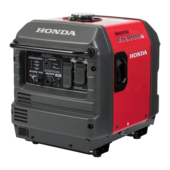
Honda EU3000is Owner's Manual
Hide thumbs
Also See for EU3000is:
- Owner's manual (108 pages) ,
- Information (28 pages) ,
- Owner's manual (100 pages)

Related Manuals for Honda EU3000is


Summary of Contents for Honda EU3000is
- Page 1 ® Owner's Manual GENERATOR EU2600i • EU3000is ©1998 Honda Motor Co., Ltd. — All Rights Reserved...
- Page 2 Honda Motor Co., Ltd. reserves the right, however, to discontinue or change specifications design at any time without notice and without incurring any obligation whatever.
- Page 3 Honda servicing dealer is specially trained in servicing Honda generators. Your Honda servicing dealer is dedicated to your satisfaction will be pleased to answer your questions concerns. Best Wishes, Honda Motor Co., Ltd.
- Page 4 A FEW WORDS ABOUT SAFETY Your safety and the safety of others are very important. And using this generator safely is an important responsibility. To help you make informed decisions about safety, we have provided operating procedures and other information on labels and in this manual.
-
Page 5: Table Of Contents
CONTENTS SAFETY ....................................Safety Label Locations ................Safety Information ............... COMPONENT IDENTIFICATION ....................CONTROLS ..............Engine Switch (EU3000is) ..............Engine Switch (EU2600i) ..................Recoil Starter ................... Fuel Valve Choke Knob ..................Eco-throttle Switch ................Light ................ Output Indicator Light ..............Overload Indicator ................ - Page 6 ..................38 MAINTENANCE .
-
Page 7: Safety
SAFETY SAFETY LABEL LOCATIONS These labels warn you of potential hazards that can cause serious injury. Read them carefully. If a label comes off or becomes hard to read, contact your Honda generator dealer for a replacement. - Page 8 WARNING GASOLINE IS HIGHLY I’IAMMAELE AND EXPLOSIVE. YOU CAN BE BURNED OK SERIOUSLY INJURED WHEN HAJiDLlNG FUEL. I STOP THE ENGINE AND KEEP HEAT, SPARKS, AND FLAME AWAY. I HANDLE t’Ua ONLY OUTDOORS. I DO NOT FILL THE FUEL TANK ABOVE THE UPPER LIMIT LINE. I WIPE UP SPILLS IMMEDIATELY.
-
Page 9: Safety Information
SAFETY INFORMATION Honda generators are designed to give safe and dependable service if operated according to instructions. Read and understand this owner’s manual before operating your generator. help prevent accidents by being familiar with your generator’s controls, and by observing safe operating procedures. - Page 10 Electric Shock Hazards The generator produces enough electric power to cause a serious shock or electrocution if misused. Using a generator or electrical appliance in wet conditions, such as rain or snow, or near a pool or sprinkler system, or when your hands are wet, could result in electrocution.
-
Page 11: Component Identification
COMPONENT IDENTIFICATION DC CIRCUIT DC RECEPTACLE PROTECTOR OUTPUT PARALLEL OPERA OUTLETS INDICATOR LIGHT OVERLOAD OIL ALERT INDICATOR LIGHT ENzll:2/ /Yp/?Gg\\J FUEL VALVE LEVER ECO-THROTTLE StilTCH AC RECEPTACLES < STAND TYPE > <WHEEL TYPE>... - Page 12 SPARK PLUG CAP MUFFLER FRONT HANDLE OIL FILLER CAP/ xzib DIPSTICK OIL DRAIN PLUG OIL MAINT LEFT-SIDE MAINTENANCE COVER FUEL TANK CAP STARTER GRIP HANDLE GROUND TERMINAL *Record the frame serial number for your future reference. Refer to this serial number when ordering parts, and when making technical...
-
Page 13: Controls
CONTROLS ENGINE SWITCH (EU3000is) To start and stop the engine. Key position: OFF: To stop the engine. Key can be removed/inserted. To run the engine after starting. START: To start the engine by operating the starter motor. ENGINE SWlTCH Return the key to the ON position once the engine has started. -
Page 14: Recoil Starter
RECOIL STARTER To start the engine, pull the starter grip lightly until resistance is felt, then pull briskly. Do not allow the starter grip to snap back against the engine. Return it gently to prevent damage to the starter. STARTER GRIP FUEL VALVE The fuel valve is located... -
Page 15: Choke Knob
CHOKE KNOB The choke knob opens and closes the choke valve in the carburetor. Pulling the choke knob to the CLOSED position enriches the fuel mixture for starting a cold engine. Pushing the choke knob to the OPEN position provides the correct fuel mixture for operation... -
Page 16: Output Indicator Light
OUTPUT INDICATOR LIGHT The output indicator light (green) is illuminated when the generator operating normally. It indicates that generator is producing electrical power at the receptacles. OUTPUT INDICATOR LIGHT (GREEN) OVERLOAD INDICATOR LIGHT If the generator is overloaded (see pages 64 and65), or if there is a short circuit in a connected... -
Page 17: Oil Alert@ System
(see page24). A special cable/receptacle assembly (optional equipment) is required parallel operation. This special cable/ receptacle assembly be purchased from authorized Honda generator dealers. SPECIAL CABLE/RECEPTACLE ASSEMBLY ;Al;l\;tL OPERATION FOR PARALLEL OPERATION (optional parts) -
Page 18: Dc Receptacle
DC RECEPTACLE DC receptacle should ONLY be used charging 12-volt automotive type batteries. DC CIRCUIT PROTECTOR DC circuit protector automatically shuts off the DC battery charging circuit when the DC charging circuit is overloaded, when there is a problem with the battery, or when the connections between the battery and the generator... -
Page 19: Ground Terminal
GROUND TERMINAL The generator ground terminal is connected to the frame of the generator, the metal non-current-carrying parts of the generator, the ground terminals of each receptacle. Before using the ground terminal, consult a qualified electrician, electrical inspector or local agency having jurisdiction for local codes... -
Page 20: Generator Use
Honda generator dealers. Improper connections to a building’s electrical system can allow electrical current from the generator to backfeed into the utility lines. Such backfeed may electrocute utility company workers... -
Page 21: Ac Applications
AC APPLICATIONS Before connecting an appliance or power cord to the generator: Make sure that it is in good working order. Faulty appliances power cords can create a potential for electrical shock. If an appliance begins to operate abnormally, becomes sluggish stops suddenly, turn it off immediately. -
Page 22: Ac Operation
AC OPERATION 1. Start the engine and make sure the output indicator light (green) comes on (see page35 and36). 2. Plug in the appliance. Most motorized appliances require more than their rated wattage startup. PLUG OUTPUT INDICATOR LIGHT (GREEN) OVERLOAD INDICATOR LIGHT (RED) If the generator... - Page 23 (red) may come on. This is normal if the overload indicator light (red) goes off after about four (4) seconds. If the overload indicator light (red) stays on, consult your Honda generator dealer.
-
Page 24: Ac Applications In Parallel Operation
AC APPLICATIONS IN PARALLEL OPERATION Before connecting an appliance or power cord to the generator: Make sure that it is in good working order. Faulty appliances power cords can create a potential for electrical shock. If an appliance begins to operate abnormally, becomes sluggish... - Page 25 For continuous operation, do not exceed the rated power. Rated power in parallel operation EU2600i: 4.8 kVA EU3000is: 5.6 kVA The total power requirements (VA) of all appliances connected must be considered. Appliance and power tool manufacturers usually list rating information near the model number or serial number.
-
Page 26: Ac Operation In Parallel Operation
AC OPERATION IN PARALLEL OPERATION 1. Connect the special cable/receptacle assembly for parallel operation to the two generators, as shown. 2. Hang the receptacle box of the special cable/receptacle assembly the front handle of one generator. FRONT HANDLE RECEPTACLE BOX SPECIAL CABLE/RECEPTACLE ASSEMBLY FOR PARALLEL OPERATION (optional parts) - Page 27 3. Start the engines and make sure the output indicator lights (green) come on (see pages35and36). OUTPUT INDICATOR LIGHT (GREEN) OVERLOAD INDICATOR LIGHT (RED) 4. Plug in the appliance into the AC receptacle of the receptacle box. Most motorized appliances require more than their rated wattage startup.
-
Page 28: Dc Operation
DC OPERATION DC receptacle should ONLY be used charging 12-volt automotive type batteries. DC output will vary according to the position of the Eco-throttle switch. When the Eco-throttle switch is turned to the ON position and the AC output is not used, the DC current will be about one-third of the rated current. - Page 29 2. Plug battery charging cable into DC receptacle of the generator. 3.Connect the red lead of the battery charging cable to the battery positive (+) terminal and the black lead to the battery negative (--) terminal. YELLOW INDICATOR DC RECEPTACLE DC CIRCUIT PROTECTOR ERY CHARGING CABLE RED LEAD...
- Page 30 If the circuit protector continues to go OFF, discontinue charging and see your authorized Honda generator dealer. Disconnecting the battery charging cable: 1. Stop the engine. 2. Disconnect the black lead of the battery charging cable from the battery negative (-) terminal.
-
Page 31: Eco-Throttle System
ECO-THROTTLE SYSTEM With the switch in the ON position, engine speed is automatically reduced when all loads are turned OFF or disconnected. When appliances are turned ON or reconnected, the engine returns to the proper speed to power the electrical load. -
Page 32: High Altitude Operation
HIGH ALTITUDE OPERATION At high altitude, the standard carburetor air-fuel mixture will be too rich. Performance will decrease, and fuel consumption will increase. very rich mixture will also foul the spark plug and cause hard starting. High altitude performance can be improved by specific modifications to the carburetor. -
Page 33: Pre-Operation Check
PRE-OPERATION CHECK ENGINE OIL piciq Engine oil is a major factor affecting engine performance and service life. Non detergent and 2-stroke engine oils will damage the engine and are not recommended. Check the oil level BEFORE EACH USE with the generator on a level surface and the engine stopped. -
Page 34: Refueling
REFUELING Fuel tank capacity: US gal , 2.86 Imp gal) 13.0 !i! (3.43 With the engine stopped, check the fuel level gauge. Refill the fuel tank if the fuel level is low. Gasoline is highly flammable and explosive. You can be burned or seriously injured when handling fuel. -
Page 35: Fuel Recommendations
If spark knock or pinging persists, see an authorized Honda generator dealer. 1 NOTICE ( Running the engine with persistent spark knock or pinging can cause engine damage. Running the engine with persistent... - Page 36 Oxygenated Fuels Some conventional gasolines are being blended with alcohol or an ether compound. These gasolines are collectively referred to as oxygenated fuels. To meet clean air standards, some areas of the United States and Canada use oxygenated fuels to help reduce emissions.
-
Page 37: Starting The Engine
STARTING THE ENGINE Electric starting (EU3000is only): 1. Make sure that appliances are disconnected from receptacles. 2. Turn the fuel valve lever to the ON position. 3.To start a cold engine, pull the choke knob out to the CLOSED posrtron. To restart a warm engine, leave the choke knob in the OPEN position. - Page 38 Manual starting: 1. Make sure that all appliances are disconnected from receptacles. 2. Turn the fuel valve lever to the ON position. 3.To start a cold engine, pull the choke knob out to the CLOSED position. To restart a warm engine, leave the choke knob in the OPEN position.
-
Page 39: Stopping The Engine
STOPPING THE ENGINE In an emergency: l.To stop the engine in an emergency, turn the engine switch to the OFF position. In normal use: 1. Unplug appliances from the generator receptacles. In parallel operation, unplug the appliance from the receptacle of the special cable/receptacle assembly... -
Page 40: Maintenance
Other service tasks that are more difficult, or require special tools, are best handled by professionals and are normally performed by a Honda technician or other qualified mechanic. The maintenance schedule applies to normal operating conditions. If you... -
Page 41: Safety
MAINTENANCE SAFETY Some of the most important safety precautions follow. However, cannot warn of every conceivable hazard that can arise performing maintenance. Only you can decide whether or not you should perform a given task. Failure to properly follow maintenance instructions and precautions can cause you to be seriously hurt or killed. -
Page 42: Emission Control System Information
The following instructions and procedures must be followed in order to keep the emissions from your Honda engine within the emission standards. Tampering and Altering Tampering with or altering the emission control system... - Page 43 Afterburning (backfiring). Black exhaust smoke or high fuel consumption. Replacement Parts The emission control systems on your Honda engine were designed, built, and certified to conform with EPA and California emission regulations. recommend use of genuine...
-
Page 44: Maintenance Schedule
(2)These items should be serviced by an authorized Honda generator dealer, unless the owner has the proper tools and is mechanically proficient. See the Honda Shop Manual. (3)For commercial use, log hours of operation to determine proper maintenance intervals. -
Page 45: Engine Oil Change
ENGINE OIL CHANGE Drain the oil while the engine is warm to assure rapid and complete draining. 1. Open and remove the oil maintenance cover. 2. Remove the drain plug and sealing washer, remove the oil filler cap, and drain the oil. 3. -
Page 46: Air Cleaner Service
AIR CLEANER SERVICE A dirty air filter will restrict air flow to the carburetor. To prevent carburetor malfunction, service the air cleaner regularly. Service more frequently when operating the generator in extremely dusty areas. Using gasoline or flammable solvent to clean the air filter can cause a fire or explosion. - Page 47 c. Soak the foam air filter in clean engine squeeze excess oil. The engine will smoke during initial startup if too much oil is left in the foam air filter. d. Reinstall the foam air filter to the air cleaner cover. PAPER AIR FILTER 4.
-
Page 48: Spark Plug Service
SPARK PLUG SERVICE In order to service the spark plug, you will need a spark plug wrench (commercially available). Recommended spark plugs: BPR5ES (NGK) WIGEPR-U (DENSO) To ensure proper engine operation, the spark plug must be properly gapped and free of deposits. If the engine has been running, the muffler... - Page 49 6.Visually inspect the spark plug. Discard it if the insulator is cracked or chipped. Clean the spark plug with a wire brush if it is to be reused. 7. Measure the plug gap with a feeler gauge. Correct as necessary by carefully bending the side electrode.
-
Page 50: Fuel Sediment Cup Cleaning
FUEL SEDIMENT CUP CLEANING The sediment cup prevents dirt or water which may be in the fuel tank from entering the carburetor. If the engine has not been run for a long time, the sediment cup should be cleaned. 1, Turn the engine switch to the OFF position. 2. - Page 51 Remove the sediment cup by turning it counterclockwise. 8. Clean the sediment cup, O-ring, and filter in nonflammable or high flash point solvent. 9. Reinstall the filter, O-ring, and sediment cup. lO.Reinstall the air cleaner base, and connect the breather hose with the air cleaner base.
-
Page 52: Spark Arrester Maintenance
SPARK ARRESTER MAINTENANCE If the generator has been running, the muffler will be very hot. Allow to cool before proceeding. The spark arrester must be serviced every 100 hours to maintain efficiency. I. Remove the four 6 mm cap nuts, and remove the rear cover. 2.Remove the four 6 mm... - Page 53 6. Remove the three 5 mm bolts, and remove the exhaust tail pipe and the spark arrester. EXHAUST TAIL PIPE SPARK ARRESTER 5 mm BOLTS 7. Use a brush to remove carbon deposits from the spark arrester screen. 8. Inspect the screen for breaks or tears and replace it if necessary. 9.
- Page 54 lO.lnstall the lower muffler protector, the rear under plate and the rear handle in the reverse order of removal. LOWER MUFFLER PROTECTOR HOOK HOOK REAR UNDER PLATE Install the lower muffler protector inside the hook securely. 11 .Install the upper muffler protector and the rear cover in the reverse order of removal.
-
Page 55: Battery
BATTERY (EU3000is only) The generator’s engine has a 0.5 amp charging system to charge the batter while the engine is running. If the generator is only used erio J ically, the battery must be charged monthly to maintain attery service life. A lead acid battery self discharges at a rate of 0.5- 1 .O% per day. - Page 56 Charging: The battery is rated at 8Ah (ampere-hours). 10% of the ampere-hour rating should be used as the charging current. A battery charger should be used that can be adjusted to deliver 0.8 amps. The battery gives off explosive gasses; keep sparks, flames and cigarettes away from the battery while charging.
- Page 57 Installation: I. Install the battery in the generator. 2. Install the positive (+) cable to the battery positive (+) terminal; then install the negative cable to the battery negative terminal. 3. Install the battery holder band. 4. Install the front cover, and install the four 6 mm cap nuts.
-
Page 58: Fuse Replacement
FUSE REPLACEMENT (EU3000is only) If the fuse is blown, the starter motor won’t operate. 1. Turn the engine switch to the OFF position. 2. Remove the four 6 mm cap nuts and the front cover. 6mmC 3. Remove the fuse holder cover and replace the fuse. The specified fuse is 5A. -
Page 59: Transporting/Storage
TRANSPORTING/STORAGE TRANSPORTING If the generator has been used, allow it cool for at least 15 minutes before loading the generator on the transport vehicle. A hot engine and exhaust system can burn you and can ignite some material. When transporting the generator, turn the engine switch... -
Page 60: Storage
Change the engine oil. (page 43). After removal from storage, drain the stored gasoline into a suitable container, and fill. with fresh gasoline before starting. that are formulated to extend storage * Use gasoline conditioners life. Contact your authorized Honda generator dealer for conditioner recommendations. - Page 61 Storage Procedure 1. Drain the carburetor and the fuel sediment cup. a.Open the left-side maintenance cover. b.Loosen the carburetor drain screw. c. Drain the gasoline from the carburetor into a suitable container. d.Tighten the carburetor drain screw. e. Drain the fuel sediment cup (see page 48). f.
-
Page 62: Troubleshooting
Still NO spark Is there a spark Replace Take the generator from spark spark plug. authorized plug? Honda generator dealer. To check: l)Remove spark plug cap and clean Be sure there is no any dirt from around spilled fuel around the the spark plug. - Page 63 Is the output indicator light ON? Is the overload indi- Take the generator cator light ON? * an authorized Honda generator dealer. NO DEFECTS Check electrical Take the generator to an au- pliance or equipment * thorized...
-
Page 64: Wiring Diagram
WIRING DIAGRAM EU2600i L ._,... - Page 65 _.-.- -.-.- .- ..-.._ -..- GENERATOR BLOCK CONTROL PANEL BLOCK I CHARGE r-e*-s-s. WlNOlNG Pa,*& TERMlNAL .-..- -..- _-..- -..-. DIODE REGULATOR FRAME BLOCK ENGINE BLOCK -..- _._._...
-
Page 66: Specifications
0.70-0.80 mm (0.028-0.031 Refer to page: 46 Spark plug gap Valve clearance IN: O.l5rf-0.02 mm (cold) See your authorized EX: 0.20+0.02 mm (cold) - Honda dealer No other adjustments needed. Other specifications NOTE: Specifications vary according to the types, are subject... - Page 67 0.70-0.80 mm (0.028-0.031 Spark plug gap Refer to page: 46 IN: 0.15+0.02 mm (cold) See your authorized Valve clearance EX: 0.20+0.02 mm (cold) Honda dealer No other adjustments needed. Other specifications NOTE: Specifications may vary according to the types, and are subject change without notice.
-
Page 68: Warranty Service Information
Honda Power Equipment Customer Relations Office. You can write to: American Honda Motor Co., Inc. Power Equipment Division Customer Relations Office 4900 Marconi Drive Alpharetta, Georgia 30005-8847 497-6400 Or telephone: (770) -
Page 69: Index
INDEX ............... COMPONENT IDENTIFICATION ....................CONTENTS ....................CONTROLS Choke knob ..................................DC Circuit Protector ..................DC Receptacle Switch ................Eco-throttle ..............Engine Switch (EU3000is) ..............Engine Switch (EU2600i) ................... Fuel Valve ................Ground Terminal ................Oil Alert@ System Light ................ Output Indicator Light .............. - Page 70 CHECK ................ PRE-OPERATION Engine Oil ................................Fuel Recommendations Refueling ..................... SAFETY ...................................... Safety Information ................ Safety Label Locations ..................SPECIFICATIONS THE ENGINE ................. STARTING STOPPING THE ENGINE ............................TRANSPORTING/STORAGE ....................Storage ..................Transporting ................TROUBLESHOOTING ..........WARRANTY SERVICE INFORMATION ..................
- Page 72 ® HONDA MOTOR CO., LTD. TOKYO, JAPAN POM52969-A 150.2002.06 P/N 31ZT7601 Printed on PRINTED IN U.S.A. 00X31-ZT7-6010 Recycled Paper...