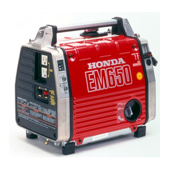
Honda EM650 Owner's Manual
Hide thumbs
Also See for EM650:
- Owner's manual (48 pages) ,
- Owner's manual (18 pages) ,
- Shop manual (59 pages)
Table of Contents
Advertisement
Quick Links
Advertisement
Table of Contents

Related Manuals for Honda EM650


Summary of Contents for Honda EM650
- Page 3 Thank you for purchasing a Honda generator. We want to help you get the best results from your new generator and to operate it safely. This manual contains the information on how to do that; please read it carefully. This owner’s manual describes the operation and maintenance of the EM650 Honda generator.
-
Page 4: Table Of Contents
CONTENTS SAFETY ....................Safety Label Locations ..............4 Safety Information ................COMPONENT IDENTIFICATION ............8 CONTROLS ..................Engine Switch ................Recoil Starter ................Choke Lever ................. Pilot Lamp ..................l 1 Ground Terminal ................Oil Alert System ................AC Circuit Protector ..............DC Terminals ................ - Page 5 MAINTENANCE................. Maintenance Schedule ..............25 Engine Oil Change ................ 26 Air Cleaner Service ...............27 Spark Plug Service ............... 28 Spark Arrester Maintenance ............31 TRANSPORTING/STORAGE ............33 TROUBLESHOOTING ............... 35 WIRNING DIAGRAM ................ .37 SPECIFICATIONS................38 CUSTOMER SERVICE INFORMATION .......... .39 INDEX ....................
-
Page 6: Safety
These labels warn you of potential hazards that can cause serious injury. Read them carefully. Read them carefully. If a label comes off or becomes hard to read, contact your Honda Generator If a label comes off or becomes hard to read, contact your Honda Generator dealer for a replacement. - Page 7 STOP ENGINE BEFORE REFUELING. CHECK SPILLED FUEL OR FUEL LEAKS. ICONTR6LER QU’IL N’Y A NI FUITE NI ESSENCE RtPANOUE L’APPAREIL. AVANT REFAIRE PLEIN: ARRtTER LE MOTEUR. LE PLElN AU OESSUS 0” REPtRE PARA INSPECCIONAR DE NWEA” MAXIMUM. COMBUSTIBLE DERRAMADO ESCAPE ANTES ECHAR ~N~USSTIBLE:...
-
Page 8: Safety Information
SAFETY INFORMATION Honda generators are designed to give safe and dependable service if operated according to instructions. Read and understand this owner’s manual before operating your generator. You can help prevent accidents by being familiar with your generator’s controls, and by observing safe operating procedures. - Page 9 Fire and Burn Hazards The exhaust system gets hot enough to ignite some materials. Keep the generator at least 1 meter (3 feet) away from buildings and other equipment during operation. Do not enclose the generator in any structure. Keep flammable materials away from the generator. The muffler becomes very hot during operation and remains hot for a while after stopping the engine.
-
Page 10: Component Identification
COMPONENT IDENTIFICATION PILOT LAMP CHOKE LEVER ACRECEPTACLES FREQUENCY METER LEFT SIDE COVER OIL FILLER CAP ENGINE SERIAL NUMBER DC TERMINALS FRAME SERIAL NUMBER ClRCUli PROTECTORS GROUND TEdMlNAL Record the engine and frame serial numbers for your future reference. Refer to these serial numbers when ordering parts, and when making technical or warranty inquiries (see page 39) Frame serial number: Engine serial number:... - Page 11 FUEL TANK CAP CARRYING HANDLE RECOIL OUTLET STARTER GRIP SPARK P\LUG COVER AIR CLEANER...
-
Page 12: Controls
CONTROLS Engine Switch To start and stop the engine. Switch position: To stop the engine. OFF: To run the engine. NGINE SWITCH Recoil Starter To start the engine, pull the starter grip lightly until resistance is felt, then pull briskly. Do not allow the starter to snap back against the engine. -
Page 13: Choke Lever
Choke Lever The choke is used to provide an enriched fuel mixture when starting a cold engine. It can be opened and closed by operating the choke lever manually. Move the lever to the CLOSED position to enrich the mixture. CLOSED OPEN CHOKE LEVER... -
Page 14: Ground Terminal
Ground Terminal The generater ground terminal is connected to the frame of the generater, the metal non-current carrying parts of the generator, and the ground terminals of each receptacle. Before using the ground terminal, consult a qualified electrian, electrical inspector or local agency having jurisdiction for local codes or ordinances that apply to the intended use of the generator. -
Page 15: Oil Alert System
Oil Alert System The Oil Alert system is designed to prevent engine damage caused by an insufficient amount of oil in the crankcase. Before the oil level in the crankcase can fall below a safe limit, the Oil Alert system will automatically stop the engine (the engine switch will remain in the ON position). -
Page 16: Dc Terminals
DC Terminals The DC terminals may ONLY be used for charging 12 volt automotive type batteries. The terminals are colored red to identify the positive (+) terminal and black to identify the negative (-) terminal. The battery must be connected to the generator DC terminals with the proper polarity (battery positive to generator red terminal and battery negative to the generator black terminal). -
Page 17: Generator Use
Ground System Honda portable generators have a system ground that connects generator frame components to the ground terminals in the AC output receptacles. The system ground is not connected to the AC neutral wire. If the generator is tested by a receptacle tester, it will not show the same ground circuit condition as for a home receptacle. -
Page 18: Ac Operation
AC Operation 1. Start the engine (refer to page 23) and make sure the pilot lamp comes on. If not, the filament may be burnt out. 2. Plug in the appliance. 1 NOTICE ( Substantial overloading will switch off the circuit protector. Marginal overloading may not switch off the circuit protector, but it will shorten the service life of the generator. -
Page 19: Dc Operation
DC circuit protector (PUSH button extends out). If this happens, wait a few minutes before pushing in the circuit protector to resume operation. If the circuit protector continues to go OFF, discontinue charging and see your authorized Honda generator dealer. -
Page 20: Disconnecting The Battery Cables
Disconnecting the battery cables: 1. Stop the engine. 2. Disconnect the negative (-) battery cable from the generator negative (-) terminal. 3. Disconnect the other end of the negative (-) battery cable from the battery negative (-) terminal. 4. Disconnect the positive (+) battery cable from the generator positive (+) terminal. -
Page 21: High Altitude Operation
If you always operate the engine at altitudes higher than 6,000 feet above sea level, have an authorized Honda generator dealer perform this carburetor modification. Even with suitable carburetor jetting, engine horsepower will decrease ap- proximately 3.5%for each 1,000 foot increase in altitude. -
Page 22: Pre-Operatioin Check
Check the oil level BEFORE EACH USE with the generator on a level sur- face with the engine stopped. Use Honda 4-stroke oil, or an equiva- lent high detergent, premium quality motor oil certified to meet or exceed U.S. automobile manufacturer’s re- TEMP-20 100°F... -
Page 23: Fuel Recommendation
Fuel Recommendation 1. Check the fuel level gauge. 2. Refill the tank if the fuel level is low. Do not fill above the shoulder of the fuel strainer. Gasoline is extremely flammable and is explosive under certain conditions. Refuel in a well-ventilated area with the engine stopped. Do not smoke or allow flames or sparks in the area where the engine is refueled or where gasoline is stored. - Page 24 If spark knock or pinging occurs at a steady engine speed, under normal load, change brands of gasoline. If spark knock or pinging persists, see an authorized Honda generator dealer. [ NOTICE 1 Running the engine with persistent spark knock or pinging can cause engine damage.
- Page 25 Oxygenated Fuels Some conventional gasolines are being blended with alcohol or an ether compound. These gasolines are collectively referred to as oxygenated fuels. To meet clean air standards, some areas of the United States and Canada use oxygenated fuels to help reduce emissions. If you use an oxygenated fuel, be sure it is unleaded and meets the minimum octane rating requirement.
-
Page 26: Starting/Stopping The Engine
STARTING/STOPPING THE ENGINE Starting the engine 1. The generator may be hard to start if a load is connected. 2. Move the choke lever to the CLOSE position. 3. Move the engine switch to the ON position. 4. Pull the starter grip until compression is felt, then pull briskly. NOTICE 1 Do not allow the starter grip to snap back. -
Page 27: Maintenance
If the engine must be run, make sure the area is well ventilated. Use only genuine HONDA parts or their equivalent for main- tenance or repair. Replacement parts which are not of equivalent quality may damage the generator. -
Page 28: Engine Oil Change
Engine Oil Change Drain the oil while the engine is warm to assure complete and rapid draining. 1. Remove the oil filler cap. 2. Turn the engine switch OFF and tilt the generator to drain the oil. 3. Refill with the recommended oil (see page 20 and check the oil level). Oil capacity: 0.35 e (0.37 US qt, 0.31 Imp qt) Please dispose of used motor oil and the oil containers in a manner that is compatible with the environment. -
Page 29: Air Cleaner Service
Air Cleaner Service A dirty air cleaner will restrict air flow to the carburetor. To prevent carburetor malfunction, service the air cleaner regularly. Service more frequently when operating the generator in extremely dusty areas. Using gasoline or flammable solvent to clean the filter element can cause a fire or explosion. -
Page 30: Spark Plug Service
Spark Plug Service Recommended spark plugs: BMR4A (NGK) or W14MR-U (NIPPONDENSO) To ensure proper engine operation, the spark plug must be properly gapped and free of deposits. If the engine has been running, the muffler will be very hot. Be careful not to touch the muffler. - Page 31 4. Visually inspect the spark plug. Discard it if the insulator is cracked or chipped. Clean the spark plug with a wire brush if it is to be reused. 5. Measure the plug gap with a feeler gauge. Correct as necessary by carefully bending the side electrode. The gap should be: 0.6-0.7 mm (0.024-0.028 in) 0.6 - 0.7 mm (0.024-0.028...
- Page 32 7. After the spark plug is seated, tighten with a spark plug wrench to compress the washer. If installing a new spark plug, tighten l/2 turn after the spark plug seats to compress the washer. If reinstalling a used spark plug, tighten 1/8-l /4 turn after the spark plug seats to compress the washer.
-
Page 33: Spark Arrester Maintenance
Spark Arrester Maintenance If the generator has been running, the muffler will be very hot. Allow to cool before proceeding. The spark arrester must be serviced every 100 hours to maintain its efficiency. 1. Remove the fuel tank cap. 2. Remove the four 5 mm pan-screws, and then remove the rear cover. Retighten the fuel tank cap. - Page 34 5. Check for carbon deposits around the exhaust port and the spark arrester. Use a brush to remove carbon deposits from the spark arrester screen. Inspect the spark arrester screen for holes or tears. Replace if necessary. NOTE: The spark arrester must be free of breaks and holes. Replace, if necessary.
-
Page 35: Transporting/Storage
After removal from storage, drain the stored gaso- line into a suitable container, and fill with fresh gasoline before starting. *Use gasoline conditioners that are formulated to extend storage life. Contact your authorized Honda generator dealer for conditioner recom- mendations. - Page 36 1. Drain the carburetor by loosening the drain screw. Drain the gasoline into a suitable container. Gasoline is extremely flammable and is explosive under certain conditions. Perform this task in a well ventilated area with the engine stopped. Do not smoke or allow flames or sparks in the area during this procedure.
-
Page 37: Troubleshooting
4) Pull the recoil starter, sparksshouldjumpacross the gap. 1) Turn off the engine switch loosen drain 2) Fuel should flow from the start, take the generator drain when the engine to an authorized HONDA switch is turned on. - Page 38 Push the AC circuit pro- Is the AC circuit protec- tor on? tector button in. Check the electrical ap- Take the generator NO DEFECTS pliance or equipment for w an authorized HONDA any defects dealer. Replace the electrical appliance or equip- ment. DEFECTS Take...
-
Page 39: Wirning Diagram
WIRING DIAGRAM... -
Page 40: Specifications
SPECIFICATBONS Dimension 1 EA3 Power product description code 41Ox270x375mm Length x Width x Height (16.1 x 10.6 x 14.8 in) 1 22 kg (48.5 ib) Dry Weight Engine 4-stroke, side valve, 1 cylinder Engine Type 76 cc (4.65 cu in) Displacement (46 x 46 mm (1.81 x 1.81 in)] [Bore x Stroke]... -
Page 41: Customer Service Information
Manager can help. Almost all problems are solved in this way. If you are dissatisfied with the decision made by the dealership’s manage- ment, contact the Honda Power Equipment Customer Service Office. You can writ0 to: American Honda Motor Co.,lnc. - Page 42 When you write or call, please provide the following information: • Model and serial numbers • Name of the dealer who sold the Honda power equipment to you • Name and address of the dealer who services your equipment •...
-
Page 43: Index
INDEX COMPONENT IDENTIFICATION ............8 CONTROLS ..................AC Circuit Protector..............13 Choke Lever ................. DC Circuit Protector..............14 DC Terminals ................Engine Switch ................Ground Terminal................Oil Alert System ................Pilot Lamp ..................Recoil Starter ................CUSTOMER SERVICE INFORMATION .......... .39 GENERATOR USE.. -
Page 44: Pre-Operation Check
INDEX PRE-OPERATION CHECK ............... 20 Engine Oil ..................Fuel Recommendation ..............21 SAFETY ....................Safety Information ................Safety Label Locations ..............4 SPECIFICATIONS ................STARTING/STOPPING THE ENGINE ..........24 TRANSPORTING/STORAGE ............33 TROUBLESHOOTING ............... 35 WIRING DIAGRAM................37... - Page 45 MEMO...
- Page 46 MEMO...
- Page 47 MEMO...