Table of Contents
Advertisement
Advertisement
Table of Contents

Related Manuals for Honda EX650


Summary of Contents for Honda EX650
- Page 2 The generator is a potential source of electrical shock if misused. not expose the generator to moisture, rain or snow. Do not let the generator get wet, and do not operate it with wet hands. The engine exhaust from this product contains chemicals known to the State of California to cause cancer, birth defects or other reproductive harm.
- Page 3 This owner’s manual describes the operation and maintenance of the EX650 Honda Generator. All information in this publication is based on the latest product information available at the time of printing. Honda Motor Co,. Ltd.
-
Page 4: Table Of Contents
CONTENS SAFETY ....................Safety Label Locations ..............4 Safety Information ................5 COMPONENT IDENTIFICATION ............7 CONTROLS ..................Engine Switch ................. Recoil Starter.................. Choke ..................... Pilot Lamp ..................Ground Terminal ................Oil Alert System................1 1 AC Circuit Protector...............l 1 DC Terminals ................ - Page 5 PRE-OPERATION CHECK ..............18 Engine Oil ..................Fuel Recommendation ..............19 STARTING/STOPPING THE ENGINE ..........21 MAINTENANCE .................22 Maintenance Schedule ..............22 Tool Kit ..................Engine Oil Change ............... .24 Air Cleaner Service ...............25 Spark Plug Service ............... .26 Spark Arrester Maintenance ............
-
Page 6: Safety
SAFETY SAFETY LABEL LOCATION These labels warn you of potential hazards that can cause serious injury. Read them carefully. If a label comes off or becomes hard to read, contact your Honda Generator dealer for a replacement. EXHAUST OUTLET CAUTION... -
Page 7: Safety Information
SAFETY INFORMATION Honda generators are designed to give safe and dependable service if operated according to instructions. Read and understand this owner’s manual before operating your generator. You can help prevent accidents by being familiar with your generator’s controls, and by observing safe operating... - Page 8 Fire and Burn Hazards The exhaust system gets hot enough to ignite some materials. Keep the generator at least 1 meter (3 feet) away from buildings and other equipment during operation. Do not enclose the generator in any structure. Keep flammable materials away from the generator. The muffler becomes very hot during operation and remains hot for a while after stopping the engine.
-
Page 9: Component Identification
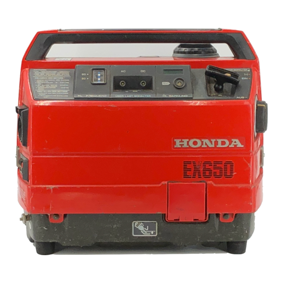
COMPONENT IDENTIFICATION CARRYING HANDLE FREQUENCY METER PILOT LAMP AC CIRCUIT PROTECTOR STARTER GRIP DC CIRCUIT ’ PROTECTOR ENGINE SERIAL NUMBER ENGINE FILLER SWITCH CAP COVER Record the engine serial number for your future reference. Refer to this serial number when ordering parts, and when making technical or warranty inquiries (see page 37) Engine serial number:... - Page 10 FUEL TANK FUEL GAUGE CEPTACLE DC TERMINALS ‘GROUND TERMINAL EXHAUST OUTLET...
-
Page 11: Controls
CONTROLS Engine Switch To start and stop the engine. Switch position: OFF: To stop the engine. To run the engine. (Restart “HOT” engine) CHOKE: To start the engine. (“Cold” engine) HOKE ENGINE SWITCH Recoil Starter To start the engine, pull the starter grip lightly until resistance is felt, then pull briskly. -
Page 12: Pilot Lamp
Pilot Lamp The pilot lamp is illuminated when the generator is operating normally. It indicates that the generator is producing electrical power. If the pilot light is illuminated, the frequency meter should be displaying 60 Hz. FREQUENCY METER LAMP PILOT Ground Terminal The gernerator ground terminal is connected to the frame of the generater, the metal non-current carrying parts of the generator, and the ground terminals of... -
Page 13: Oil Alert System
Oil Alert System The Oil Alert system is designed to prevent engine damage caused by an insufficient amount of oil in the crankcase. Before the oil level in the crankcase can fall below a safe limit, the Oil Alert system will automatically stop the engine (the engine switch will remain in the ON position). -
Page 14: Dc Terminals
DC Terminals The DC terminals may ONLY be used for charging 12 volt automotive type batteries. The terminals are colored red to identify the positive (+) terminal and black to identify the negative (-) terminal. The battery must be connected to the generator DC terminals with the proper polarity (battery positive to generator red terminal and battery negative to the generator black terminal). -
Page 15: Generator Use
Ground System Honda portable generators have a system ground that connects generator frame components to the ground terminals in the AC output receptacles. The system ground is not connected to the AC neutral wire. If the generator is tested by a receptacle tester, it will not show the same ground circuit condition as for a home receptacle. -
Page 16: Ac Operation
AC Operation 1. Start the engine (refer to page 22) and make sure the pilot lamp comes on. If not, the filament may be burnt out. 2. Plug in the appliance. 1 NOTICE 1 Substantial overloading will switch off the circuit protector, Marginal overloading may not switch off the circuit protector, but it will shorten the service life of the generator. -
Page 17: Dc Operation
DC circuit protector (PUSH button extends out). If this happens, wait a few minutes before pushing in the circuit protector to resume operation. If the circuit protector continues to go OFF, discontinue charging and see your authorized Honda generator dealer. -
Page 18: Disconnecting The Battery Cables
Disconnecting the battery cables: 1. Stop the engine. 2. Disconnect the negative (-) battery cable from the generator negative (-) terminal. 3. Disconnect the other end of the negative (-) battery cable from the battery negative (-) terminal. 4. Disconnect the positive (+) battery cable from the generator positive (+) terminal. -
Page 19: High Altitude Operation
If you always operate the engine at altitudes higher than 6,000 feet above sea level, have an authorized Honda generator dealer perform this carburetor modification. Even with suitable carburetor jetting, engine horsepower will decrease ap- proximately 35%for each 1,000 foot increase in altitude. -
Page 20: Pre-Operation Check
Check the oil level BEFORE EACH USE with the generator on a level sur- face with the engine stopped. Use Honda 4-stroke oil, or an equivalent high detergent, premium quality motor oil certified to meet or exceed U.S. auto- mobile manufacturer’s requirements for Service Classification SG, SF/CC, CD. -
Page 21: Fuel Recommendation
Fuel Recommendation 1. Check the fuel level gauge. 2. Refill the tank if the fuel level is low. Do not fill above the shoulder of the fuel strainer. Gasoline is extremely flammable and is explosive under certain conditions. Refuel in a well-ventilated area with the engine stopped. - Page 22 If you notice any undesirable operating symptoms, switch to a conventional unleaded gasoline. Fuel system damage or performance problems resulting from the use of an oxygenated fuel are not the responsibility of Honda and are not covered under warranty.
-
Page 23: Starting/Stopping The Engine
STARTING/STOPPING THE ENGINE Starting the engine 1. The generator may be hard to start if a load is connected. 2. Turn the engine switch to the CHOKE position (“Cold” engine), or Turn the engine switch to the ON position (restart “Hot” engine). 3. -
Page 24: Maintenance
If the engine must be run, make sure the area is well ventilated. pi6eq Use only genuine HONDA parts or their equivalent maintenance or repair. Replacement parts which are not of equivalent quality may damage the generator. MAINTENANCE SCHEDULE... -
Page 25: Tool Kit
Engine Oil Change Drain the oil while the engine is warm to assure complete and rapid draining. 1. Remove the oil filler cap cover and filler cap. 2. Turn the engine switch OFF and tilt the generator to drain the oil. 3. -
Page 26: Engine Oil Change
Air Cleaner Service A dirty air cleaner will restrict air flow to the carburetor. To prevent carburetor malfunction, service the air cleaner regularly. Service more frequently when operating the generator in extremely dusty areas. Using gasoline or flammable solvent to clean the filter element can cause a fire or explosion. -
Page 27: Air Cleaner Service
LAiCH AIR CLEANER ELEMENT COVER SPRING... -
Page 28: Spark Plug Service
Spark Plug Service Recommended spark plug: BMR4A (NGK) To ensure proper engine operation, the spark plug must be properly gapped and free of deposits. If the engine has been running, the muffler will be very hot. Be careful not to touch the muffler. - Page 29 6. Check that the spark plug washer is in good condition, and thread the spark plug in by hand to prevent cross-threading. 7. After the spark plug is seated, tighten with a spark plug wrench to compress the washer. If installing a new spark plug, tighten l/2 turn after the spark plug seats to compress the washer.
-
Page 30: Spark Arrester Maintenance
Spark Arrester Maintenance If the generator has been running, the muffler will be very hot. Allow to cool before proceeding. The spark arrester must be serviced every 100 hours to maintain its efficiency. 1. Unfasten the two latches and remove the rear cover. 2. - Page 31 5. Check for carbon deposits around the exhaust port and the spark arrester. Use a brush to remove carbon deposits from the spark arrester screen. Inspect the spark arrester screen for holes or tears. Replace if necessary. NOTE: The spark arrester must be free of breaks and holes. Replace, if necessary.
-
Page 32: Transporting/Storage
Change the engine oil (page 24). After removal from storage, drain the stored gasoline into a suitable container, and fill with fresh gasoline before starting. * Use gasoline conditioners that are formulated to extend storage life. Contact your authorized Honda generator dealer for conditioner recommendations. - Page 33 1. Drain the carburetor by loosening the drain screw. Drain the gasoline into a suitable container. Gasoline is extremely flammable and is explosive under certain condi- tions. Perform this task in a well ventilated area with the engine stopped. Do not smoke or allow flames or sparks in the area during this proce- dure.
-
Page 34: Troubleshooting
Is there a spark at Replace the the spark plug? spark plug ’ tor to an autho- rized HONDA To check: dealer. 1) Remove the rear cover and Be sure there is no spark plug cap, and clean spilled fuel around the any dirt from around the spark plug. - Page 35 No electricity at the AC receptacles: Push the AC circuit Is the AC circuit protector on? protector button in. NO DEFECTS Take the generator to Check the electrical an authorized HONDA appliance or dealer. equipment for any defects equipment. DEFECTS Take the electrical...
-
Page 37: Specifications
SPECIFICATIONS Dimensions 430 x 270 x 375 mm Length x Width x Height (16.9 x 10.6 x 14.8 in) 23 kg (50.72 lb). Dry Weight Engine Engine Type 4-stroke, side valve, 1 cylinder Displacement 76 cc (4.65 cu in) [46 x 46 mm (1.81 x 1.81 in)] [Bore x Stroke] Compression Ratio... -
Page 38: Customer Service Information
Manager can help. Almost all problems are solved in this way. If you are dissatisfied with the decision made by the dealership’s manage- ment, contact the Honda Power Equipment Customer Service Office. You can write to: American Honda Motor Co., Inc. - Page 39 When you write or call, please provide the following information: • Model and serial numbers • Name of the dealer who sold the Honda power equipment to you • Name and address of the dealer who services your equipment •...
-
Page 40: Index
INDEX COMPONENT IDENTIFICATION ............7 CONTROLS ................... AC Circuit Protector................Choke ....................DC Circuit Protector ................. 12 DC Terminals ................... Engine Switch ..................Ground Terminal ................Oil Alert System ................Pilot Lamp ..................Recoil Starter ..................CUSTOMER SERVICE INFORMATION ..........36 GENERATOR USE ................ -
Page 41: Wiring Diagram
INDEX MAINTENANCE .................. Air Cleaner Service ................25 Engine Oil Change ................24 Maintenance Schedule ..............22 Spark Arrester Maintenance.............28 Spark Plug Service ................26 Tool Kit .................... PRE-OPERATION CHECK ..............18 Engine Oil ..................Fuel Recommendation ..............19 SAFETY .................... - Page 42 MEMO...
- Page 43 MEMO...