Advertisement
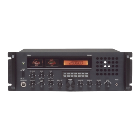
DX 2527
SWR
RX / TX
9
WATTS
SIGNAL
POWER
ON
RF POWER
ECHO
TIME
N B/ANL
R .BEEP
SPLIT
D IM
SWR
SCAN
OFF
MIN
MAX
MIN
MAX
OFF
CHANNEL
MICROPHONE
CALIBRATE
TONE
TALK BACK
MIC
RF
R OBOT
VOICE
R2
ECHO
R3
R4
RF
OFF
·
·
AM
FM
SSB
Amateur Base Station Transceiver
OWNER'S MANUAL
2527
PRG
MAN
SHF
MEM
ENT
LOCK
CLARIFIER
SQUELCH
VOLUME
MODE
PHONE
U SB
LSB
AM
CW
FM
PA
·
·
CW
PA
TABLE OF CONTENTS
SPECIFICATIONS .............................................................
INSTALLATION ................................................................
Introduction ....................................................................
Control & Connections ..........................................
Rear Panel Connectors ..........................................
Microphone .........................................................
Operation ............................................................
Programming. ......................................................
- 1 -
2
3
6
6
10
11
11
12
Advertisement
Table of Contents

Related Manuals for Galaxy DX 2527


Summary of Contents for Galaxy DX 2527
-
Page 1: Table Of Contents
TABLE OF CONTENTS SPECIFICATIONS ............. DX 2527 INSTALLATION ..............OPERATION Introduction ..............Control & Connections …………………………………… Rear Panel Connectors …………………………………... 2527 RX / TX Microphone ………………………………………………… WATTS SIGNAL POWER RF POWER ECHO TIME N B/ANL R .BEEP SPLIT D IM SCAN LOCK Operation …………………………………………………... -
Page 2: Specifications
SPECIFICATION: INSTALLATION: Location/Connection GENERAL The transceiver should be placed in a convenient operating location Frequency Range 28.0000 – 29.6999 MHz close to an AC power outlet and the antenna lead in cable(s). Emission Types CW, FM, AM, USB, LSB The transceiver is powered with the AC power cord set. Proceed as Frequency Control Phase-Lock-Loop Synthesizer Frequency Tolerance... -
Page 3: Public Address
Antennas Public address Antennas are purchased separately and include installation An external 8 ohms, 3-Watt speaker must be connected to the PA instructions. Numerous type of antennas are available that range from jack located on the rear panel when the transceiver is used as a public emphasis on easy of installation to emphasis on performance. -
Page 4: Operation
OPERATION: mark.) Then, while still transmitting, push the small white SWR switch (number 11). This will give you an SWR reading. When you are finished, be sure to turn the calibrate control. Fully CCW to the “RF” position so you are able to read your RF output power. - Page 5 10. MIC GAIN CONTROL: This control adjusts the microphone 18 VOLUME: Permits you to adjust the listening level when gain in the transmit mode. This feature is designed for use in a receiving. high-ambient noise environment or to maximize talk power. 19.
-
Page 6: Rear Panel Connectors
29. PROGRAM SWITCH: This switch is used to program 3. EXTERNAL SPEAKER: This jack accepts 4 to 8 ohms, 5-watt operating or scanning frequency into memory. external speaker. When the external speaker is connected to this jack, the built-in speaker will be disabled. 30. -
Page 7: Programming
OPERATION PROCEDURE 2. The second method of frequency selection is accomplished using the SHF button and the channel select knob located on Frequency Selection the front panel. Use the SHF button in the manner described Frequency selection for the DX 2527 is simple. Select the desired above to select the digit to be changed. - Page 8 or turn the Squelch control counterclockwise until you hear the 2. Press the MEM button. receiver noise. The MAN button will disable the Scan function. 3. Slowly turn the Squelch knob clockwise until the receiver (See Frequency Scanning for more information.) noise disappears.
- Page 9 2. Press the MEM button. "PRG" should be display in the 1. Press the PRG (Program) button. lower right-hand corner of the LCD display window. In the 2. Press the SCAN button. ("PRG SCAN+" should appear in upper left portion of the display, "MEM" should be the lower right corner of the display window.) displayed.
- Page 10 We will repair and return your radio as soon as we can. We appreciate your choosing a either "SPLIT+" or "SPLIT-" will be displayed. If Galaxy radio and we want you to be on the air as much as possible! "SPLIT+" is displayed, the transmitter will be offset 100 Be sure to visit our web site at KHz above the receive frequency when keyed.