Fluke 574 User Manual
Precision infrared thermometer
Hide thumbs
Also See for 574:
- Brochure & specs (12 pages) ,
- Technical data (4 pages) ,
- Getting started (28 pages)

Related Manuals for Fluke 574


Summary of Contents for Fluke 574
- Page 1 Precision Infrared Thermometer Users Manual March 2005 © 2005 Fluke Corporation. All rights reserved. All product names are trademarks of their respective companies.
- Page 2 LIMITED WARRANTY AND LIMITATION OF LIABILITY This Fluke product will be free from defects in material and workmanship for one year from the date of purchase. This warranty does not cover fuses, disposable batteries, or damage from accident, neglect, misuse, alteration, contami- nation, or abnormal conditions of operation or handling.
-
Page 3: Safety Information
Safety Information Warning A Warning identifies conditions and actions that pose ha- zards to the user. To avoid electrical shock or personal injury, follow these guidelines: • Do not point laser directly at eye or indirectly off reflective surfaces. • Before using the thermometer inspect the case. Do not use the thermometer if it appears damaged. -
Page 4: Table Of Contents
Table of Contents Introduction ............5 Warning for the Model 574 NI ....... 6 Symbols and Safety Markings ......7 Laser Warning and Serial Number Labels..... 8 Delivery Content............ 9 Functions and Display........... 10 Batteries and Measurement ........11 Field of View ............12 Spot Size ............... -
Page 5: Introduction
This thermometer determines an object‘s surface temperature by measuring the amount of infrared energy radiated by the object‘s surface. Contacting Fluke To contact Fluke, call one of the following telephone numbers: USA: 1-888-44-FLUKE (1-888-443-5853) Canada: 1-800-36-FLUKE (1-800-363-5853) Europe: +31 402-675-200... -
Page 6: Warning For The Model 574 Ni
IN HAZARDOUS LOCATIONS DO NOT use serial port con- nections, change batteries or open serial port cover. To re- duce risk of explosion in hazardous locations, use only Fluke temp probe part 2432508 and do not use other accessories, such as power supply and cables. -
Page 7: Symbols And Safety Markings
Symbols and Safety Markings Symbol Explanation Risk of danger. Important information. See Risk of danger. Important information. See Risk of danger. Important information. See Manual. Manual. Hazardous voltage. Precedes warning Warning. Laser. Conforms to requirements of European Union Conforms to requirements of European Union Conforms to requirements of European Union ... -
Page 8: Laser Warning And Serial Number Labels
Laser Warning and Serial Number Labels... -
Page 9: Delivery Content
Delivery Content • The unit • Getting Started • Two AA batteries • Manual on CD • Thermocouple type K probe • Windows-based software on CD • RS232 cable • Power supply... -
Page 10: Functions And Display
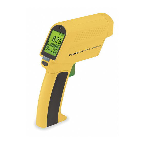
Functions and Display FUNCTIONS USER INTERFACE Function keys and display: (A) Visual and audible alarm (B) Display (C) Up and Down keys (D) Enter (E) Handle and battery compartment (DIP switches for adjustments are inside handle) (F) Trigger (G) Tripod mount (H) 6 main function keys DISPLAY Displayed functions:... -
Page 11: Batteries And Measurement
Batteries and Measurement To open the battery compartment, press gently on the top part of the handle to release the catch and pivot the grip as shown in the figure. Orient the batteries (two alkaline R6 (AA, UM3)) positive side up as shown on the housing. -
Page 12: Field Of View
Field of View Make sure that the target is larger than the unit’s spot size. The smaller the target, the closer you should be to it. -
Page 13: Spot Size
Spot Size STANDARD MODEL Optical Chart DISTANCE: SENSOR TO OBJECT (IN) 0.76 IN @ 46 IN 1.85 1.51 0.82 0.87 0.81 19.8 29.0 44.0 58.0 19 mm @ 1150 mm 72.0 DISTANCE: SENSOR TO OBJECT (mm) FOCUS POINT D:S = 60:1 FAR FIELD D:S = 35:1 CLOSE FOCUS MODEL Optical Chart... -
Page 14: Emissivity - Explanation And Adjust
Emissivity - Explanation and Adjust The amount of infrared energy radiated by an object depends on its emissivity and its Reflected energy temperature. Emitted energy The emissivity depends on the material and its surface characteristics. For more EMISSIVITY Transmitted energy accurate readings, adjust Target the emissivity value for... -
Page 15: Emissivity - Table And Unknown Value
Emissivity - Table and Unknown Value TABLE OF VALUES TABLE OF VALUES To choose the emissivity of a material, press EMISS (P). The display shows a material name (7), an emissivity value, and the calculated temperature value (5). To choose another material, use the Up and Down keys (C). -
Page 16: Mode - Maximum And Minimum
Mode - Maximum and Minimum MAXIMUM To activate the MAX mode, press MODE (O) until the MAX symbol appears (9). The measured maximum temperature is displayed (3) as long as the trigger is pulled or locked on. The real time temperature is shown in the lower part of the display (NORM) (7). -
Page 17: Mode - Difference And Avarage
Mode - Difference and Avarage DIFFERENCE To activate the DIF mode, press MODE (O) until the DIF symbol (9) appears. The difference between the measured max and min temperatures is displayed (3) as long as the trigger is pulled or locked on. -
Page 18: Probe Connections
Probe Connections PROBE CONNECTIONS Open the battery compart- ment and set the switches ON or Off according to the desired probe type. (10) NTC - thermistor (11) TC - thermocouple (12) Thermocouple type J (13) Thermocouple type K Connect the probe to the input (U). -
Page 19: Setup Alarm
Setup Alarm HIGH ALARM The high alarm (HiAl) generates an audible and visual (flashing LED (A) and laser) alarm if the temperature is above the setpoint. To set the alarm value (6), Press SETUP (N) once, and use the Up and Down keys (C). -
Page 20: Setup - Time And Date
Setup - Time and Date TIME To set the time, press SETUP (N) three times. Change the time (2) using the Up and Down keys (C). Then press ENTER (D) for each time segment to activate this time setting. The time appears on the display and is stored within the data logger. -
Page 21: Setup - Offset And Min-Max Values
Setup - Offset and Min-Max Values OFFSET This function is used with a selected emissivity to add or subtract an offset value (±10°C/±18°F) to the temperature value. Press the Setup button (N) until "Offset" appears in the display. With the arrow keys (C) adjust the display to the corrected value. -
Page 22: Data Logging And Recall
Data Logging and Recall HOW TO STORE DATA By pressing the ENTER button (D) the LOG function (6) appears on the display. Pull the trigger (F) and hold it. Aim at the target. Be sure that the laser sighting is inside the target. -
Page 23: Display
Display GRAPHIC DISPLAY The graphic display (4) shows the temperature as a picture. The last ten measurements are shown (B). It is possible to choose between Auto Range and Manual Range. In manual range the user defines the beginning and ending temperature points of the graph. -
Page 24: Display - Man. Range
Display - Man. Range DISPLAY BEGIN (Man. Range) To set the BEGIN value for the graphic display (Man Range is activated), press DISPLAY (L) until “Begin” is shown at the status bar. Use the Up and Down keys (C) to select the value (6). -
Page 25: Display - Cycle
Display - Cycle CYCLE allows the adjustment of the display interval. Press DISPLAY (L) until Cycl.: (7) is shown at the status bar. To select the interval time, use the Up and Down keys (C). The default value is pre-set for 0.2 sec. -
Page 26: Dip Switches
DIP Switches Change the setting in the Factory Defaults DIP-Switch Settings unit by using the DIP switches located in the battery compartment (see Lock BATTERIES section). BATTERIES section). C/ F Buzzer Lock: Trigger locked Backlight (on) or Set Default unlocked (off). °C/°F: °C/°F: changes between... -
Page 27: Troubleshooting
Troubleshooting Code Problem Action Target temp. is over Select target or under range within unit’s specs EEPROM-Err EEPROM error Contact factory CalAreaErr Calibration errors Contact factory ProbCalErr Battery icon Battery is low Replace batteries flashes or LowBatt on Status line Blank display Battery is dead Replace batteries... -
Page 28: Maintenance
Maintenance Lens Cleaning: Blow off loose particles using clean compressed air. Brush remaining de- bris away with a camel’s hair brush. Wipe the surface with a moist cotton swab. The swab may be moistened with water or a water based glass cleaner. NOTE: DO NOT use sol- vents to clean the plastic lens. -
Page 29: Emissivity Table (Selected Values)
Emissivity Table (Selected Values) Aluminum* 0.30 Asbesto 0.95 Asphalt 0.95 Basalt 0.70 Brass* 0.50 Brick 0.90 Carbon 0.85 Ceramic 0.95 Concrete 0.95 Copper* 0.95 Dirt 0.94 Frozen food, 0.90 Hot food 0.93 Glass (plate) 0.85 0.98 Iron* 0.70 Lead* 0.50 Limestone 0.98 0.94... -
Page 30: Ce Conformity
CE Conformity This instrument conforms to the following standards: EMC: - EN 61326-1:1997+A1:1998+A2:2001 Safety: - EN 61010-1:2001 - EN 60825-1:2001 This product herewith complies with the requirements of the EMC Directive 89/336/EEC and the Low Voltage Directive 73/23/EEC. This instrument conforms to the Standards of the European Community. -
Page 31: Specifications
Specifications Temperature Range - 30 to 900°C (- 25 to 1600°F) Display Resolution 0.1°C (0.2°F) Accuracy ± 0.75% of reading or (Infrared) ± 0.75K (± 1,5°F), whichever is greater at 25°C (77°F) ambient temperature, ± 2K (± 4°F) for targets below -5°C (23°F) Ambient derating <... -
Page 32: Factory Defaults
Power 2 x 1.5 V Alkaline Type AA Battery Life 13 hrs. (50% laser and 50% backlight on) 7.5 V > 200 mA (Using the power supply Power supply (External) the display automatically switches on) Dimensions 200 x 170 x 50 mm (7.9 x 6.7 x 2 inches) Tripod Mount 1/4”-20 UNC Factory Defaults...