Asus P5WD2 Premium User Manual
Hide thumbs
Also See for P5WD2 Premium:
- User manual (60 pages) ,
- Installation manual (150 pages) ,
- Installation manual (164 pages)
Table of Contents
Advertisement
Quick Links
Advertisement
Table of Contents

Related Manuals for Asus P5WD2 Premium


Summary of Contents for Asus P5WD2 Premium
- Page 1 P5WD2 Premium...
- Page 2 Product warranty or service will not be extended if: (1) the product is repaired, modified or altered, unless such repair, modification of alteration is authorized in writing by ASUS; or (2) the serial number of the product is defaced or missing.
-
Page 3: Table Of Contents
Welcome! ................1-1 Package contents ..............1-1 Special features ..............1-2 1.3.1 Product highlights ........... 1-2 1.3.2 ASUS AI Life features ..........1-6 1.3.3 Innovative ASUS features ........1-7 Chapter 2: Hardware information Chapter 2: Hardware information Chapter 2: Hardware information... - Page 4 Managing and updating your BIOS ........4-1 4.1.1 Creating a bootable floppy disk ......4-1 4.1.2 AFUDOS utility ............4-2 4.1.3 ASUS CrashFree BIOS 2 utility ........ 4-5 4.1.4 ASUS EZ Flash utility ..........4-7 4.1.5 ASUS Update utility ..........4-8 BIOS setup program ............4-11 4.2.1...
- Page 5 Manuals menu ............5-5 5.2.6 Contact information ..........5-6 5.2.7 Other information ........... 5-6 Software information ............5-8 5.3.1 ASUS MyLogo2™ ............ 5-8 5.3.2 AI NET2 ..............5-10 5.3.3 Audio configurations ..........5-11 RAID configurations ............5-17 5.4.1 Installing Serial ATA hard disks ......5-18 5.4.2...
-
Page 6: Notices
Notices Federal Communications Commission Statement Federal Communications Commission Statement Federal Communications Commission Statement Federal Communications Commission Statement Federal Communications Commission Statement This device complies with Part 15 of the FCC Rules. Operation is subject to the following two conditions: • This device may not cause harmful interference, and •... -
Page 7: Safety Information
Safety information Electrical safety Electrical safety Electrical safety Electrical safety Electrical safety • To prevent electrical shock hazard, disconnect the power cable from the electrical outlet before relocating the system. • When adding or removing devices to or from the system, ensure that the power cables for the devices are unplugged before the signal cables are connected. -
Page 8: About This Guide
A S U S w e b s i t e s A S U S w e b s i t e s The ASUS website provides updated information on ASUS hardware and software products. Refer to the ASUS contact information. - Page 9 Conventions used in this guide Conventions used in this guide Conventions used in this guide Conventions used in this guide Conventions used in this guide To make sure that you perform certain tasks properly, take note of the following symbols used throughout this manual. D A N G E R / W A R N I N G : D A N G E R / W A R N I N G : D A N G E R / W A R N I N G :...
-
Page 10: P5Wd2 Premium Specifications Summary
P5WD2 Premium specifications summary C P U C P U C P U C P U C P U LGA775 socket for Intel ® Pentium ® 4/Celeron processor Compatible with Intel ® PCG 05B/05A and 04B/04A processors Supports Intel ® Enhanced Memory 64Technology (EM64T) Supports Enhanced Intel SpeedStep ®... - Page 11 100 MHz up to 450 MHz at 1 MHz increment - PCI Express x16 Frequency from 90 MHz up to 150 MHz at 1 MHz increment ASUS AI Overclocking (intelligent CPU tuner) Adjustable FSB/DDR2 frequencies with fixed PCI/PCI Express frequencies ASUS Ai Booster utility ASUS C.P.R.
- Page 12 1 x IEEE 1394a port connector 1 x GAME/MIDI connector 1 x Serial port connector ATX power connectors (24-pin and 2 x 4-pin) ASUS EZ Plug™ connector 2 x Chassis fan connectors CPU fan connector Power fan connector Chassis intrusion connector...
-
Page 13: Chapter 1: Product Introduction
This chapter describes the motherboard features and the new technologies it supports. Product introduction... -
Page 14: Chapter Summary
Chapter summary Welcome! ................1-1 Package contents ..............1-1 Special features ..............1-2 A S U S P 5 W D 2 P r e m i u m A S U S P 5 W D 2 P r e m i u m A S U S P 5 W D 2 P r e m i u m A S U S P 5 W D 2 P r e m i u m A S U S P 5 W D 2 P r e m i u m... -
Page 15: Welcome
The motherboard delivers a host of new features and latest technologies, making it another standout in the long line of ASUS quality motherboards! Before you start installing the motherboard, and hardware devices on it, check the items in your package with the list below. -
Page 16: Special Features
Special features 1.3.1 1.3.1 1.3.1 1.3.1 1.3.1 Product highlights Product highlights Product highlights Product highlights Product highlights Latest processor technology Latest processor technology Latest processor technology Latest processor technology Latest processor technology The motherboard comes with a 775-pin surface mount Land Grid Array (LGA) socket designed for the Intel ®... - Page 17 Enhanced Intel SpeedStep Enhanced Intel SpeedStep Technology (EIST) Technology (EIST) Enhanced Intel SpeedStep Enhanced Intel SpeedStep Enhanced Intel SpeedStep ® Technology (EIST) Technology (EIST) Technology (EIST) The Enhanced Intel SpeedStep ® Technology (EIST) intelligently manages the CPU resources by automatically adjusting the CPU voltage and core frequency depending on the CPU loading and system speed or power requirement.
- Page 18 8-channel high definition audio 8-channel high definition audio 8-channel high definition audio 8-channel high definition audio 8-channel high definition audio Onboard is the Realtek ® ALC882D High Definition Audio 8-channel audio CODEC. This CODEC is fully-compliant with Intel ® High Definition Audio standard (192 KHz, 24-bit audio).
- Page 19 USB 2.0 technology USB 2.0 technology USB 2.0 technology USB 2.0 technology USB 2.0 technology The motherboard implements the Universal Serial Bus (USB) 2.0 specification, dramatically increasing the connection speed from the 12 Mbps bandwidth on USB 1.1 to a fast 480 Mbps on USB 2.0. USB 2.0 is backward compatible with USB 1.1.
-
Page 20: Asus Ai Life Features
You can share photos, videos, and MP3 files with other wireless devices without tangling cables and wires. The ASUS WiFi-TV card also offers digital TV (for DVB-T only) connection, which presents higher TV resolution and more functions compared to the traditional analog TV standard. -
Page 21: Innovative Asus Features
ASUS Stack Cool 2 ASUS Stack Cool 2 ASUS Stack Cool 2 is a fan-less and zero-noise cooling solution that lowers the temperature of critical heat generating components by 20ºC. The motherboard uses a special design on the printed circuit board (PCB) to dissipate heat that critical components generate. - Page 22 ASUS EZ Plug™ ASUS EZ Plug™ ASUS EZ Plug™ This patented ASUS technology is a 4-pin auxiliary +12V connector that is designed to maintain the voltage integrity of your system. This plug guarantees adequate supply of power to the motherboard and other installed peripherals.
- Page 23 ASUS Q-Fan 2 technology ASUS Q-Fan 2 technology ASUS Q-Fan 2 technology The ASUS Q-Fan 2 technology smartly adjusts the fan speeds according to the system loading to ensure quiet, cool, and efficient operation. See pages 4-37 to 4-38 for details.
- Page 24 1 - 1 0 1 - 1 0 C h a p t e r 1 : P r o d u c t i n t r o d u c t i o n C h a p t e r 1 : P r o d u c t i n t r o d u c t i o n 1 - 1 0 1 - 1 0 1 - 1 0...
-
Page 25: Chapter 2: Hardware Information
This chapter lists the hardware setup procedures that you have to perform when installing system components. It includes description of the jumpers and Hardware connectors on the motherboard. information... - Page 26 Chapter summary Before you proceed .............. 2-1 Motherboard overview ............2-2 Central Processing Unit (CPU) ..........2-7 System memory ..............2-14 Expansion slots ..............2-20 Jumper ................2-26 Connectors ................. 2-27 A S U S P 5 W D 2 P r e m i u m A S U S P 5 W D 2 P r e m i u m A S U S P 5 W D 2 P r e m i u m A S U S P 5 W D 2 P r e m i u m...
-
Page 27: Before You Proceed
Before you proceed Take note of the following precautions before you install motherboard components or change any motherboard settings. • Unplug the power cord from the wall socket before touching any component. • Use a grounded wrist strap or touch a safely grounded object or a metal object, such as the power supply case, before handling components to avoid damaging them due to static electricity. -
Page 28: Motherboard Overview
Motherboard overview Before you install the motherboard, study the configuration of your chassis to ensure that the motherboard fits into it. Make sure to unplug the power cord before installing or removing the motherboard. Failure to do so can cause you physical injury and damage motherboard components. -
Page 29: Asus Stack Cool 2
ASUS Stack Cool 2 ASUS Stack Cool 2 The motherboard comes with the ASUS Stack Cool 2 cooling solution that lowers the temperature of critical heat generating components by 20ºC. The motherboard uses a special design on the printed circuit board (PCB) to dissipate heat that critical components generate. -
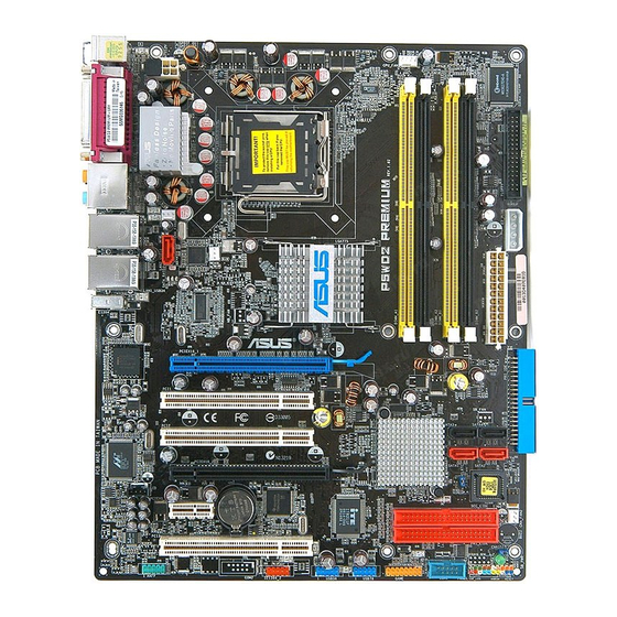
Page 30: Motherboard Layout
2.2.4 2.2.4 2.2.4 Motherboard layout Motherboard layout Motherboard layout 2.2.4 2.2.4 Motherboard layout Motherboard layout 24.5cm (9.6in) PS/2KBMS T: Mouse B: Keyboard CPU_FAN EATX12V SPDIF_O SPDIF_O2 LGA775 AUDIO CHA_FAN1 LAN2_USB12 SATA Link PWR_FAN ® LAN1_USB34 Intel MCH 955X IE1394a ® Gbit PCIEX16_1 PCI1... -
Page 31: Layout Contents
2.2.5 2.2.5 2.2.5 Layout contents Layout contents Layout contents 2.2.5 2.2.5 Layout contents Layout contents S l o t s S l o t s S l o t s P a g e P a g e P a g e S l o t s S l o t s P a g e... - Page 32 I n t e r n a l c o n n e c t o r s I n t e r n a l c o n n e c t o r s I n t e r n a l c o n n e c t o r s I n t e r n a l c o n n e c t o r s I n t e r n a l c o n n e c t o r s P a g e...
-
Page 33: Central Processing Unit (Cpu)
Contact your retailer immediately if the PnP cap is missing, or if you see any damage to the PnP cap/socket contacts/motherboard components. ASUS will shoulder the cost of repair only if the damage is shipment/ transit-related. •... -
Page 34: Installing The Cpu
2.3.1 2.3.1 2.3.1 Installing the CPU Installing the CPU Installing the CPU 2.3.1 2.3.1 Installing the CPU Installing the CPU To install a CPU: Locate the CPU socket on the motherboard. ® P5WD2 PREMIUM CPU Socket 775 Before installing the CPU, make sure that the cam box is facing towards you and the load lever is on your left. - Page 35 Lift the load plate with your thumb and forefinger to a 100º angle (A), then push the PnP cap from the load plate window to remove (B). L o a d p l a t e L o a d p l a t e L o a d p l a t e L o a d p l a t e L o a d p l a t e...
-
Page 36: Installing The Cpu Heatsink And Fan
2.3.2 2.3.2 2.3.2 Installing the CPU heatsink and fan Installing the CPU heatsink and fan Installing the CPU heatsink and fan 2.3.2 2.3.2 Installing the CPU heatsink and fan Installing the CPU heatsink and fan The Intel ® Pentium ® 4 LGA775 processor requires a specially designed heatsink and fan assembly to ensure optimum thermal condition and performance. - Page 37 Push down two fasteners at a time in a diagonal sequence to secure the heatsink and fan assembly in place. Connect the CPU fan cable to the connector on the motherboard labeled CPU_FAN. CPU_FAN ® P5WD2 PREMIUM CPU fan connector Do not forget to connect the CPU fan connector! Hardware monitoring errors can occur if you fail to plug this connector.
-
Page 38: Uninstalling The Cpu Heatsink And Fan
2.3.3 2.3.3 2.3.3 Uninstalling the CPU heatsink and fan Uninstalling the CPU heatsink and fan Uninstalling the CPU heatsink and fan 2.3.3 2.3.3 Uninstalling the CPU heatsink and fan Uninstalling the CPU heatsink and fan To uninstall the CPU heatsink and fan: Disconnect the CPU fan cable from the connector on the motherboard. - Page 39 Rotate each fastener clockwise to ensure correct orientation when reinstalling. N a r r o w e n d o f t h e g r o o v e N a r r o w e n d o f t h e g r o o v e N a r r o w e n d o f t h e g r o o v e N a r r o w e n d o f t h e g r o o v e N a r r o w e n d o f t h e g r o o v e...
-
Page 40: System Memory
System memory 2.4.1 2.4.1 2.4.1 2.4.1 2.4.1 Overview Overview Overview Overview Overview The motherboard comes with four Double Data Rate 2 (DDR2) Dual Inline Memory Modules (DIMM) sockets. A DDR2 module has the same physical dimensions as a DDR DIMM but has a 240-pin footprint compared to the 184-pin DDR DIMM. - Page 41 N o t e s o n m e m o r y l i m i t a t i o n s N o t e s o n m e m o r y l i m i t a t i o n s N o t e s o n m e m o r y l i m i t a t i o n s N o t e s o n m e m o r y l i m i t a t i o n s N o t e s o n m e m o r y l i m i t a t i o n s...
- Page 42 C C C C C - Supports two pairs of modules inserted into both the yellow and black slots as two pairs of Dual-channel memory configuration. Visit the ASUS website for the latest DDR2-667 with lower latency Qualified Vendors List.
- Page 43 DDR2-533 DDR2-533 DDR2-533 DDR2-533 DDR2-533 D D R 2 D D R 2 D D R 2 D I M M s u p p o r t D I M M s u p p o r t D I M M s u p p o r t D I M M s u p p o r t D I M M s u p p o r t D D R 2...
- Page 44 C C C C C - Supports two pairs of modules inserted into both the yellow and black slots as two pairs of Dual-channel memory configuration. Visit the ASUS website for the latest DDR2-533 Qualified Vendors List. 2 - 1 8...
-
Page 45: Installing A Dimm
2.4.3 2.4.3 2.4.3 Installing a DIMM Installing a DIMM Installing a DIMM 2.4.3 2.4.3 Installing a DIMM Installing a DIMM Unplug the power supply before adding or removing DIMMs or other system components. Failure to do so can cause severe damage to both the motherboard and the components. -
Page 46: Expansion Slots
Expansion slots In the future, you may need to install expansion cards. The following sub-sections describe the slots and the expansion cards that they support. Make sure to unplug the power cord before adding or removing expansion cards. Failure to do so may cause you physical injury and damage motherboard components. -
Page 47: Interrupt Assignments
2.5.3 2.5.3 2.5.3 Interrupt assignments Interrupt assignments Interrupt assignments 2.5.3 2.5.3 Interrupt assignments Interrupt assignments Standard interrupt assignments Standard interrupt assignments Standard interrupt assignments Standard interrupt assignments Standard interrupt assignments I R Q I R Q I R Q I R Q I R Q P r i o r i t y P r i o r i t y... -
Page 48: Pci Express X16 Slots
2.5.4 2.5.4 2.5.4 PCI Express x16 slots PCI Express x16 slots PCI Express x16 slots 2.5.4 2.5.4 PCI Express x16 slots PCI Express x16 slots This motherboard has two PCI Express x16 slots that support PCI Express x16 graphic cards complying with the PCI Express specifications. - Page 49 P C I _ 4 X P C I _ 4 X P C I _ 4 X Abit RX300SE-PCIE Rev. V1.0 Pass Pass (BIOS: V008.015) ASUS EN5750/128 Rev. 1.01 Fail Pass (BIOS: V04.32.20.38.00) ASUS EN6600GT Rev. V1.00 Pass Pass (BIOS: V5.43.02.16.AS27)
- Page 50 P C I _ 4 X P C I _ 4 X P C I _ 4 X P C I _ 4 X P C I _ 4 X ASUS EAX800XT Rev. V1.00 Pass Pass (BIOS: V5D57.9.4.1.8.AS) ASUS EN6200TC128/T/16M Rev V1.01...
-
Page 51: Pci Slots
2.5.5 2.5.5 2.5.5 PCI slots PCI slots PCI slots 2.5.5 2.5.5 PCI slots PCI slots The PCI slots support cards such as a LAN card, SCSI card, USB card, and other cards that comply with PCI specifications. The figure shows a LAN card installed on a PCI slot. -
Page 52: Jumper
Jumper 1 . 1 . C l e a r R T C R A M ( C L R T C ) C l e a r R T C R A M ( C L R T C ) C l e a r R T C R A M ( C L R T C ) C l e a r R T C R A M ( C L R T C ) C l e a r R T C R A M ( C L R T C ) -
Page 53: Connectors
Connectors 2.7.1 2.7.1 2.7.1 2.7.1 2.7.1 Rear panel connectors Rear panel connectors Rear panel connectors Rear panel connectors Rear panel connectors 1 . 1 . P S / 2 m o u s e p o r t ( g r e e n ) . P S / 2 m o u s e p o r t ( g r e e n ) . - Page 54 9 . 9 . I E E E 1 3 9 4 a p o r t . I E E E 1 3 9 4 a p o r t . I E E E 1 3 9 4 a p o r t . This 6-pin IEEE 1394a port provides high-speed I E E E 1 3 9 4 a p o r t .
-
Page 55: Internal Connectors
2.7.2 2.7.2 2.7.2 Internal connectors Internal connectors Internal connectors 2.7.2 2.7.2 Internal connectors Internal connectors 1 . 1 . F l o p p y d i s k d r i v e c o n n e c t o r ( 3 4 - 1 p i n F L O P P Y ) F l o p p y d i s k d r i v e c o n n e c t o r ( 3 4 - 1 p i n F L O P P Y ) F l o p p y d i s k d r i v e c o n n e c t o r ( 3 4 - 1 p i n F L O P P Y ) F l o p p y d i s k d r i v e c o n n e c t o r ( 3 4 - 1 p i n F L O P P Y ) - Page 56 3 . 3 . I C H 7 R P r i m a r y I D E c o n n e c t o r ( 4 0 - 1 p i n P R I _ I D E ) I C H 7 R P r i m a r y I D E c o n n e c t o r ( 4 0 - 1 p i n P R I _ I D E ) I C H 7 R P r i m a r y I D E c o n n e c t o r ( 4 0 - 1 p i n P R I _ I D E ) I C H 7 R P r i m a r y I D E c o n n e c t o r ( 4 0 - 1 p i n P R I _ I D E )
-
Page 57: Hard Disk Drives
4 . 4 . I C H 7 R S e r i a l A T A c o n n e c t o r s ( 7 - p i n S A T A 1 [ r e d ] , I C H 7 R S e r i a l A T A c o n n e c t o r s ( 7 - p i n S A T A 1 [ r e d ] , I C H 7 R S e r i a l A T A c o n n e c t o r s ( 7 - p i n S A T A 1 [ r e d ] , I C H 7 R S e r i a l A T A c o n n e c t o r s ( 7 - p i n S A T A 1 [ r e d ] ,... - Page 58 Serial ATA hard disk drive connection Serial ATA hard disk drive connection Serial ATA hard disk drive connection Serial ATA hard disk drive connection Serial ATA hard disk drive connection C o n n e c t o r C o n n e c t o r C o n n e c t o r C o l o r C o l o r...
- Page 59 6 . 6 . O p t i c a l d r i v e a u d i o c o n n e c t o r ( 4 - p i n C D ) O p t i c a l d r i v e a u d i o c o n n e c t o r ( 4 - p i n C D ) O p t i c a l d r i v e a u d i o c o n n e c t o r ( 4 - p i n C D ) O p t i c a l d r i v e a u d i o c o n n e c t o r ( 4 - p i n C D ) O p t i c a l d r i v e a u d i o c o n n e c t o r ( 4 - p i n C D )
- Page 60 8 . 8 . U S B c o n n e c t o r s ( 1 0 - 1 p i n U S B 5 6 , U S B 7 8 ) U S B c o n n e c t o r s ( 1 0 - 1 p i n U S B 5 6 , U S B 7 8 ) U S B c o n n e c t o r s ( 1 0 - 1 p i n U S B 5 6 , U S B 7 8 ) U S B c o n n e c t o r s ( 1 0 - 1 p i n U S B 5 6 , U S B 7 8 ) U S B c o n n e c t o r s ( 1 0 - 1 p i n U S B 5 6 , U S B 7 8 )
- Page 61 1 0 . 1 0 . 1 0 . G A M E / M I D I p o r t c o n n e c t o r ( 1 6 - 1 p i n G A M E ) G A M E / M I D I p o r t c o n n e c t o r ( 1 6 - 1 p i n G A M E ) G A M E / M I D I p o r t c o n n e c t o r ( 1 6 - 1 p i n G A M E ) G A M E / M I D I p o r t c o n n e c t o r ( 1 6 - 1 p i n G A M E )
- Page 62 Rotation P5WD2 PREMIUM Fan connectors Only the CPU_FAN and CHA_FAN1 connectors support the ASUS Q-Fan 2 feature. If you install two VGA cards, we recommend that you plug the rear chassis fan cable to the motherboard connector labeled CHA_FAN1 for better thermal environment.
- Page 63 1 3 . 1 3 . 1 3 . S e r i a l p o r t c o n n e c t o r ( 1 0 - 1 p i n C O M 1 ) S e r i a l p o r t c o n n e c t o r ( 1 0 - 1 p i n C O M 1 ) S e r i a l p o r t c o n n e c t o r ( 1 0 - 1 p i n C O M 1 ) S e r i a l p o r t c o n n e c t o r ( 1 0 - 1 p i n C O M 1 )
- Page 64 • You may use a 4-pin ATX12V 2x4-pin EATX12V ATX12V power plug for this connector. • Make sure to remove the cap on the connector before connecting an 8-pin EPS +12V power plug. R e m o v e t h e c a p R e m o v e t h e c a p R e m o v e t h e c a p R e m o v e t h e c a p...
- Page 65 M o d e l M o d e l M a x . P o w e r ( W ) M a x . P o w e r ( W ) ASUS A-40GA Delta GPS-400AA-100 A Hipro...
- Page 66 1 5 . 1 5 . 1 5 . S y s t e m p a n e l c o n n e c t o r ( 2 0 - p i n P A N E L ) S y s t e m p a n e l c o n n e c t o r ( 2 0 - p i n P A N E L ) S y s t e m p a n e l c o n n e c t o r ( 2 0 - p i n P A N E L ) S y s t e m p a n e l c o n n e c t o r ( 2 0 - p i n P A N E L )
-
Page 67: Chapter 3: Powering Up
This chapter describes the power up sequence, the vocal POST messages, and ways of shutting down the system. Powering up... -
Page 68: Starting Up For The First Time
Chapter summary Starting up for the first time ..........3-1 Turning off the computer ............. 3-2 A S U S P 5 W D 2 P r e m i u m A S U S P 5 W D 2 P r e m i u m A S U S P 5 W D 2 P r e m i u m A S U S P 5 W D 2 P r e m i u m A S U S P 5 W D 2 P r e m i u m... -
Page 69: Starting Up For The First Time
Starting up for the first time After making all the connections, replace the system case cover. Be sure that all switches are off. Connect the power cord to the power connector at the back of the system chassis. Connect the power cord to a power outlet that is equipped with a surge protector. -
Page 70: Turning Off The Computer
Turning off the computer 3.2.1 3.2.1 3.2.1 3.2.1 3.2.1 Using the OS shut down function Using the OS shut down function Using the OS shut down function Using the OS shut down function Using the OS shut down function If you are using Windows ®... -
Page 71: Chapter 4: Bios Setup
This chapter tells how to change the system settings through the BIOS Setup menus. Detailed descriptions of the BIOS parameters are also provided. BIOS setup... - Page 72 Chapter summary Managing and updating your BIOS ........4-1 BIOS setup program ............4-11 Main menu ................4-14 Advanced menu ..............4-19 Power menu ................ 4-33 Boot menu ................4-40 Exit menu ................4-45 A S U S P 5 W D 2 P r e m i u m A S U S P 5 W D 2 P r e m i u m A S U S P 5 W D 2 P r e m i u m A S U S P 5 W D 2 P r e m i u m...
-
Page 73: Managing And Updating Your Bios
Refer to the corresponding sections for details on these utilities. Save a copy of the original motherboard BIOS file to a bootable floppy disk in case you need to restore the BIOS in the future. Copy the original motherboard BIOS using the ASUS Update or AFUDOS utilities. 4.1.1 4.1.1... -
Page 74: Afudos Utility
Windows ® 2000 environment To create a set of boot disks for Windows ® 2000: a. Insert a formatted, high density 1.44 MB floppy disk into the drive. b. Insert the Windows ® 2000 CD to the optical drive. c. Click S t a r t S t a r t S t a r t S t a r t... - Page 75 Updating the BIOS file To update the BIOS file using the AFUDOS utility: Visit the ASUS website (www.asus.com) and download the latest BIOS file for the motherboard. Save the BIOS file to a bootable floppy disk. Write the BIOS filename on a piece of paper. You need to type the exact BIOS filename at the DOS prompt.
- Page 76 The utility verifies the file and starts updating the BIOS. A:\>afudos /iP5WD2P.rom AMI Firmware Update Utility - Version 1.19(ASUS V2.07(03.11.24BB)) Copyright (C) 2002 American Megatrends, Inc. All rights reserved. WARNING!! Do not turn off power during flash BIOS Reading file ..done Reading flash ..
-
Page 77: Asus Crashfree Bios 2 Utility
ASUS CrashFree BIOS 2 utility ASUS CrashFree BIOS 2 utility The ASUS CrashFree BIOS 2 is an auto recovery tool that allows you to restore the BIOS file when it fails or gets corrupted during the updating process. You can update a corrupted BIOS file using the motherboard support CD or the floppy disk that contains the updated BIOS file. - Page 78 Restart the system after the utility completes the updating process. The recovered BIOS may not be the latest BIOS version for this motherboard. Visit the ASUS website (www.asus.com) to download the latest BIOS file. 4 - 6...
-
Page 79: Asus Ez Flash Utility
ASUS EZ Flash utility ASUS EZ Flash utility The ASUS EZ Flash feature allows you to update the BIOS without having to go through the long process of booting from a floppy disk and using a DOS-based utility. The EZ Flash utility is built-in the BIOS chip so it is accessible by pressing <Alt>... -
Page 80: Asus Update Utility
ASUS Update utility 4.1.5 4.1.5 ASUS Update utility ASUS Update utility The ASUS Update is a utility that allows you to manage, save, and update the motherboard BIOS in Windows ® environment. The ASUS Update utility allows you to: • Save the current BIOS file •... - Page 81 Updating the BIOS through the Internet Updating the BIOS through the Internet Updating the BIOS through the Internet To update the BIOS through the Internet: Launch the ASUS Update utility from the Windows ® desktop by clicking S t a r t S t a r t >...
- Page 82 A S U S U p d a t e A S U S U p d a t e A S U S U p d a t e. The ASUS Update main window appears. A S U S U p d a t e...
-
Page 83: Bios Setup Program
• Visit the ASUS website (www.asus.com) to download the latest BIOS file for this motherboard. A S U S P 5 W D 2 P r e m i u m... -
Page 84: Bios Menu Screen
[1.44M, 3.5 in] Language [English] Use [+] or [-] to configure system. Primary IDE Master [ST320413A] Primary IDE Slave [ASUS CD-S520/A] Third IDE Master [Not Detected] Third IDE Slave [Not Detected] Fourth IDE Master [Not Detected] Fourth IDE Slave [Not Detected]... -
Page 85: Menu Items
For example, selecting M a i n M a i n M a i n Primary IDE Master [ST320413A] Use [+] or [-] Primary IDE Slave [ASUS CD-S520/A] shows the Main menu items. to configure Third IDE Master [Not Detected]... -
Page 86: Main Menu
[1.44M, 3.5 in] Language [English] Use [+] or [-] to configure system. Primary IDE Master [ST320413A] Primary IDE Slave [ASUS CD-S520/A] Third IDE Master [Not Detected] Third IDE Slave [Not Detected] Fourth IDE Master [Not Detected] Fourth IDE Slave [Not Detected]... -
Page 87: Primary, Third, And Fourth Ide Master/Slave
4.3.5 4.3.5 4.3.5 Primary, Third, and Fourth IDE Master/Slave Primary, Third, and Fourth IDE Master/Slave Primary, Third, and Fourth IDE Master/Slave 4.3.5 4.3.5 Primary, Third, and Fourth IDE Master/Slave Primary, Third, and Fourth IDE Master/Slave The BIOS automatically detects the connected IDE devices. There is a separate sub-menu for each IDE device. -
Page 88: Ide Configuration
PIO Mode [Auto] PIO Mode [Auto] PIO Mode [Auto] PIO Mode [Auto] PIO Mode [Auto] Selects the PIO mode. Configuration options: [Auto] [0] [1] [2] [3] [4] DMA Mode [Auto] DMA Mode [Auto] DMA Mode [Auto] DMA Mode [Auto] DMA Mode [Auto] Selects the DMA mode. - Page 89 If you want the Serial ATA hard disk drives to use the Advanced Host Controller Interface (AHCI), set this item to [AHCI]. For details on AHCI, go to: www.intel.com/support/chipsets/imst/sb/CS-012304.htm www.intel.com/support/chipsets/imst/sb/CS-012305.htm The SATA controller is set to Native mode when this item is set to [RAID] or [AHCI] Onboard IDE Operate Mode [Enhanced Mode] Onboard IDE Operate Mode [Enhanced Mode]...
-
Page 90: System Information
ALPE and ASP [Disabled] ALPE and ASP [Disabled] ALPE and ASP [Disabled] ALPE and ASP [Disabled] ALPE and ASP [Disabled] Allows you to enable or disable the Agressive Link Power Management (ALPE) and Aggressive Slumber/Partial (ASP) management features. Configuration options: [Disabled] [Enabled] The A L P E a n d A S P A L P E a n d A S P A L P E a n d A S P and its sub-menu item appear only when the... -
Page 91: Advanced Menu
A I N O S A I N O S A I N O S A I N O S - the ASUS AI Non-delay Overclocking System feature A I N O S intelligently determines the system load and automatically boost the performance for the most demanding tasks. - Page 92 The following item appears only when you install a CPU that supports the lock free feature. Only some latest CPUs support this feature CPU Lock Free [Auto] CPU Lock Free [Auto] CPU Lock Free [Auto] CPU Lock Free [Auto] CPU Lock Free [Auto] This feature allows you to adjust the CPU multiplier to 14x.
- Page 93 Performance Mode [Auto] Performance Mode [Auto] Performance Mode [Auto] Performance Mode [Auto] Performance Mode [Auto] Allows enhanced system performance. Setting to [Turbo] may cause the system to become unstable. If this happens, revert to the default setting [Auto]. Configuration options: [Auto] [Standard] [Turbo] PCI Express Frequency [Auto] PCI Express Frequency [Auto] PCI Express Frequency [Auto]...
- Page 94 MCH Chipset Voltage [Auto] MCH Chipset Voltage [Auto] MCH Chipset Voltage [Auto] MCH Chipset Voltage [Auto] MCH Chipset Voltage [Auto] Allows you to select the chipset voltage of the memory controller hub (MCH). Configuration options: [Auto] [1.500V] [1.550V] [1.600V] [1.650V] Setting a high MCH chipset voltage may damage the chipset! ICH Chipset Voltage [Auto] ICH Chipset Voltage [Auto]...
-
Page 95: Lan Cable Status
Target Frequency [Overclock XX%] Target Frequency [Overclock XX%] Target Frequency [Overclock XX%] Target Frequency [Overclock XX%] Target Frequency [Overclock XX%] Allows you to set the maximum overclock percentage for the selected NOS Mode. Configuration options: [Overclock 3%] [Overclock 5%] [Overclock 7%] [Overclock 10%] [Overclock 15%] [Overclock 20%] [Overclock 30%] Selecting a very high frequency may cause the system to become unstable. -
Page 96: Usb Configuration
4.4.3 4.4.3 4.4.3 USB Configuration USB Configuration USB Configuration 4.4.3 4.4.3 USB Configuration USB Configuration The items in this menu allows you to change the USB-related features. Select an item then press <Enter> to display the configuration options. Enables USB host USB Configuration controllers. - Page 97 BIOS EHCI Hand-off [Disabled] BIOS EHCI Hand-off [Disabled] BIOS EHCI Hand-off [Disabled] BIOS EHCI Hand-off [Disabled] BIOS EHCI Hand-off [Disabled] Allows you to enable support for operating systems without an EHCI hand-off feature. Configuration options: [Enabled] [Disabled] USB Mass Storage Device Configuration USB Mass Storage Device Configuration USB Mass Storage Device Configuration USB Mass Storage Device Configuration...
-
Page 98: Cpu Configuration
4.4.4 4.4.4 4.4.4 CPU Configuration CPU Configuration CPU Configuration 4.4.4 4.4.4 CPU Configuration CPU Configuration The items in this menu show the CPU-related information that the BIOS automatically detects. Configure Advanced CPU settings Sets the ratio between CPU Core Manufacturer: Intel Clock and the FSB Brand String: Genuine Intel(R) CPU 3.20GHz Frequency. - Page 99 Execute Disable Function [Disabled] Execute Disable Function [Disabled] Execute Disable Function [Disabled] Execute Disable Function [Disabled] Execute Disable Function [Disabled] Allows you to enable or disable the No-Execution Page Protection Technology. Setting this item to [Enabled] forces the XD feature flag to always return to zero (0).
-
Page 100: Chipset
4.4.5 4.4.5 4.4.5 Chipset Chipset Chipset 4.4.5 4.4.5 Chipset Chipset The Chipset menu allows you to change the advanced chipset settings. Select an item then press <Enter> to display the sub-menu. Advanced Chipset Settings Configure DRAM Timing by SPD [Enabled] DRAM ECC Mode [Auto] Hyper Path 3... - Page 101 Hyper Path 3 [Auto] Hyper Path 3 [Auto] Hyper Path 3 [Auto] Allows you to enable or disable the ASUS Hyper Path 3 feature. Configuration options: [Disabled] [Enabled] [Auto] Booting Graphic Adapter Priority [PCI Express/PCI] Booting Graphic Adapter Priority [PCI Express/PCI]...
-
Page 102: Onboard Devices Configuration
4.4.6 4.4.6 4.4.6 Onboard Devices Configuration Onboard Devices Configuration Onboard Devices Configuration 4.4.6 4.4.6 Onboard Devices Configuration Onboard Devices Configuration Enable or disable Configure Win627EHF Super IO Chipset High Definition Audio HD Audio Controller [Enabled] Controller. Front Panel Support Type [HD Audio] Onboard 1394 Controller [Enabled]... - Page 103 LAN Option ROM [Disabled] This item allows you to enable or disable the option ROM in the onboard LAN controller. This item appears only when the O n b o a r d O n b o a r d O n b o a r d O n b o a r d O n b o a r d...
-
Page 104: Pci Pnp
Onboard Game/MIDI Port [Disabled] Onboard Game/MIDI Port [Disabled] Onboard Game/MIDI Port [Disabled] Onboard Game/MIDI Port [Disabled] Onboard Game/MIDI Port [Disabled] Allows you to select the Game Port address or to disable the port. Configuration options: [Disabled] [200/300] [200/330] [208/300] [208/330] 4.4.7 4.4.7 PCI PnP... -
Page 105: Power Menu
Allocate IRQ to PCI VGA [Yes] Allocate IRQ to PCI VGA [Yes] Allocate IRQ to PCI VGA [Yes] Allocate IRQ to PCI VGA [Yes] Allocate IRQ to PCI VGA [Yes] When set to [Yes], BIOS assigns an IRQ to PCI VGA card if the card requests for an IRQ. -
Page 106: Repost Video On S3 Resume
4.5.2 4.5.2 4.5.2 Repost Video on S3 Resume [No] Repost Video on S3 Resume [No] Repost Video on S3 Resume [No] 4.5.2 4.5.2 Repost Video on S3 Resume [No] Repost Video on S3 Resume [No] Determines whether to invoke VGA BIOS POST on S3/STR resume. Configuration options: [No] [Yes] 4.5.3 4.5.3... - Page 107 Power On By RTC Alarm [Disabled] Power On By RTC Alarm [Disabled] Power On By RTC Alarm [Disabled] Power On By RTC Alarm [Disabled] Power On By RTC Alarm [Disabled] Allows you to enable or disable RTC to generate a wake event. Configuration options: [Disabled] [Enabled] The succeeding items appear when the P o w e r O n B y R T C A l a r m P o w e r O n B y R T C A l a r m...
- Page 108 Power On By PS/2 Keyboard [Disabled] Power On By PS/2 Keyboard [Disabled] Power On By PS/2 Keyboard [Disabled] Power On By PS/2 Keyboard [Disabled] Power On By PS/2 Keyboard [Disabled] Allows you to use specific keys on the keyboard to turn on the system. This feature requires an ATX power supply that provides at least 1A on the +5VSB lead.
-
Page 109: Hardware Monitor
ASUS Q-FAN Control [Disabled] ASUS Q-FAN Control [Disabled] ASUS Q-FAN Control [Disabled] Allows you to enable or disable the ASUS Q-Fan feature that smartly adjusts the fan speeds for more efficient system operation. Configuration options: [Disabled] [Enabled] C P U Q - F a n M o d e... - Page 110 Chassis Q-Fan Control [Disabled] Chassis Q-Fan Control [Disabled] Chassis Q-Fan Control [Disabled] Chassis Q-Fan Control [Disabled] Allows you to enable or disable the ASUS Q-Fan feature that smartly adjusts the chassis fan speeds for more efficient system operation. Configuration options: [Disabled] [Enabled] •...
- Page 111 Power Fan Speed (RPM) [xxxxRPM] or [N/A] Power Fan Speed (RPM) [xxxxRPM] or [N/A] Power Fan Speed (RPM) [xxxxRPM] or [N/A] Power Fan Speed (RPM) [xxxxRPM] or [N/A] Power Fan Speed (RPM) [xxxxRPM] or [N/A] The onboard hardware monitor automatically detects and displays the power fan speed in rotations per minute (RPM).
-
Page 112: Boot Menu
Boot menu The Boot menu items allow you to change the system boot options. Select an item then press <Enter> to display the sub-menu. Specifies the Boot Boot Settings Device Priority Boot Device Priority sequence. Boot Settings Configuration A virtual floppy disk Security drive (Floppy Drive B:) may appear when... -
Page 113: Boot Settings Configuration
Allows you to enable or disable the full screen logo display feature. Configuration options: [Disabled] [Enabled] Set this item to [Enabled] to use the ASUS MyLogo2™ feature. Add On ROM Display Mode [Force BIOS] Add On ROM Display Mode [Force BIOS]... -
Page 114: Security
Interrupt 19 Capture [Disabled] Interrupt 19 Capture [Disabled] Interrupt 19 Capture [Disabled] Interrupt 19 Capture [Disabled] Interrupt 19 Capture [Disabled] When set to [Enabled], this function allows the option ROMs to trap Interrupt 19. Configuration options: [Disabled] [Enabled] 4.6.3 4.6.3 4.6.3 Security Security... - Page 115 After you have set a supervisor password, the other items appear to allow you to change other security settings. Security Settings Supervisor Password : Not Installed User Password : Not Installed Change Supervisor Password User Access Level [Full Access] Change User Password Clear User Password Password Check [Setup]...
- Page 116 Clear User Password Clear User Password Clear User Password Clear User Password Clear User Password Select this item to clear the user password. Password Check [Setup] Password Check [Setup] Password Check [Setup] Password Check [Setup] Password Check [Setup] When set to [Setup], BIOS checks for user password when accessing the Setup utility.
-
Page 117: Exit Menu
Exit menu The Exit menu items allow you to load the optimal or failsafe default values for the BIOS items, and save or discard your changes to the BIOS items. Exit Options Exit & Save Changes Exit & Discard Changes Discard Changes Load Setup Defaults Pressing <Esc>... - Page 118 Load Setup Defaults Load Setup Defaults Load Setup Defaults Load Setup Defaults Load Setup Defaults Allows you to load the default values for each of the parameters on the Setup menus. When you select this option or if you press <F5>, a confirmation window appears.
- Page 119 This chapter describes the contents of the support CD that comes with the motherboard package. Software support...
- Page 120 Chapter summary Installing an operating system ..........5-1 Support CD information ............5-1 Software information ............5-8 RAID configurations ............5-17 Creating a RAID driver disk ..........5-35 A S U S P 5 W D 2 P r e m i u m A S U S P 5 W D 2 P r e m i u m A S U S P 5 W D 2 P r e m i u m A S U S P 5 W D 2 P r e m i u m...
-
Page 121: Installing An Operating System
The support CD that came with the motherboard package contains the drivers, software applications, and utilities that you can install to avail all motherboard features. The contents of the support CD are subject to change at any time without notice. Visit the ASUS website (www.asus.com) for updates. 5.2.1 5.2.1 5.2.1... -
Page 122: Drivers Menu
5.2.2 5.2.2 5.2.2 Drivers menu Drivers menu Drivers menu 5.2.2 5.2.2 Drivers menu Drivers menu The drivers menu shows the available device drivers if the system detects installed devices. Install the necessary drivers to activate the devices. The screen display and driver options vary under different operating system versions. -
Page 123: Utilities Menu
ASUS Update ASUS Update ASUS Update ASUS Update The ASUS Update utility that allows you to update the motherboard BIOS in Windows ® environment. This utility requires an Internet connection either through a network or an Internet Service Provider (ISP). See page 4-8 for details. -
Page 124: Make Disk Menu
TV and movies, capturing videos, or playing games in your computer. AI Booster AI Booster AI Booster AI Booster AI Booster The ASUS AI Booster application allows you to overclock the CPU speed in Windows ® environment. Anti-virus Utility Anti-virus Utility Anti-virus Utility... -
Page 125: Manuals Menu
Make ITE8211 32/64bit IDE Driver Disk Make ITE8211 32/64bit IDE Driver Disk Make ITE8211 32/64bit IDE Driver Disk Make ITE8211 32/64bit IDE Driver Disk Make ITE8211 32/64bit IDE Driver Disk Allows you to create an ITE8211 IDE driver disk. Make Silicon Image 32bit RAID Driver Disk Make Silicon Image 32bit RAID Driver Disk Make Silicon Image 32bit RAID Driver Disk Make Silicon Image 32bit RAID Driver Disk... -
Page 126: Contact Information
C o n t a c t C o n t a c t C o n t a c t tab to display the ASUS contact information. You can also find this information on the inside front cover of this user guide. - Page 127 Displays the contents of the support CD in graphical format. Technical Support Form Technical Support Form Technical Support Form Technical Support Form Technical Support Form Displays the ASUS Technical Support Request Form that you have to fill out when requesting technical support. Filelist Filelist Filelist Filelist Filelist Displays the contents of the support CD in text format.
-
Page 128: Software Information
5.3.1 ASUS MyLogo2™ ASUS MyLogo2™ The ASUS MyLogo2™ utility lets you customize the boot logo. The boot logo is the image that appears on screen during the Power-On-Self-Tests (POST). The ASUS MyLogo2™ is automatically installed when you install the A S U S U p d a t e... - Page 129 R a t i o R a t i o box. When the screen returns to the ASUS Update utility, flash the original BIOS to load the new boot logo. 10. After flashing the BIOS, restart the computer to display the new boot logo during POST.
-
Page 130: Ai Net2
5.3.2 5.3.2 5.3.2 AI NET2 AI NET2 AI NET2 5.3.2 5.3.2 AI NET2 AI NET2 The AI NET2 features the Marvell ® Virtual Cable Tester™ (VCT). VCT is a cable diagnostic utility that reports LAN cable faults and shorts using the Time Domain Reflectometry (TDR) technology. -
Page 131: Audio Configurations
5.3.3 5.3.3 5.3.3 Audio configurations Audio configurations Audio configurations 5.3.3 5.3.3 Audio configurations Audio configurations The Realtek ® ALC882D audio CODEC provides 8-channel audio capability to deliver the ultimate audio experience on your computer. The software provides Jack-Sensing function, S/PDIF Out support, and interrupt capability. - Page 132 Information Information Information Information Information Click the information button ) to display information about the audio driver version, DirectX version, audio controller, audio codec, and language setting. T o o l s T o o l s T o o l s T o o l s T o o l s Click the tool button (...
- Page 133 Sound Effect The Realtek ® ALC882D Audio CODEC allows you to set your listening environment, adjust the equalizer, set the karaoke, or select pre-programmed equalizer settings for your listening pleasure. To set the sound effect options: From the Realtek HD Audio Manager, click the S o u n d S o u n d S o u n d...
- Page 134 Bass Management setting Click this tab to manage your bass settings. To set the bass management options: From the Realtek HD Audio B a s s B a s s Manager, click the B a s s B a s s B a s s M a n a g e m e n t s e t t i n g M a n a g e m e n t s e t t i n g tab.
- Page 135 Microphone The Microphone option allows you configure your input/output settings and to check if your audio devices are connected properly. To set the Microphone options: From the Realtek HD Audio Manager, click the M i c r o p h o n e M i c r o p h o n e tab.
- Page 136 Using Dolby Using Dolby Using Dolby Using Dolby Using Dolby ® Digital Live Digital Live Digital Live Digital Live Digital Live™ The Dolby ® Digital Live™ technology encodes your computer’s digital audio contents to real-time Dolby ® Digital streams. Using the CODEC and the Sony/Philips Digital Interface (S/PDIF) ports on the motherboard, you can send the encoded Dolby ®...
-
Page 137: Raid Configurations
RAID configurations The motherboard comes with the Silicon Image ® 3132 and the Intel ® ICH7R Southbridge RAID controllers that allow you to configure IDE and Serial ATA hard disk drives as RAID sets. The motherboard supports the following RAID configurations. R A I D 0 R A I D 0 R A I D 0... -
Page 138: Installing Serial Ata Hard Disks
5.4.1 5.4.1 5.4.1 Installing Serial ATA hard disks Installing Serial ATA hard disks Installing Serial ATA hard disks 5.4.1 5.4.1 Installing Serial ATA hard disks Installing Serial ATA hard disks The motherboard supports Serial ATA hard disk drives. For optimal performance, install identical drives of the same model and capacity when creating a disk array. - Page 139 Intel Intel ® ® ® ® ® Matrix Storage Manager Option ROM Utility Matrix Storage Manager Option ROM Utility Intel Intel Intel Matrix Storage Manager Option ROM Utility Matrix Storage Manager Option ROM Utility Matrix Storage Manager Option ROM Utility The Intel ®...
- Page 140 Creating a RAID 0 set (striped) Creating a RAID 0 set (striped) Creating a RAID 0 set (striped) Creating a RAID 0 set (striped) Creating a RAID 0 set (striped) To create a RAID 0 set: From the utility main menu, select 1 . C r e a t e R A I D V o l u m e 1 .
- Page 141 Use the up/down arrow key to select the stripe size for the RAID 0 array, then press <Enter>. The available stripe size values range from 4 KB to 128 KB. The default stripe size is 128 KB. T I P : T I P : T I P : We recommend a lower stripe size for server systems, and a higher T I P :...
- Page 142 Creating a RAID 1 set (mirrored) Creating a RAID 1 set (mirrored) Creating a RAID 1 set (mirrored) Creating a RAID 1 set (mirrored) Creating a RAID 1 set (mirrored) To create a RAID 1 set: From the utility main menu, select 1 . C r e a t e R A I D V o l u m e 1 .
- Page 143 Creating a RAID 10 set (RAID 0+1) Creating a RAID 10 set (RAID 0+1) Creating a RAID 10 set (RAID 0+1) Creating a RAID 10 set (RAID 0+1) Creating a RAID 10 set (RAID 0+1) To create a RAID 10 set: From the utility main menu, select 1 .
- Page 144 Press <Enter> when the C r e a t e V o l u m e C r e a t e V o l u m e C r e a t e V o l u m e C r e a t e V o l u m e item is highlighted.
- Page 145 The Disks item is highlighted, press <Enter> to select the hard disk drives to configure as RAID. The following pop-up screen appears. SELECT DISKS Port Drive Model Serial # Size Status 0 XXXXXXXXXXXX XXXXXXXX XX.XGB Non-RAID Disk 1 XXXXXXXXXXXX XXXXXXXX XX.XGB Non-RAID Disk 2 XXXXXXXXXXXX XXXXXXXX...
- Page 146 Deleting a RAID set Deleting a RAID set Deleting a RAID set Deleting a RAID set Deleting a RAID set Take caution when deleting a RAID set. You will lose all data on the hard disk drives when you delete a RAID set. To delete a RAID set: 2 .
- Page 147 Resetting Disks to Non-RAID Resetting Disks to Non-RAID Resetting Disks to Non-RAID Resetting Disks to Non-RAID Resetting Disks to Non-RAID Take caution before you reset a RAID volume HDD to non-RAID. Resetting a RAID volume HDD deletes all internal RAID structure on the drive. To reset a RAID set hard disk drive: 3 .
- Page 148 Resetting a RAID set hard disks drive Resetting a RAID set hard disks drive Resetting a RAID set hard disks drive Resetting a RAID set hard disks drive Resetting a RAID set hard disks drive Take caution before you reset a RAID volume HDD to non-RAID. Resetting a RAID volume HDD deletes all internal RAID structure on the drive.
-
Page 149: Silicon Image ® Raid Configurations
5.5.3 5.5.3 5.5.3 Silicon Image Silicon Image Silicon Image ® ® ® ® ® RAID configurations RAID configurations RAID configurations 5.5.3 5.5.3 Silicon Image Silicon Image RAID configurations RAID configurations The Silicon Image RAID controller supports RAID 0 and RAID 1 configuration. Use the Silicon Image RAID utility to configure a disk array. - Page 150 RAID Configuration Utility - Silicon Image Inc. Copyright (C) 2004 MAIN MENU HELP Create RAID set Press “Enter” to create Delete RAID set RAID set Rebuild Raid1 set Resolve Conflicts Low Level Format Logical Drive Info LOGICAL DRIVE PHYSICAL DRIVE XXXXXXXXXXX XXXXXXMB STXXXXXXXXX...
-
Page 151: Configuration Utility
Creating as RAID 0 set (Striped) Creating as RAID 0 set (Striped) Creating as RAID 0 set (Striped) Creating as RAID 0 set (Striped) Creating as RAID 0 set (Striped) To create a RAID 0 set: From the Silicon Image MAIN MENU configuration utility Create RAID set... - Page 152 b. When the selection bar PHYSICAL DRIVE moves to the P h y s i c a l P h y s i c a l P h y s i c a l P h y s i c a l P h y s i c a l XXXXXXXXXXX XXXXXXMB...
- Page 153 A u t o c o n f i g u r a t i o n A u t o c o n f i g u r a t i o n A u t o c o n f i g u r a t i o n A u t o c o n f i g u r a t i o n A u t o c o n f i g u r a t i o n A u t o c o n f i g u r a t i o n...
- Page 154 d. If you selected MAIN MENU C r e a t e w i t h C r e a t e w i t h C r e a t e w i t h C r e a t e w i t h C r e a t e w i t h Auto configuration d a t a c o p y...
-
Page 155: Creating A Raid Driver Disk
Creating a RAID driver disk A floppy disk with the RAID driver is required when installing Windows ® 2000/XP operating system on a hard disk drive that is included in a RAID set. You can create a RAID driver disk in DOS (using the Makedisk application in the support CD) or in Windows ®... - Page 156 The RAID drivers are copied to the floppy disk. After creating a RAID driver disk, eject the floppy disk, then write-protect it to prevent computer virus infection. 10. Press any key to return to the Makedisk menu. To create a RAID driver disk in Windows ®...
- Page 157 Insert a formatted high-density floppy disk to the floppy disk drive. Follow screen instructions to complete the process. After creating a RAID driver disk, eject the floppy disk, then write-protect it to prevent computer virus infection. To install the RAID driver: Install an operating system to the selected hard disk drive.
- Page 158 5 - 3 8 5 - 3 8 C h a p t e r 5 : S o f t w a r e s u p p o r t C h a p t e r 5 : S o f t w a r e s u p p o r t 5 - 3 8 5 - 3 8 5 - 3 8...
-
Page 159: Appendix: Cpu Features
The Appendix describes the CPU features and technologies that the motherboard supports. CPU features... -
Page 160: A.1 Intel ® Em64T
Chapter summary Intel ® EM64T ................ A-1 Enhanced Intel SpeedStep ® Technology (EIST) ....A-1 Intel ® Hyper-Threading Technology ........A-3 A S U S P 5 W D 2 P r e m i u m A S U S P 5 W D 2 P r e m i u m A S U S P 5 W D 2 P r e m i u m A S U S P 5 W D 2 P r e m i u m A S U S P 5 W D 2 P r e m i u m... -
Page 161: Intel ® Em64T
32-bit operating systems. • The motherboard comes with a BIOS file that supports EM64T. You can download the latest BIOS file from the ASUS website (www.asus.com/support/download/) if you need to update the BIOS file. See Chapter 4 for details. -
Page 162: Using The Eist
A.2.2 A.2.2 Using the EIST Using the EIST A.2.2 A.2.2 A.2.2 Using the EIST Using the EIST Using the EIST To use the EIST feature: Turn on the computer, then enter the BIOS Setup. Go to the Advanced Menu Advanced Menu Advanced Menu Advanced Menu, highlight CPU Configuration CPU Configuration... -
Page 163: Intel ® Hyper-Threading Technology
® Intel Hyper-Threading Technology • The motherboard supports Intel ® Pentium ® 4 LGA775 processors with Hyper-Threading Technology. • Hyper-Threading Technology is supported under Windows ® XP/2003 Server and Linux 2.4.x (kernel) and later versions only. Under Linux, use the Hyper-Threading compiler to compile the code. If you are using any other operating systems, disable the Hyper-Threading Technology item in the BIOS to ensure system stability and performance. - Page 164 A - 4 A - 4 A p p e n d i x : C P U f e a t u r e s A p p e n d i x : C P U f e a t u r e s A - 4 A - 4 A - 4...