Table of Contents
Advertisement
Advertisement
Table of Contents

Related Manuals for Asus P5GD1 Pro


Summary of Contents for Asus P5GD1 Pro
- Page 1 P5GD1...
- Page 2 Product warranty or service will not be extended if: (1) the product is repaired, modified or altered, unless such repair, modification of alteration is authorized in writing by ASUS; or (2) the serial number of the product is defaced or missing.
-
Page 3: Table Of Contents
Welcome! ................1-2 Package contents ..............1-2 Special features ..............1-3 1.3.1 Product highlights ........... 1-3 1.3.2 ASUS Proactive features ........1-5 1.3.3 Innovative ASUS features ........1-5 Before you proceed .............. 1-6 Motherboard overview ............1-7 1.5.1 Placement direction ..........1-7 1.5.2... - Page 4 Creating a bootable floppy disk ......2-2 2.1.2 ASUS EZ Flash utility ..........2-3 2.1.3 AFUDOS utility ............2-4 2.1.4 ASUS CrashFree BIOS 2 utility ........ 2-6 2.1.5 ASUS Update utility ..........2-8 BIOS setup program ............2-11 2.2.1 BIOS menu screen ..........2-12 2.2.2...
- Page 5 Running the support CD ......... 3-2 3.2.2 Drivers menu ............3-3 3.2.3 Utilities menu ............3-4 3.2.4 Manuals menu ............3-5 3.2.5 ASUS Contact information ........3-6 RAID configurations .............. 3-7 3.3.1 Installing hard disks ..........3-8 3.3.2 Intel ® RAID configurations ........3-9...
-
Page 6: Notices
Notices Federal Communications Commission Statement Federal Communications Commission Statement Federal Communications Commission Statement Federal Communications Commission Statement Federal Communications Commission Statement This device complies with Part 15 of the FCC Rules. Operation is subject to the following two conditions: • This device may not cause harmful interference, and •... -
Page 7: Safety Information
Safety information Electrical safety Electrical safety Electrical safety Electrical safety Electrical safety • To prevent electrical shock hazard, disconnect the power cable from the electrical outlet before relocating the system. • When adding or removing devices to or from the system, ensure that the power cables for the devices are unplugged before the signal cables are connected. -
Page 8: About This Guide
A S U S w e b s i t e s A S U S w e b s i t e s The ASUS website provides updated information on ASUS hardware and software products. Refer to the ASUS contact information. -
Page 9: Typography
Conventions used in this guide Conventions used in this guide Conventions used in this guide Conventions used in this guide Conventions used in this guide To make sure that you perform certain tasks properly, take note of the following symbols used throughout this manual. D A N G E R / W A R N I N G : D A N G E R / W A R N I N G : D A N G E R / W A R N I N G :... -
Page 10: P5Gd1 Pro Specifications Summary
O v e r c l o c k i n g O v e r c l o c k i n g ASUS AI NOS (Non-delay Overclocking System) feature ASUS AI Overclocking (Intelligent CPU frequency tuner) ASUS C.P.R. (CPU Parameter Recall) - Page 11 ASUS PC Probe ASUS Live Update utility Anti-virus software (OEM version) *Specifications are subject to change without notice. x i x i x i x i x i...
- Page 12 x i i x i i x i i x i i x i i...
-
Page 13: Chapter 1: Product Introduction
This chapter describes the motherboard features and the new technologies it supports. Product introduction A S U S P 5 G D 1 P R O A S U S P 5 G D 1 P R O A S U S P 5 G D 1 P R O 1 - 1 1 - 1 1 - 1... -
Page 14: Welcome
P 5 G D 1 P R O m o t h e r b o a r d ! The motherboard delivers a host of new features and latest technologies, making it another standout in the long line of ASUS quality motherboards! Before you start installing the motherboard, and hardware devices on it, check the items in your package with the list below. -
Page 15: Special Features
Special features 1.3.1 1.3.1 Product highlights Product highlights 1.3.1 1.3.1 1.3.1 Product highlights Product highlights Product highlights Latest processor technology Latest processor technology Latest processor technology Latest processor technology Latest processor technology The motherboard comes with a 775-pin surface mount Land Grid Array (LGA) socket designed for the Intel ®... - Page 16 Onboard RAID solution Onboard RAID solution Onboard RAID solution Onboard RAID solution Onboard RAID solution The onboard Intel ® ICH6R allows RAID 0 and RAID 1 configuration for four SATA connectors and supports the Intel ® Matrix Storage Technology. See page 3-7 for details.
-
Page 17: Asus Proactive Features
ASUS Q-Fan technology ASUS Q-Fan technology ASUS Q-Fan technology ASUS Q-Fan technology The ASUS Q-Fan technology smartly adjusts the CPU fan speed according to the system loading to ensure quiet, cool, and efficient operation. See page 2-33 for details. ASUS Multi-language BIOS... -
Page 18: Before You Proceed
Before you proceed Take note of the following precautions before you install motherboard components or change any motherboard settings. • Unplug the power cord from the wall socket before touching any component. • Use a grounded wrist strap or touch a safely grounded object or to a metal object, such as the power supply case, before handling components to avoid damaging them due to static electricity •... -
Page 19: Motherboard Overview
Motherboard overview Before you install the motherboard, study the configuration of your chassis to ensure that the motherboard fits into it. Make sure to unplug the power cord before installing or removing the motherboard. Failure to do so can cause you physical injury and damage motherboard components. -
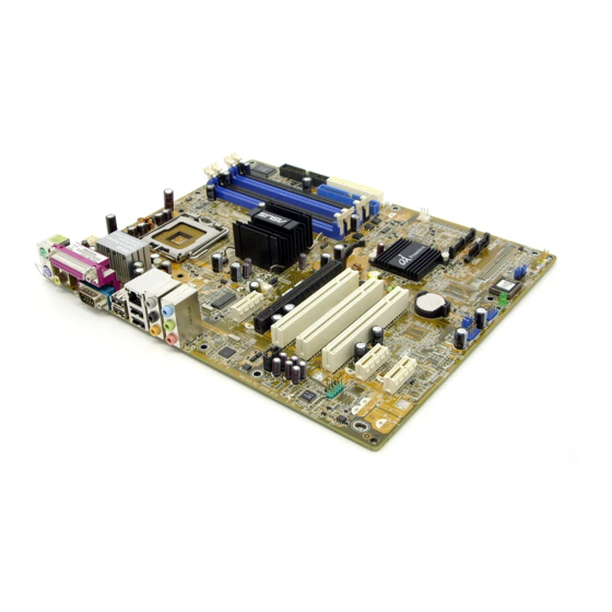
Page 20: Motherboard Layout
1.5.3 1.5.3 1.5.3 1.5.3 1.5.3 Motherboard layout Motherboard layout Motherboard layout Motherboard layout Motherboard layout 24.5cm (9.6in) KBPWR PS/2KBMS T: Mouse B: Keyboard ATX12V SPDIF_O LGA775 COM1 F_USB12 USBPW12 USBPW34 LAN_USB12 Intel Top: Grantsdale-P Back surround L/R Center: Side surround L/R Below: Bass Top:Line In... -
Page 21: Central Processing Unit (Cpu)
Contact your retailer immediately if the PnP cap is missing, or if you see any damage to the PnP cap/socket pins/motherboard components. ASUS will shoulder the cost of repair only if the damage is shipment/ transit-related. •... - Page 22 Press the load lever with your thumb (A) and move it to the left (B) until it is released from the retention tab. P n P C a p P n P C a p P n P C a p P n P C a p P n P C a p R e t e n t i o n t a b...
- Page 23 Close the load plate (A), then push the load lever (B) until it snaps into the retention tab. The CPU fits in only one correct orientation. DO NOT force the CPU into the socket to prevent bending the connectors on the socket and damaging the CPU! Notes on Intel Notes on Intel...
-
Page 24: Installling The Cpu Heatsink And Fan
1.6.2 1.6.2 1.6.2 Installling the CPU heatsink and fan Installling the CPU heatsink and fan Installling the CPU heatsink and fan 1.6.2 1.6.2 Installling the CPU heatsink and fan Installling the CPU heatsink and fan The Intel ® Pentium ® 4 LGA775 processor requires a specially designed heatsink and fan assembly to ensure optimum thermal condition and performance. - Page 25 Push each of the pins downward to secure the heatsink and fan assembly in place. When the fan and heatsink assembly is in place, connect the CPU fan cable to the connector on the motherboard labeled CPU_FAN. CPU_FAN CPU FAN PWR CPU FAN IN CPU FAN PWM P5GD1...
-
Page 26: System Memory
System memory 1.7.1 1.7.1 1.7.1 1.7.1 1.7.1 Overview Overview Overview Overview Overview The motherboard comes with four 184-pin Double Data Rate (DDR) Dual Inline Memory Modules (DIMM) sockets. The following figure illustrates the location of the sockets: P5GD1 PRO P5GD1 PRO 184-pin DDR DIMM sockets 1.7.2 1.7.2 1.7.2... - Page 27 Table 1 Table 1 Recommended memory configurations Recommended memory configurations Table 1 Table 1 Table 1 Recommended memory configurations Recommended memory configurations Recommended memory configurations S o c k e t s S o c k e t s S o c k e t s S o c k e t s S o c k e t s M o d e...
- Page 28 DDR400 Qualified Vendors List DDR400 Qualified Vendors List DDR400 Qualified Vendors List DDR400 Qualified Vendors List DDR400 Qualified Vendors List D I M M s u p p o r t D I M M s u p p o r t D I M M s u p p o r t D I M M s u p p o r t D I M M s u p p o r t...
-
Page 29: Installing A Dimm
1.7.3 1.7.3 1.7.3 Installing a DIMM Installing a DIMM Installing a DIMM 1.7.3 1.7.3 Installing a DIMM Installing a DIMM Make sure to unplug the power supply before adding or removing DIMMs or other system components. Failure to do so may cause severe damage to both the motherboard and the components. -
Page 30: Expansion Slots
Expansion slots In the future, you may need to install expansion cards. The following sub-sections describe the slots and the expansion cards that they support. Make sure to unplug the power cord before adding or removing expansion cards. Failure to do so may cause you physical injury and damage motherboard components. -
Page 31: Interrupt Assignments
1.8.3 1.8.3 1.8.3 1.8.3 1.8.3 Interrupt assignments Interrupt assignments Interrupt assignments Interrupt assignments Interrupt assignments Standard interrupt assignments Standard interrupt assignments Standard interrupt assignments Standard interrupt assignments Standard interrupt assignments I R Q I R Q I R Q I R Q I R Q P r i o r i t y P r i o r i t y... -
Page 32: Pci Slots
1.8.4 1.8.4 1.8.4 PCI slots PCI slots PCI slots 1.8.4 1.8.4 PCI slots PCI slots The PCI slots support cards such as a LAN card, SCSI card, USB card, and other cards that comply with PCI specifications. The figure shows a LAN card installed on a PCI slot. -
Page 33: Jumpers
Jumpers 1 . 1 . C l e a r R T C R A M ( C L R T C ) C l e a r R T C R A M ( C L R T C ) C l e a r R T C R A M ( C L R T C ) C l e a r R T C R A M ( C L R T C ) C l e a r R T C R A M ( C L R T C ) - Page 34 2 . 2 . U S B d e v i c e w a k e - u p ( 3 - p i n U S B P W 1 2 , U S B P W 3 4 , U S B d e v i c e w a k e - u p ( 3 - p i n U S B P W 1 2 , U S B P W 3 4 , U S B d e v i c e w a k e - u p ( 3 - p i n U S B P W 1 2 , U S B P W 3 4 , U S B d e v i c e w a k e - u p ( 3 - p i n U S B P W 1 2 , U S B P W 3 4 ,...
- Page 35 3 . 3 . K e y b o a r d p o w e r ( 3 - p i n K B P W R ) K e y b o a r d p o w e r ( 3 - p i n K B P W R ) K e y b o a r d p o w e r ( 3 - p i n K B P W R ) K e y b o a r d p o w e r ( 3 - p i n K B P W R ) K e y b o a r d p o w e r ( 3 - p i n K B P W R )
-
Page 36: 1.10 Connectors
1.10 Connectors 1.10.1 1.10.1 Rear panel connectors Rear panel connectors 1.10.1 1.10.1 1.10.1 Rear panel connectors Rear panel connectors Rear panel connectors 1 . 1 . P S / 2 m o u s e p o r t ( g r e e n ) . P S / 2 m o u s e p o r t ( g r e e n ) . - Page 37 Refer to the audio configuration table for the function of the audio ports in 2, 4, 6, or 8-channel configuration. Audio 2, 4, 6, or 8-channel configuration Audio 2, 4, 6, or 8-channel configuration Audio 2, 4, 6, or 8-channel configuration Audio 2, 4, 6, or 8-channel configuration Audio 2, 4, 6, or 8-channel configuration P o r t...
-
Page 38: Internal Connectors
1.10.2 1.10.2 Internal connectors 1.10.2 Internal connectors Internal connectors Internal connectors 1.10.2 1.10.2 Internal connectors 1 . 1 . F l o p p y d i s k d r i v e c o n n e c t o r ( 3 4 - 1 p i n F L O P P Y ) F l o p p y d i s k d r i v e c o n n e c t o r ( 3 4 - 1 p i n F L O P P Y ) F l o p p y d i s k d r i v e c o n n e c t o r ( 3 4 - 1 p i n F L O P P Y ) F l o p p y d i s k d r i v e c o n n e c t o r ( 3 4 - 1 p i n F L O P P Y ) -
Page 39: Hard Disk Drives
3 . 3 . S e r i a l A T A c o n n e c t o r s S e r i a l A T A c o n n e c t o r s S e r i a l A T A c o n n e c t o r s S e r i a l A T A c o n n e c t o r s S e r i a l A T A c o n n e c t o r s... - Page 40 5 . 5 . C P U , C h a s s i s , a n d P o w e r f a n c o n n e c t o r s C P U , C h a s s i s , a n d P o w e r f a n c o n n e c t o r s C P U , C h a s s i s , a n d P o w e r f a n c o n n e c t o r s C P U , C h a s s i s , a n d P o w e r f a n c o n n e c t o r s C P U , C h a s s i s , a n d P o w e r f a n c o n n e c t o r s...
-
Page 41: Atx Power Connectors
7 . 7 . A T X p o w e r c o n n e c t o r s ( 2 4 - p i n E A T X P W R , A T X p o w e r c o n n e c t o r s ( 2 4 - p i n E A T X P W R , A T X p o w e r c o n n e c t o r s ( 2 4 - p i n E A T X P W R , 4 - p i n A T X 1 2 V ) 4 - p i n A T X 1 2 V ) - Page 42 8 . 8 . O p t i c a l d r i v e a u d i o c o n n e c t o r ( 4 - p i n C D ) O p t i c a l d r i v e a u d i o c o n n e c t o r ( 4 - p i n C D ) O p t i c a l d r i v e a u d i o c o n n e c t o r ( 4 - p i n C D ) O p t i c a l d r i v e a u d i o c o n n e c t o r ( 4 - p i n C D ) O p t i c a l d r i v e a u d i o c o n n e c t o r ( 4 - p i n C D )
- Page 43 1 0 . 1 0 . F r o n t p a n e l a u d i o c o n n e c t o r ( 1 0 - 1 p i n A A F P ) 1 0 .
-
Page 44: System Panel Connector
1 2 . 1 2 . 1 2 . 1 2 . 1 2 . S y s t e m p a n e l c o n n e c t o r ( 2 0 - p i n P A N E L ) S y s t e m p a n e l c o n n e c t o r ( 2 0 - p i n P A N E L ) S y s t e m p a n e l c o n n e c t o r ( 2 0 - p i n P A N E L ) S y s t e m p a n e l c o n n e c t o r ( 2 0 - p i n P A N E L ) -
Page 45: Chapter 2: Bios Setup
This chapter tells how to change the system settings through the BIOS Setup menus. Detailed descriptions of the BIOS parameters are also provided. BIOS setup A S U S P 5 G D 1 P R O A S U S P 5 G D 1 P R O A S U S P 5 G D 1 P R O 2 - 1 2 - 1... -
Page 46: Managing And Updating Your Bios
Refer to the corresponding sections for details on these utilities. Save a copy of the original motherboard BIOS file to a bootable floppy disk in case you need to restore the BIOS in the future. Copy the original motherboard BIOS using the ASUS Update or AFUDOS utilities. 2.1.1 2.1.1 2.1.1... -
Page 47: Asus Ez Flash Utility
ASUS EZ Flash utility ASUS EZ Flash utility The ASUS EZ Flash feature allows you to update the BIOS without having to go through the long process of booting from a floppy disk and using a DOS-based utility. The EZ Flash utility is built-in the BIOS chip so it is accessible by pressing <Alt>... -
Page 48: Afudos Utility
2.1.3 2.1.3 2.1.3 AFUDOS utility AFUDOS utility AFUDOS utility 2.1.3 2.1.3 AFUDOS utility AFUDOS utility The AFUDOS utility allows you to update the BIOS file in DOS environment using a bootable floppy disk with the updated BIOS file. This utility also allows you to copy the current BIOS file that you can use as backup when the BIOS fails or gets corrupted during the updating process. - Page 49 Updating the BIOS file To update the BIOS file using the AFUDOS utility: Visit the ASUS website (www.asus.com) and download the latest BIOS file for the motherboard. Save the BIOS file to a bootable floppy disk. Write the BIOS filename on a piece of paper. You need to type the exact BIOS filename at the DOS prompt.
-
Page 50: Asus Crashfree Bios 2 Utility
ASUS CrashFree BIOS 2 utility ASUS CrashFree BIOS 2 utility The ASUS CrashFree BIOS 2 is an auto recovery tool that allows you to restore the BIOS file when it fails or gets corrupted during the updating process. You can update a corrupted BIOS file using the motherboard support CD or the floppy disk that contains the updated BIOS file. - Page 51 Restart the system after the utility completes the updating process. The recovered BIOS may not be the latest BIOS version for this motherboard. Visit the ASUS website (www.asus.com) to download the latest BIOS file. A S U S P 5 G D 1 P R O...
-
Page 52: Asus Update Utility
ASUS Update utility 2.1.5 2.1.5 ASUS Update utility ASUS Update utility The ASUS Update is a utility that allows you to manage, save, and update the motherboard BIOS in Windows ® environment. The ASUS Update utility allows you to: • Save the current BIOS file •... - Page 53 Updating the BIOS through the Internet Updating the BIOS through the Internet Updating the BIOS through the Internet To update the BIOS through the Internet: Launch the ASUS Update utility from the Windows ® desktop by clicking S t a r t...
- Page 54 A S U S U p d a t e A S U S U p d a t e. The ASUS Update main window appears. U p d a t e B I O S f r o m a...
-
Page 55: Bios Setup Program
• Visit the ASUS website (www.asus.com) to download the latest BIOS file for this motherboard and . A S U S P 5 G D 1 P R O... -
Page 56: Bios Menu Screen
Language [English] Use [+] or [-] to Primary IDE Master :[ST320413A] configure system time. Primary IDE Slave :[ASUS CD-S340] Secondary IDE Master :[Not Detected] Secondary IDE Slave :[Not Detected] Third IDE Master :[Not Detected] Fourth IDE Master... -
Page 57: Menu Items
For example, selecting M a i n M a i n M a i n M a i n shows the M a i n Primary IDE Slave :[ASUS CD-S340] Secondary IDE Master :[Not Detected] Secondary IDE Slave :[Not Detected] Third IDE Master :[Not Detected] Main menu items. -
Page 58: Main Menu
Main menu When you enter the BIOS Setup program, the Main menu screen appears, giving you an overview of the basic system information. Refer to section “2.2.1 BIOS menu screen” for information on the menu screen items and how to navigate through them. System Time [11:51:19] System Date... -
Page 59: Primary, Third And Fourth Ide Master/Slave
2.3.5 2.3.5 2.3.5 Primary, Third and Fourth IDE Master/Slave Primary, Third and Fourth IDE Master/Slave Primary, Third and Fourth IDE Master/Slave 2.3.5 2.3.5 Primary, Third and Fourth IDE Master/Slave Primary, Third and Fourth IDE Master/Slave While entering Setup, the BIOS automatically detects the presence of IDE devices. -
Page 60: Ide Configuration
PIO Mode [Auto] PIO Mode [Auto] PIO Mode [Auto] PIO Mode [Auto] PIO Mode [Auto] Selects the PIO mode. Configuration options: [Auto] [0] [1] [2] [3] [4] DMA Mode [Auto] DMA Mode [Auto] DMA Mode [Auto] DMA Mode [Auto] DMA Mode [Auto] Selects the DMA mode. - Page 61 Onboard IDE Operate Mode [Enhanced Mode] Onboard IDE Operate Mode [Enhanced Mode] Onboard IDE Operate Mode [Enhanced Mode] Onboard IDE Operate Mode [Enhanced Mode] Onboard IDE Operate Mode [Enhanced Mode] Allows selection of the IDE operation mode depending on the operating system (OS) that you installed.
-
Page 62: System Information
IDE Detect Time Out [35] IDE Detect Time Out [35] IDE Detect Time Out [35] IDE Detect Time Out [35] IDE Detect Time Out [35] Selects the time out value for detecting ATA/ATAPI devices. Configuration options: [0] [5] [10] [15] [20] [25] [30] [35] 2.3.7 2.3.7 2.3.7... -
Page 63: Advanced Menu
A I N O S A I N O S A I N O S A I N O S - the ASUS AI Non-delay Overclocking System feature intelligently determines the system load and automatically boost the performance for the most demanding tasks. - Page 64 Performance Mode [Auto] Performance Mode [Auto] Performance Mode [Auto] Performance Mode [Auto] Performance Mode [Auto] Allows enhanced system performance. Setting to [Turbo] may cause the system to become unstable. If this happens, revert to the default setting [Auto]. Configuration options: [Auto] [Standard] [Turbo] The following item appears only when the AI Overclocking item is set to [Overclock Profile].
- Page 65 The following item appears only when the AI Overclocking item is set to [AI N.O.S.] or [Manual]. Memory Voltage [Auto] Memory Voltage [Auto] Memory Voltage [Auto] Memory Voltage [Auto] Memory Voltage [Auto] Allows selection of the DDR SDRAM operating voltage. Set to Auto for safe mode.
-
Page 66: Lan Cable Status
DRAM Frequency [Auto] DRAM Frequency [Auto] DRAM Frequency [Auto] DRAM Frequency [Auto] DRAM Frequency [Auto] Allows you to set the DDR operating frequency. Configuration options: [Auto] [400 MHz] [533 MHz] [600 MHz] Selecting a DRAM frequency that is not supported by your DIMM module may cause the system to become unstable! If this happens, revert to the default setting. -
Page 67: Usb Configuration
2.4.3 2.4.3 2.4.3 USB Configuration USB Configuration USB Configuration 2.4.3 2.4.3 USB Configuration USB Configuration The items in this menu allows you to change the USB-related features. Select an item then press <Enter> to display the configuration options. USB Configuration Module Version - 2.23.2-9.4 USB Devices Enabled: None USB Function... -
Page 68: Cpu Configuration
2.4.4 2.4.4 2.4.4 2.4.4 2.4.4 CPU Configuration CPU Configuration CPU Configuration CPU Configuration CPU Configuration The items in this menu show the CPU-related information that the BIOS automatically detects. Configure Advanced CPU settings Sets the ratio between CPU Core Clock and the Manufacturer: Intel FSB Frequency. -
Page 69: Chipset
CPU Internal Thermal Control [Auto] CPU Internal Thermal Control [Auto] CPU Internal Thermal Control [Auto] CPU Internal Thermal Control [Auto] CPU Internal Thermal Control [Auto] Disables or sets the CPU internal thermal control. Configuration options: [Disabled] [Auto] Hyper-Threading Technology [Enabled] Hyper-Threading Technology [Enabled] Hyper-Threading Technology [Enabled] Hyper-Threading Technology [Enabled]... - Page 70 DRAM RAS# to CAS# Delay [4 Clocks] Controls the latency between the DDR SDRAM active command and the read/write command. Configuration options: [2 Clocks] [3 Clocks] [4 Clocks] [5 Clocks] DRAM RAS# Activate to Precharge [15 Clocks] Sets the RAS Activate timing to Precharge timing. Configuration options: [1 Clock] [2 Clocks] ~ [15 Clocks] DRAM Write Recovery Time [4 Clocks] Sets the DRAM Write Recover Time.
-
Page 71: Onboard Devices Configuration
2.4.6 2.4.6 2.4.6 Onboard Devices Configuration Onboard Devices Configuration Onboard Devices Configuration 2.4.6 2.4.6 Onboard Devices Configuration Onboard Devices Configuration Configure Win627EHF Super IO Chipset Enable or Disable High Definition Audio HD Audio Controller [Enabled] Controller Onboard LAN [Enabled] LAN Option ROM [Disabled] Serial Port1 Address [3F8/IRQ4]... -
Page 72: Pci Pnp
Parallel Port IRQ [IRQ7] Configuration options: [IRQ5] [IRQ7] 2.4.7 2.4.7 2.4.7 PCI PnP PCI PnP PCI PnP 2.4.7 2.4.7 PCI PnP PCI PnP The PCI PnP menu items allow you to change the advanced settings for PCI/PnP devices. The menu includes setting IRQ and DMA channel resources for either PCI/PnP or legacy ISA devices, and setting the memory size block for legacy ISA devices. - Page 73 Palette Snooping [Disabled] Palette Snooping [Disabled] Palette Snooping [Disabled] Palette Snooping [Disabled] Palette Snooping [Disabled] When set to [Enabled], the pallete snooping feature informs the PCI devices that an ISA graphics device is installed in the system so that the latter can function correctly.
-
Page 74: Power Menu
Power menu The Power menu items allow you to change the settings for the Advanced Configuration and Power Interface (ACPI) and the Advanced Power Management (APM). Select an item then press <Enter> to display the configuration options. Configure CPU. Suspend Mode [Auto] Repost Video on S3 Resume [No]... -
Page 75: Apm Configuration
2.5.5 2.5.5 2.5.5 APM Configuration APM Configuration APM Configuration 2.5.5 2.5.5 APM Configuration APM Configuration APM Configuration Enabled or disable APM. Power Button Mode [On/Off] Restore on AC Power Loss [Power Off] Power On By RTC Alarm [Disabled] Power On By External Modems [Disabled] Power On By PCI/PCIEX Devices [Disabled]... - Page 76 Power On By PCI Devices [Disabled] Power On By PCI Devices [Disabled] Power On By PCI Devices [Disabled] Power On By PCI Devices [Disabled] Power On By PCI Devices [Disabled] When set to [Enabled], this parameter allows you to turn on the system through a PCI LAN or modem card.
-
Page 77: Hardware Monitor
CPU Q-Fan Control [Disabled] CPU Q-Fan Control [Disabled] CPU Q-Fan Control [Disabled] Allows you to enable or disable the ASUS Q-Fan feature that smartly adjusts the fan speeds for more efficient system operation. Configuration options: [Disabled] [Enabled] C P U F a n R a t i o... -
Page 78: Boot Menu
CPU Target Temperature [xxxºC] CPU Target Temperature [xxxºC] CPU Target Temperature [xxxºC] CPU Target Temperature [xxxºC] CPU Target Temperature [xxxºC] Allows you to set the CPU temperature threshold when the CPU fan speed is increased to lower the CPU temperature. This item appears only when the CPU Q-Fan Control item is Enabled. -
Page 79: Boot Device Priority
This allows you to enable or disable the full screen logo display feature. Configuration options: [Disabled] [Enabled] Set this item to [Enabled] to use the ASUS MyLogo™ feature. A S U S P 5 G D 1 P R O... - Page 80 Add On ROM Display Mode [Force BIOS] Add On ROM Display Mode [Force BIOS] Add On ROM Display Mode [Force BIOS] Add On ROM Display Mode [Force BIOS] Add On ROM Display Mode [Force BIOS] Sets the display mode for option ROM. Configuration options: [Force BIOS] [Keep Current] Bootup Num-Lock [On] Bootup Num-Lock [On]...
-
Page 81: Security
2.6.3 2.6.3 2.6.3 Security Security Security 2.6.3 2.6.3 Security Security The Security menu items allow you to change the system security settings. Select an item then press <Enter> to display the configuration options. Security Settings <Enter> to change password. Supervisor Password : Not Installed <Enter>... - Page 82 After you have set a supervisor password, the other items appear to allow you to change other security settings. Security Settings Supervisor Password : Not Installed User Password : Not Installed Change Supervisor Password User Access Level [Full Access] Change User Password Clear User Password Password Check [Setup]...
-
Page 83: Exit Menu
Password Check [Setup] Password Check [Setup] Password Check [Setup] Password Check [Setup] Password Check [Setup] When set to [Setup], BIOS checks for user password when accessing the Setup utility. When set to [Always], BIOS checks for user password both when accessing Setup and booting the system. Configuration options: [Setup] [Always] Boot Sector Virus Protection [Disabled] Boot Sector Virus Protection [Disabled]... - Page 84 If you attempt to exit the Setup program without saving your changes, the program prompts you with a message asking if you want to save your changes before exiting. Press <Enter> to save the changes while exiting. Exit & Discard Changes Exit &...
- Page 85 This chapter describes the contents of the support CD that comes with the motherboard package. Software support A S U S P 5 G D 1 P R O A S U S P 5 G D 1 P R O A S U S P 5 G D 1 P R O 3 - 1 3 - 1...
-
Page 86: Installing An Operating System
The support CD that came with the motherboard package contains the drivers, software applications, and utilities that you can install to avail all motherboard features. The contents of the support CD are subject to change at any time without notice. Visit the ASUS website(www.asus.com) for updates. 3.2.1 3.2.1 3.2.1... -
Page 87: Drivers Menu
3.2.2 3.2.2 3.2.2 3.2.2 3.2.2 Drivers menu Drivers menu Drivers menu Drivers menu Drivers menu The drivers menu shows the available device drivers if the system detects installed devices. Install the necessary drivers to activate the devices. QFE Update QFE Update QFE Update QFE Update QFE Update... -
Page 88: Utilities Menu
Internet Service Provider (ISP). See page 2-8 for details. ASUS Ai Booster ASUS Ai Booster ASUS Ai Booster ASUS Ai Booster ASUS Ai Booster The ASUS Ai Booster application allows you to overclock the CPU speed in a Windows ® environment. Microsoft DirectX Microsoft DirectX Microsoft DirectX... -
Page 89: Manuals Menu
Installs the Adobe ® Acrobat ® Reader V5.0. ASUS Screen Saver ASUS Screen Saver ASUS Screen Saver ASUS Screen Saver ASUS Screen Saver Installs the ASUS screen saver. 3.2.4 3.2.4 3.2.4 3.2.4 3.2.4 Manuals menu Manuals menu Manuals menu Manuals menu Manuals menu The Manuals menu contains a list of supplementary user manuals. -
Page 90: Asus Contact Information
C o n t a c t C o n t a c t C o n t a c t tab to display the ASUS contact information. You can C o n t a c t also find this information on the inside front cover of this user guide. -
Page 91: Raid Configurations
RAID configurations The motherboard comes with the Intel ® ICH6R Southbridge RAID controller that allow you to configure IDE and Serial ATA hard disk drives as RAID sets. The motherboard supports the following RAID configurations. R A I D 0 R A I D 0 (Data striping) optimizes two identical hard disk drives to read and R A I D 0 R A I D 0... -
Page 92: Installing Hard Disks
3.3.1 3.3.1 3.3.1 Installing hard disks Installing hard disks Installing hard disks 3.3.1 3.3.1 Installing hard disks Installing hard disks The motherboard supports Ultra DMA 133/100/66 and Serial ATA hard disk drives. For optimal performance, install identical drives of the same model and capacity when creating a disk array. -
Page 93: Intel Raid Configurations
3.3.2 3.3.2 3.3.2 Intel Intel Intel ® ® ® ® ® RAID configurations RAID configurations RAID configurations 3.3.2 3.3.2 Intel Intel RAID configurations RAID configurations This motherboard supports RAID 0, RAID 1, and Intel ® Matrix Storage configurations for Serial ATA hard disks drives through the Intel ®... - Page 94 At the bottom of the screen are the navigation keys. These keys allow you to move through and select menu options. ]-Change ]-Change [TAB]-Next [TAB]-Next [ESC] Previous Menu [ESC] Previous Menu [Enter]-Select [Enter]-Select Creating a RAID Volume Creating a RAID Volume Creating a RAID Volume Creating a RAID Volume Creating a RAID Volume...
- Page 95 T I P : T I P : T I P : T I P : T I P : For server systems, use of a lower array block size is recommended. For multimedia computer systems used mainly for audio and video editing, a higher array block size is recommended for optimum performance.
- Page 96 Press <Del> to delete the RAID volume. The following confirmation message appears. VOLUME DELETE VERIFICATION ALL DATA IN THE VOLUME WILL BE LOST!! Are you sure you want to delete volume "RAID_Volume0"? (Y/N) Press <Y> to confirm or <N> to return to the configuration Main Menu. Resetting RAID Disks Drives Resetting RAID Disks Drives Resetting RAID Disks Drives...