Epson R260 - Stylus Photo Color Inkjet Printer Service Manual
Color inkjet printer
Hide thumbs
Also See for R260 - Stylus Photo Color Inkjet Printer:
- Printer basics manual (82 pages) ,
- Supplementary manual (14 pages) ,
- Start here manual (8 pages)

Related Manuals for Epson R260 - Stylus Photo Color Inkjet Printer


Summary of Contents for Epson R260 - Stylus Photo Color Inkjet Printer
-
Page 1: Service Manual
SERVICE MANUAL Color Inkjet Printer EPSON Stylus Photo R260/R265/R270 R360/R380/R390 SEIJ06001... - Page 2 MAKE CERTAIN THAT THE SOURCE VOLTAGES IS THE SAME AS THE RATED VOLTAGE, LISTED ON THE SERIAL NUMBER/RATING PLATE. IF THE EPSON PRODUCT HAS A PRIMARY AC RATING DIFFERENT FROM AVAILABLE POWER SOURCE, DO NOT CONNECT IT TO THE POWER SOURCE.
-
Page 3: About This Manual
Provides Epson-approved methods for adjustment. CHAPTER 6.MAINTENANCE Provides preventive maintenance procedures and the lists of Epson- May indicate an operating or maintenance procedure, practice or approved lubricants and adhesives required for servicing the product. condition that is necessary to accomplish a task efficiently. It may also... - Page 4 2.2.3 Circuit Block Diagram (p.28): error correction Chapter 3 3.2.1 Error Indication Method (p.33): EPSON Status Monitor 3 error messages are changed. 3.3.1 Troubleshooting Problems with Error Messages (p.36) is modified. (CR Encoder) 3.4.4 Problems with Interfaces (p.55): Troubleshooting Memory Card are modified.
-
Page 5: Table Of Contents
EPSON Stylus Photo R260/R265/R270, R360/R380/R390 Revision B CONTENTS Chapter 1 Product description Chapter 3 Troubleshooting 1.1 Overview ......................9 3.1 Overview ......................32 1.1.1 Differences between R260/265/270 and R360/380/390......9 3.1.1 Troubleshooting on Motors and Sensors..........32 1.2 Basic Specifications.................... 10 3.2 Error/Warning Indications.................. - Page 6 EPSON Stylus Photo R260/R265/R270, R360/R380/R390 Revision B 4.2.8 Right Front Housing / Left Front Housing ..........72 5.3 Banding Reduction System (BRS) Adjustment/ Paper Feed Amount 4.2.9 Front Housing ..................73 Profile (PFP) Correction................... 124 5.3.1 Overview ....................124 4.3 Removing Control Boards.................. 76 5.3.2 Adjustment Procedure ................
- Page 7 C H A P T E R PRODUCT DESCRIPTION...
-
Page 8: Overview
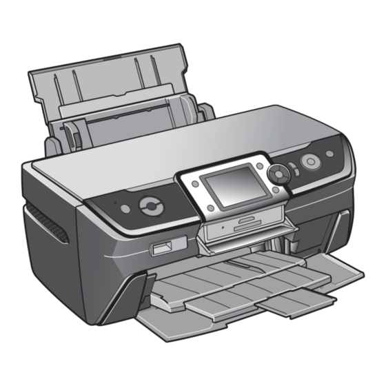
EPSON Stylus Photo R260/R265/R270, R360/R380/R390 Revision B 1.1 Overview 1.1.1 Differences between R260/265/270 and R360/380/390 Appearance Stylus Photo R260/R265/R270 and R360/R380/R390 are A4 home-use photo printers. R360/R380/R390 Besides printing on papers, printing directly on CDs/DVDs are available. The main features are;... -
Page 9: Basic Specifications
EPSON Stylus Photo R260/R265/R270, R360/R380/R390 Revision B 1.2 Basic Specifications Paper Feeding Table 1-3. Paper Feeding Specifications 1.2.1 Printing Item Description Paper feed method Friction feed with ASF (Auto Sheet Feeder) Basic Specifications Feed path Feeds from the top and ejects from the front Table 1-2. -
Page 10: Interfaces
EPSON Stylus Photo R260/R265/R270, R360/R380/R390 Revision B 1.2.2 Interfaces USB Host Port Table 1-6. USB Host Port Specifications The printers are equipped with the following interfaces. Item Description USB I/F Universal Serial Bus Specifications Revision 2.0 USB DEVICE (for connecting a PC) Standard Universal Serial Bus Mass Storage Class Bulk-Only Transport Revision 1.0”... - Page 11 EPSON Stylus Photo R260/R265/R270, R360/R380/R390 Revision B 1.2.2.3 Memory Card Slot (R360/R380/R390 only) Table 1-8. Compatible Card Types by the Card Slot Priority Slot Compatible Card Type Standard Remarks Compact Flash CF+ and CompactFlash Specification Revision 2.0 compliant Memory card only...
-
Page 12: Standalone Printing (R360/R380/R390 Only)
EPSON Stylus Photo R260/R265/R270, R360/R380/R390 Revision B 1.3 Standalone Printing PRINT Image Framer (P.I.F.) file (*.USD) (R360/R380/R390 only) A file that contains layout information that conforms to PRINT Image Framer Rev2.1. Only files in the “¥EPUDL¥” directory are valid. The Stylus Photo R360/R380/R390 offers Direct-Print function that allows the user to print directly from a memory card without using a PC. -
Page 13: Direct Print Of Movie Frames
EPSON Stylus Photo R260/R265/R270, R360/R380/R390 Revision B not guaranteed which files are selected when the number of files is 1000 or more. Image files associated with P.I.F.3 script When photo data files to which a camera has assigned numbers over 999 are specified When an image file associated with P.I.F.3 script file include a rotation tag, the image... -
Page 14: Backup Function (R360/R380/R390 Only)
EPSON Stylus Photo R260/R265/R270, R360/R380/R390 Revision B 1.4 Backup Function Available media type (R360/R380/R390 only) Table 1-10. Available Media Type Stylus Photo R360/R380/R390 allows the user to easily make a backup of his/her External Device Media Type Remarks memory card without using a computer. Furthermore, photos in a backup copy can be MO drive •... - Page 15 EPSON Stylus Photo R260/R265/R270, R360/R380/R390 Revision B Writing Format for CD-R Media Backup Restrictions Writing to CD-R media is made in multisession type (Model 1) and ISO-9660 (Joliet)- Browsing an external device from a PC cannot be made. compliant format.
- Page 16 EPSON Stylus Photo R260/R265/R270, R360/R380/R390 Revision B Backup-related errors Table 1-11. Backup-related Errors Error Description Message Remedy Backup error No external device is detected when a backup is attempted. External device is not connected or media is not inserted. Connect an external device.
-
Page 17: Cd/Dvd Print (R360/R380/R390 Only)
EPSON Stylus Photo R260/R265/R270, R360/R380/R390 Revision B 1.5 CD/DVD Print The table below lists the error codes controlled by the printer firmware. (R360/R380/R390 only) Table 1-12. Backup Error FW Control Code List Stylus Photo R360/R380/R390 provides the Print CD/DVD button that allows the user to... -
Page 18: Operation Panel
EPSON Stylus Photo R260/R265/R270, R360/R380/R390 Revision B 1.6 Operation Panel Table 1-13. R360/R380/R390 Button Functions Button Function Displays the menu to print directly on CDs/DVDs, or jackets for 1.6.1 Operation Panel Print CD/DVD them. Displays various setup menus such as maintenance menus (Change Appearance of the operation panels are shown below. -
Page 19: Indicator (Led)
EPSON Stylus Photo R260/R265/R270, R360/R380/R390 Revision B 1.6.2 Indicator (LED) Stylus Photo R260/R265/R270 Operation Panel Stylus Photo R360/R380/R390 Power LED Ink LED Paper LED These models are equipped with a 3.5inch color LCD (320x240) and one Power LED and two Mode LEDs on their control panel. -
Page 20: Specifications Common To The Models
EPSON Stylus Photo R260/R265/R270, R360/R380/R390 Revision B 1.7 Specifications Common to the Models 1.7.2 Environmental Condition Table 1-17. Environmental Condition 1.7.1 Electric Specifications Item Operating Storage* Table 1-15. Electric Specifications Temperature 10 to 35 °C -20 to 40 °C* Humidity (no condensation) -
Page 21: Dimensions
EPSON Stylus Photo R260/R265/R270, R360/R380/R390 Revision B 1.7.5 Dimensions Table 1-18. Dimensions Item R260/R265/R270 R360/R380/R390 Weight 6.2 kg 6.6 kg With covers closed 453 x 337 x 194 mm 453 x 343 x 194 mm Dimensions (W x D x H) - Page 22 C H A P T E R OPERATING PRINCIPLES...
-
Page 23: Overview
EPSON Stylus Photo R260/R265/R270, R360/R380/R390 Revision B 2.1 Overview Table 2-2. Main Control Boards Board Function This chapter describes the operating principles of the printer mechanism and electric Card Board Located on the Middle Housing. Incorporates memory card slots, circuit boards of Stylus Photo R260/R265/R270 and R360/R380/R390. -
Page 24: Motors & Sensors
EPSON Stylus Photo R260/R265/R270, R360/R380/R390 Revision B 2.1.2 Motors & Sensors Table 2-3. List of Motors & Sensors APG Sensor PF Motor Motor/Sensor Name Function PF Encoder Sensor Printhead F3-MACH head (6 colors x 90 nozzles) Type: DC motor ±... -
Page 25: Electrical Circuit Operating Principles
EPSON Stylus Photo R260/R265/R270, R360/R380/R390 Revision B 2.2 Electrical Circuit Operating Principles Features of C653Main Board (R260/R265/R270) The newly employed SOC achieves throughput enhancement. The The electric circuits of the Stylus Photo R260/R265/R270 and R360/R380/R390 incorporated USB host function offers USB host High Speed compatibility. -
Page 26: Components Of Control Boards
EPSON Stylus Photo R260/R265/R270, R360/R380/R390 Revision B 2.2.2 Components of Control Boards Table 2-5. Components of Control Boards Incorporated Components Board Name R360/R380/R390 R260/R265/R270 Logic circuit Logic circuit (ASIC incorporated in the CPU (ASIC incorporated in the CPU core, Flash ROM x 2, SDRAM x 1,... -
Page 27: Circuit Block Diagram
EPSON Stylus Photo R260/R265/R270, R360/R380/R390 Revision B 2.2.3 Circuit Block Diagram Data DDR-DRAM (IC7) Address Flash-ROM CN14 CR Motor (IC9) Motor Data PF Motor Driver CN15 (IC2) Address SDRAM (IC11) CPU-ASIC PF Encoder Sensor (IC4) (IC3) APG Sensor Serial Flash-ROM... - Page 28 EPSON Stylus Photo R260/R265/R270, R360/R380/R390 Revision B Flash-ROM (IC1) CN14 CR Motor Motor Driver PF Motor CN13 (IC8) SDRAM (IC2) CPU-ASIC PF Encoder Sensor (IC5) (IC3) APG Sensor Serial Flash-ROM PE Sensor (IC4) CDR Guide Sensor CDR Tray Sensor C653 Panel Board...
- Page 29 EPSON Stylus Photo R260/R265/R270, R360/R380/R390 Revision B 2.3 Banding Reduction System (BRS) / Paper Feed Amount Profile Correction (PFP) Overview In order to ensure high print quality and high print speed, this product incorporates the Banding Reduction System (BRS) and Paper Feed Profile (PFP) Correction system. The overview of them is described in the table below.
- Page 30 C H A P T E R TROUBLESHOOTING...
-
Page 31: Overview
EPSON Stylus Photo R260/R265/R270, R360/R380/R390 Revision B 3.1 Overview 3.1.1 Troubleshooting on Motors and Sensors The following tables show the normal electric values of each motor and sensor. When This chapter provides how to troubleshoot problems analyzing the cause based on the any abnormality is observed in motors and sensors, check their electric values and error messages displayed on the printer and the observed symptom. -
Page 32: Error/Warning Indications
Error messages are displayed on the LCD. • Figure 1-1. "Difference in Appearance"(p.9) Stylus Photo R260/R265/R270 Error messages can be checked with the LEDs and on the windows of “EPSON Status Monitor 3”. Figure 3-2. Error Indication on EPSON Status Monitor 3 •... - Page 33 EPSON Stylus Photo R260/R265/R270, R360/R380/R390 Revision B Table 3-4. List of Error Messages R360/R380/R390 R260/R265/R270 See the table for Error Name LED Indications STM3 Message Error Cause Troubleshooting Messages on the LCD Power Paper Check all connections and make sure all devices Communication are on.
- Page 34 EPSON Stylus Photo R260/R265/R270, R360/R380/R390 Revision B Table 3-4. List of Error Messages R360/R380/R390 R260/R265/R270 See the table for Error Name LED Indications STM3 Message Error Cause Troubleshooting Messages on the LCD Power Paper Paper out. Reload the paper and set the front tray to the paper position by pulling up the tray lever.
-
Page 35: Troubleshooting By Error Message
EPSON Stylus Photo R260/R265/R270, R360/R380/R390 Revision B 3.3 Troubleshooting by Error Message The following tables provide troubleshooting procedure for each error message indicated by the LCD or STM3 screen. When some parts need to be replaced or repaired, make sure to follow the procedure given in Chapter 4 and carry out required adjustments. - Page 36 EPSON Stylus Photo R260/R265/R270, R360/R380/R390 Revision B Table 3-6. Troubleshooting for Fatal Error Occurrence Symptom Failed Part Check Point Remedy Reference Timing 1. Is the CR motor cable not connected to the Main 1. Connect the cable correctly. Board? R360/R380/R390 4.3.2 "Removing the Main...
- Page 37 EPSON Stylus Photo R260/R265/R270, R360/R380/R390 Revision B Table 3-6. Troubleshooting for Fatal Error Occurrence Symptom Failed Part Check Point Remedy Reference Timing 1. Replace the ASF Unit. For the R360/R380/ 1. Is the Compression spring 2.36 of the Change R390, replace the Change Lever.
- Page 38 EPSON Stylus Photo R260/R265/R270, R360/R380/R390 Revision B Table 3-6. Troubleshooting for Fatal Error Occurrence Symptom Failed Part Check Point Remedy Reference Timing • The CR Unit hits 1. Is the PF Scale not moving freely, centered 1. Install the PF Scale or PF encoder correctly.
- Page 39 EPSON Stylus Photo R260/R265/R270, R360/R380/R390 Revision B Table 3-7. Troubleshooting for Ink Cartridge Detection Error/ Ink Cover Open Error/ Cartridge Empty Error Occurrence Symptom Failed Part Check Point Remedy Reference Timing 1. Is the memory chip on the cartridge chipped or 1.
- Page 40 EPSON Stylus Photo R260/R265/R270, R360/R380/R390 Revision B Table 3-8. Troubleshooting for Paper Jam Error Occurrence Symptom Failed Part Check Point Remedy Reference Timing 1. Is the ASF Unit installed incorrectly? 1. Install the ASF Unit correctly. 4.5.11 "ASF ASF Unit 2.
- Page 41 EPSON Stylus Photo R260/R265/R270, R360/R380/R390 Revision B Table 3-8. Troubleshooting for Paper Jam Error Occurrence Symptom Failed Part Check Point Remedy Reference Timing 3. Is the Torsion Spring 0.22 detached or attached 3. Install the PE Sensor Lever and the incorrectly? Torsion Spring 0.22 correctly.
- Page 42 EPSON Stylus Photo R260/R265/R270, R360/R380/R390 Revision B Table 3-9. Troubleshooting for No Paper Error Occurrence Symptom Failed Part Check Point Remedy Reference Timing 1. Is the Hopper not moving properly during the 1. Attach the Compression Spring 2.51 The LD Roller rotates normally to...
- Page 43 EPSON Stylus Photo R260/R265/R270, R360/R380/R390 Revision B Table 3-9. Troubleshooting for No Paper Error Occurrence Symptom Failed Part Check Point Remedy Reference Timing 3. Is the clutch damaged? 3. Replace the ASF Unit. LD Roller Clutch The PF Motor drive force is not ASF Assy 4.
- Page 44 EPSON Stylus Photo R260/R265/R270, R360/R380/R390 Revision B Table 3-10. Troubleshooting for CDR Tray Error Occurrence Symptom Failed Part Check Point Remedy Reference Timing 1. Has the part of the CDR Tray that contacts with 1. Replace the CDR Tray. the CDR Tray Sensor become cracked?
- Page 45 EPSON Stylus Photo R260/R265/R270, R360/R380/R390 Revision B Table 3-10. Troubleshooting for CDR Tray Error Occurrence Symptom Failed Part Check Point Remedy Reference Timing 1. Is there any paper dust or ink stain on the PW 1. Clean off any dirt on the PW Sensor.
- Page 46 EPSON Stylus Photo R260/R265/R270, R360/R380/R390 Revision B Table 3-11. Troubleshooting for CDR Guide Error Occurrence Symptom Failed Part Check Point Remedy Reference Timing 1. Is the CDR Guide Detection Assy cable not 1. Connect the cable to the Main Board.
-
Page 47: Troubleshooting By Symptom
EPSON Stylus Photo R260/R265/R270, R360/R380/R390 Revision B 3.4 Troubleshooting by Symptom 3.4.1 Problems in Printing Operation This section provides how to troubleshoot the possible problems on the printer mechanism. No error message appears for most of the troubles described here. In the following tables, find the symptom you face and follow the troubleshooting procedure given in the table. - Page 48 EPSON Stylus Photo R260/R265/R270, R360/R380/R390 Revision B Table 3-12. Troubleshooting Paper Feeding Problems Symptom Possible Cause Check Point Remedy Is the Extension Spring 1.98 at backside of the Retard Roller Attach the Extension Spring correctly. detached? Retard Roller Multiple sheets A malfunction of the Retard are fed at a time.
- Page 49 EPSON Stylus Photo R260/R265/R270, R360/R380/R390 Revision B Printer initialization operation is aborted Table 3-15. Troubleshooting Initialization Stop Problems Symptom Possible Cause Check Point Remedy Improper installation of the Are the tabs of the EJ Frame disengaged? Reinstall the EJ Frame correctly.
- Page 50 EPSON Stylus Photo R260/R265/R270, R360/R380/R390 Revision B Print quality problems Table 3-16. Troubleshooting Print Quality Problems Symptom Possible Cause Check Point Remedy Run a cleaning cycle and make a test print. Repeat the operation Clean the Printhead surface with a cotton swab.
- Page 51 EPSON Stylus Photo R260/R265/R270, R360/R380/R390 Revision B Table 3-16. Troubleshooting Print Quality Problems Symptom Possible Cause Check Point Remedy Dirt on the CR shaft Is there any dirt on the CR shaft? Clean off any dirt on the CR shaft surface with a dry soft cloth.
-
Page 52: Power Problems
EPSON Stylus Photo R260/R265/R270, R360/R380/R390 Revision B 3.4.2 Power Problems The printer does not work at all after power-on. LEDs do not light up. Table 3-17. Troubleshooting Power Problems Possible Cause Check Point Remedy Power code failure Replace the power code with a new one. Does the printer work normally? The power code is defective. - Page 53 EPSON Stylus Photo R260/R265/R270, R360/R380/R390 Revision B Printing cannot be made properly (printed image is faint, blurry, smeared, or etc.) Table 3-19. Troubleshooting Printing Problems Symptom Possible Cause Check Point Remedy Replace the ink cartridge with a new one, and make a test print.
-
Page 54: Problems With Interfaces
EPSON Stylus Photo R260/R265/R270, R360/R380/R390 Revision B 3.4.4 Problems with Interfaces This section provides how to troubleshoot problems on the USB interface and memory card slot. USB interface error Table 3-21. Troubleshooting USB Connection Errors Possible Cause Check Point Remedy... - Page 55 C H A P T E R DISASSEMBLY/ASSEMBLY...
-
Page 56: Overview
EPSON Stylus Photo R260/R265/R270, R360/R380/R390 Revision B 4.1 Overview Disconnect the power cable before disassembling or assembling the printer. This section describes procedures for disassembling the main components of the Stylus If you need to work on the printer with power applied, strictly Photo R260/R265/R270 and R360/R380/R390 follow the instructions in this manual. -
Page 57: Tools
EPSON Stylus Photo R260/R265/R270, R360/R380/R390 Revision B 4.1.2 Tools Table 4-2. List of Screw Types Description Image Use only specified tools to avoid damaging the printer. Table 4-1. List of Tools C.B.P 2.6x8 Tool Supplier* Part No. Phillips Screw Driver (No.1) -
Page 58: Work Completion Checklist
EPSON Stylus Photo R260/R265/R270, R360/R380/R390 Revision B 4.1.4 Work Completion Checklist Table 4-4. Work Completion Checklist Classification Item Check Point Status Whenever the printer is serviced, use the checklist shown below to confirm all work is completed properly and the printer is ready to be returned to the user. - Page 59 EPSON Stylus Photo R260/R265/R270, R360/R380/R390 Revision B Securing the Housing Middle (tape: 80mm x 2 pcs., fold one end by 5mm) PROTECTION FOR TRANSPORTATION Attach the two pieces of strong tape to the rear of the MIddle Housing as shown below.
-
Page 60: Required Preparation Before Disassembly
EPSON Stylus Photo R260/R265/R270, R360/R380/R390 Revision B 4.1.5 Required Preparation before Disassembly Protecting the exterior parts from scratches and scuff marks Have a commercially available 250cm-width x 100cm-length vinyl sheet to cover the Make sure to carry out the following operations before disassembling the printer. -
Page 61: How To Unlock The Carriage
EPSON Stylus Photo R260/R265/R270, R360/R380/R390 Revision B 4.1.7 How to Unlock the Carriage 4.1.8 Sharp Metal Edges (Danger!) Unlocking the carriage is required for disassembly of some parts or components. Carry out any of the following operations to unlock the carriage and move the During disassembly/reassembly work on the Stylus R260/R265/ carriage to other than its home position. -
Page 62: Differences In Disassembly Procedure By Model
EPSON Stylus Photo R260/R265/R270, R360/R380/R390 Revision B 4.1.9 Differences in Disassembly Procedure by Model The table below lists the differences in disassembly procedure between the Stylus Photo R260/R265/R270 and R360/R380/R390. For more details on each procedure, refer to the page given in the Reference column. -
Page 63: Disassembly/Assembly Procedures
EPSON Stylus Photo R260/R265/R270, R360/R380/R390 Revision B 4.1.10 Disassembly/Assembly Procedures The flowchart below lists the step-by-step disassembly procedures. When disassembling each unit, refer to the page number shown in the figure. START Right Housing / Left Housing / Paper Support (p.65) Printer Cover (p.65) -
Page 64: Removing Exterior Parts/Components
EPSON Stylus Photo R260/R265/R270, R360/R380/R390 Revision B 4.2 Removing Exterior Parts/Components 4.2.2 Printer Cover Parts/Components need to be removed in advance: Nothing 4.2.1 Paper Support Removal procedure Parts/Components need to be removed in advance: Nothing Open the Printer Cover. Removal procedure Pull out the left shaft and right shaft of the Printer Cover in that order, and remove the Printer Cover. -
Page 65: Front Cover
EPSON Stylus Photo R260/R265/R270, R360/R380/R390 Revision B 4.2.3 Front Cover 4.2.4 Right Housing / Left Housing / USB Housing Parts/Components need to be removed in advance: Nothing Parts/Components need to be removed in advance: Nothing Removal procedure Removal procedure Open the Front Cover. - Page 66 EPSON Stylus Photo R260/R265/R270, R360/R380/R390 Revision B Removing the USB Housing Push part to disengage the hook and slide the USB Housing upward to remove it. [Left side] Removal Direction Hook : Tab Figure 4-18. Disengaging the Hook and Tabs...
-
Page 67: Upper Housing
EPSON Stylus Photo R260/R265/R270, R360/R380/R390 Revision B 4.2.5 Upper Housing Be careful not to let the cables get caught under the Upper Housing at the position indicated with in Fig.4-22. Parts/Components need to be removed in advance Tighten the screws in the order given in Fig.4-21. -
Page 68: Panel Unit
EPSON Stylus Photo R260/R265/R270, R360/R380/R390 Revision B 4.2.6 Panel Unit Slide the Panel while pulling it upwards and disengage the two hooks. If the hooks do not disengage, insert a flathead screw driver into the hole of the Front Parts/Components need to be removed in advance... -
Page 69: Emi Frame / Waste Ink Tray
EPSON Stylus Photo R260/R265/R270, R360/R380/R390 Revision B 4.2.7 EMI Frame / Waste Ink Tray Follow the procedure below to install the EMI Frame. Insert (1) portion between the Shield Plate and the Main Parts/Components need to be removed in advance Frame. - Page 70 EPSON Stylus Photo R260/R265/R270, R360/R380/R390 Revision B Waste Ink Tray Removal Remove the two screws and remove the Waste Ink Tray. Screw : C.B.P. M3x10 (tightening torque: 5-7 kgf.cm) • When removing the Waste Ink Tray, take extra care not to spill (The numbers shown in the figure indicate the order of tightening the screws.)
-
Page 71: Right Front Housing / Left Front Housing
EPSON Stylus Photo R260/R265/R270, R360/R380/R390 Revision B 4.2.8 Right Front Housing / Left Front Housing Wipe off any ink on the joint portion of the Waste Ink Tube Parts/Components need to be removed in advance before reconnecting the tube. Ink on the joint portion makes the tube likely to get disconnected. -
Page 72: Front Housing
EPSON Stylus Photo R260/R265/R270, R360/R380/R390 Revision B 4.2.9 Front Housing Left Front Parts/Components need to be removed in advance Upper Tab Housing Paper Support / Printer Cover / Front Cover / Right Housing / Left Housing / Upper Housing / Panel Unit / EMI Frame / Waste Ink Tray / Right Front Housing / Left Front... - Page 73 EPSON Stylus Photo R260/R265/R270, R360/R380/R390 Revision B With a flathead screwdriver or similar tool, disengage the two tabs on the When removing the Front Housing, make sure to remove it in the inner left and right sides. specified direction without tilting it, otherwise the tip of the bottom...
- Page 74 EPSON Stylus Photo R260/R265/R270, R360/R380/R390 Revision B While pressing the Front Housing with your thumb holding the Install the Front Housing following the steps below Middle Housing with your other fingers as shown below, secure Install the Slot Cover. (R360/R380/R390 only) the screw (3) on the bottom left.
-
Page 75: Removing Control Boards
EPSON Stylus Photo R260/R265/R270, R360/R380/R390 Revision B 4.3 Removing Control Boards Remove the USB Shield Plate and the USB Board. USB Shield Plate 4.3.1 Removing the USB Board (R260/R265/R270 only) Parts/Components need to be removed in advance All exterior parts/components USB Board removal R260/R265/R270 are equipped with a USB Board. - Page 76 EPSON Stylus Photo R260/R265/R270, R360/R380/R390 Revision B From the rear side, push the positioning pin out with a screw driver or similar When putting the Head FFC through the Ferrite Core, first tool, and slide the FFC Holder upward to remove it from the Middle Housing.
-
Page 77: Removing The Main Board Unit
EPSON Stylus Photo R260/R265/R270, R360/R380/R390 Revision B 4.3.2 Removing the Main Board Unit For R260/R265/R270, when removing the connector cables, also remove the GND Cable of the USB Connector Cable (CN2). This Parts/Components need to be removed in advance GND Cable is screwed together with the Shield Plate in part... - Page 78 EPSON Stylus Photo R260/R265/R270, R360/R380/R390 Revision B Remove the four screws. (For R260/R265/R270, three screws only) Remove the Main Board, taking extra care not to get the FFC caught on the opening of the CB Support Shield Plate. (R360/R380/R390 only) Screw (3 pcs.): C.B.P.
-
Page 79: Disassembling The Main Board Unit
EPSON Stylus Photo R260/R265/R270, R360/R380/R390 Revision B 4.3.3 Disassembling the Main Board Unit Install the Main Board Unit following the steps below. Install the MB Frame to the the Lower Housing, and make Main Board Unit disassembly sure that the Ground Plate MB contacts with the Main Frame. - Page 80 EPSON Stylus Photo R260/R265/R270, R360/R380/R390 Revision B Remove the Upper Shield Plate MB from the Main Board following the steps Remove the two screws and remove the Lower Shield Plate MB from the Main below. Board. • Screw : C.P. M3x10 (tightening torque: 5-7 kgf.cm)
-
Page 81: Removing The Card Board (R360/R380/R390 Only)
EPSON Stylus Photo R260/R265/R270, R360/R380/R390 Revision B 4.3.4 Removing the Card Board (R360/R380/R390 only) Card Board disassembly Disconnect the FFC from CN1 connector on the Card Board. Parts/Components need to be removed in advance Remove the screw and remove the Ground Plate CB. -
Page 82: Disassembling The Panel Unit
EPSON Stylus Photo R260/R265/R270, R360/R380/R390 Revision B 4.3.5 Disassembling the Panel Unit Removing the Panel Board (for R360/R380/R390) Peel off the acetate tape. Panel Board removal Disengage the Ferrite Core from the hook. Be careful not to scratch or damage the exterior surface (coated or Ferrite core decorative laminated parts) during disassembly and reassembly. - Page 83 EPSON Stylus Photo R260/R265/R270, R360/R380/R390 Revision B Remove the screw and remove the Panel Board. Peel off the double-sided tape and remove the two FFCs from the Shield Plate PNL. Screw : C.B.P. M3x10 (tightening torque: 5-7 kgf.cm) • •...
- Page 84 EPSON Stylus Photo R260/R265/R270, R360/R380/R390 Revision B Remove the SW Button (1)(2)(3) and the LED Light Guide Plate. When attaching the SW Buttons, insert their guide pin into the corresponding positioning hole firmly. After installing the Shield Plate PNL, check the buttons for clicking operability by pressing each of them.
-
Page 85: Middle Housing
EPSON Stylus Photo R260/R265/R270, R360/R380/R390 Revision B 4.3.6 Middle Housing Remove the Middle Housing taking extra care not to get the FFC caught on the opening part. Parts/Components need to be removed in advance All exterior parts/components / Card Board (USB Board) / Main Board Unit... -
Page 86: Removing The Printer Mechanism
EPSON Stylus Photo R260/R265/R270, R360/R380/R390 Revision B 4.4 Removing the Printer Mechanism Do not touch the PF Scale with bare hands or damage it. If the Printer Mechanism is tilted leftward about 15°, the PF Parts/Components need to be removed in advance Scale hits against the desk surface and can break. - Page 87 EPSON Stylus Photo R260/R265/R270, R360/R380/R390 Revision B Remove the six screws that secure the Printer Mechanism. Before installing the Printer Mechanism, make sure that the cables Screw : C.B.P. M3x8 (tightening torque: 7-9 kgf.cm) • are correctly routed referring to the figure below and the following (The numbers shown in the figure indicate the order of tightening the screws.)
-
Page 88: Disassembly Of The Printer Mechanism
EPSON Stylus Photo R260/R265/R270, R360/R380/R390 Revision B 4.5 Disassembly of the Printer Mechanism Unlock the carriage and move the CR Unit to the center. Remove the Torsion Spring from the hook ( ) on the left side of the Main Frame. -
Page 89: Apg Unit
EPSON Stylus Photo R260/R265/R270, R360/R380/R390 Revision B 4.5.2 APG Unit Lubrication is required. See the page given below for the lubrication information. Take extra care to avoid injury from sharp metal edges. Before "6.1.3 Lubrication (p.131)" starting, see the page given below to check the dangerous edges. -
Page 90: Printhead
EPSON Stylus Photo R260/R265/R270, R360/R380/R390 Revision B 4.5.3 Printhead Install the APG Unit to the Main Frame. Take extra care to avoid injury from sharp metal edges. Before starting, see the page given below to check the dangerous edges. •... - Page 91 EPSON Stylus Photo R260/R265/R270, R360/R380/R390 Revision B Disconnect the FFC from the connector ( ) on the Head Board. Move the CR Unit to the left (the opposite side to the home position). Taking care not to scratch the cables, insert a flathead screw driver through the hole on the left rear of the Main Frame, and disengage the hook (2) of the CSIC Assy.
- Page 92 EPSON Stylus Photo R260/R265/R270, R360/R380/R390 Revision B 11. Remove the two Head FFCs from the connector on the back, and remove the Take extra care not to spill ink and contaminate the surroundings. Printhead. Be extremely careful not to touch the nozzle surface, the ink supply needles and the Head Cover, otherwise the nozzles may get clogged.
-
Page 93: Waste Ink Pad
EPSON Stylus Photo R260/R265/R270, R360/R380/R390 Revision B 4.5.4 Waste Ink Pad 4.5.5 P/S Assy Parts/Components need to be removed in advance Parts/Components need to be removed in advance All exterior parts/ All control boards / Middle Housing / Printer Mechanism... -
Page 94: Stacker Assy
EPSON Stylus Photo R260/R265/R270, R360/R380/R390 Revision B 4.5.6 Stacker Assy Remove the screw that secures the P/S Assy, and remove the P/S Assy from the Lower Housing. Parts/Components need to be removed in advance • Screw : C.B.P M3x10 (tightening torque: 5-7 kgf.cm) - Page 95 EPSON Stylus Photo R260/R265/R270, R360/R380/R390 Revision B Follow the steps below to remove the CDR Guide Lever Spring. While disengaging the hook, remove the left gear from the CDR Shaft and remove the Left Stacker Guide. Also remove the Right Stacker Guide in the 1) Pull the end A toward you.
-
Page 96: Ink System
EPSON Stylus Photo R260/R265/R270, R360/R380/R390 Revision B 4.5.7 Ink System When installing the Stacker Assy, insert the tabs of the Left/ Right Stacker Guides into the hole of the Lower Housing, and Take extra care to avoid injury from sharp metal edges. Before secure the guides with the screws. - Page 97 EPSON Stylus Photo R260/R265/R270, R360/R380/R390 Revision B Move the CR Unit to the center. Pull out the Ink System towards the front to remove it avoiding contact of the Pump and the rib of the opening. Remove the screw (1) that secures the Cap section.
-
Page 98: Cr Motor
EPSON Stylus Photo R260/R265/R270, R360/R380/R390 Revision B 4.5.8 CR Motor Remove the Driven Pulley Assy and remove the Timing Belt from the Pinion Gear of the CR Motor. Take extra care to avoid injury from sharp metal edges. Before Driven Pulley Assy starting, see the page given below to check the dangerous edges. -
Page 99: Ej Frame Assy
EPSON Stylus Photo R260/R265/R270, R360/R380/R390 Revision B 4.5.9 EJ Frame Assy Lubrication is required. See the page given below for the lubrication information. Take extra care to avoid injury from sharp metal edges. Before "6.1.3 Lubrication (p.131)" starting, see the page given below to check the dangerous edges. - Page 100 EPSON Stylus Photo R260/R265/R270, R360/R380/R390 Revision B Disengage the connector cables of the PE Sensor and the APG Sensor from Remove the EJ Frame Assy. the two hooks (A). Remove the two screws and remove the Cable Holder Frame from the two hooks (B).
-
Page 101: Pf Encoder / Pf Scale / Pf Motor
EPSON Stylus Photo R260/R265/R270, R360/R380/R390 Revision B 4.5.10 PF Encoder / PF Scale / PF Motor When installing the Front Frame, screw it after securing the foot of the two EJ Frame Springs to the slits as shown in the figure. - Page 102 EPSON Stylus Photo R260/R265/R270, R360/R380/R390 Revision B Removing the PF Motor Install the PF motor so that its label faces toward you. Peel off the acetate tape (1), and remove the Ferrite Core from the cutout of Tighten the screws in the order given in Fig.4-137.
-
Page 103: Asf Unit
EPSON Stylus Photo R260/R265/R270, R360/R380/R390 Revision B 4.5.11 ASF Unit Remove the Torsion Spring 137.7 from the LD Roller Guide. Parts/Components need to be removed in advance Torsion Spring All exterior parts/ All control boards / Middle Housing / Printer Mechanism / Ink... -
Page 104: Cr Unit
EPSON Stylus Photo R260/R265/R270, R360/R380/R390 Revision B 4.5.12 CR Unit Remove the Combination Gear (10, 15.2), and remove the ASF Unit. Parts/Components need to be removed in advance All exterior parts/ All control boards / Middle Housing / Printer Mechanism / CR Scale... - Page 105 EPSON Stylus Photo R260/R265/R270, R360/R380/R390 Revision B Disengage the end of the Spring (2) from the hook, and the other end from the Remove the CR Shaft from the CR Unit. slit of the CR shaft, and remove the Spring (2).
- Page 106 EPSON Stylus Photo R260/R265/R270, R360/R380/R390 Revision B Lubrication is required. See the page given below for the Remove the Cartridge Cover following the steps below. The Hinge, lubrication information. Cover Cartridge need to be cut with a nipper or similar tool to be "6.1.3 Lubrication (p.131)"...
-
Page 107: Upper Paper Guide
EPSON Stylus Photo R260/R265/R270, R360/R380/R390 Revision B 4.5.13 Upper Paper Guide Remove the Upper paper Guide pressing part to lower the tip of the PE Sensor Lever. Be sure to follow the procedure below to remove the Upper Upper Paper Guide Paper Guide to avoid damaging the PE Sensor Lever. -
Page 108: Front Paper Guide Assy/Apg Sensor Assy
EPSON Stylus Photo R260/R265/R270, R360/R380/R390 Revision B 4.5.14 Front Paper Guide Assy/APG Sensor Assy Disconnect the connector of the PE Sensor Cable on the rear side of the printer. Remove the screw that secures the Front Paper Guide Assy. Do not touch the surface of the rubber roller of the EJ Roller Assy and the coated part of the PF Roller Assy as it can adversely affect •... - Page 109 EPSON Stylus Photo R260/R265/R270, R360/R380/R390 Revision B Remove the Front Paper Guide Assy, following the steps below. Lubrication is required. See the page given below for the lubrication information. (1) Lift part to disengage the left side of the Front Paper Guide Assy.
-
Page 110: Cdr Guide Detection Assy
EPSON Stylus Photo R260/R265/R270, R360/R380/R390 Revision B 4.5.15 CDR Guide Detection Assy Always follow the steps below to remove the CDR Tray Sensor, or one of its hooks can be broken. Parts/Components need to be removed in advance All exterior parts/components / All control boards / Middle Housing / Printer... -
Page 111: Chapter 5 Adjustment
C H A P T E R ADJUSTMENT... -
Page 112: Adjustment Items And Overview
EPSON Stylus Photo R260/R265/R270, R360/R380/R390 Revision B 5.1 Adjustment Items and Overview This chapter describes adjustments necessary after the disassembly/reassembly of the printer. 5.1.1 Servicing Adjustment Item List The adjustment items of this product are as follows. Table 5-1. Adjustment Items... - Page 113 EPSON Stylus Photo R260/R265/R270, R360/R380/R390 Revision B Table 5-1. Adjustment Items Function Item Purpose Method Outline Tool Used Media Bi-D adjustment This adjustment is made to correct the print Use the adjustment program to print out the adjustment pattern, • Adjustment...
- Page 114 EPSON Stylus Photo R260/R265/R270, R360/R380/R390 Revision B Table 5-2. Maintenance Items Function Item Purpose Method Outline Tool Used Media Head Cleaning This function is used to execute Cleaning Use the adjustment program to execute Cleaning, then execute • Adjustment A4/Letter efficiently when ink is not delivered from the nozzle check printing.
-
Page 115: Replacement Part Adjustment Items
EPSON Stylus Photo R260/R265/R270, R360/R380/R390 Revision B 5.1.2 Replacement Part Adjustment Items The following table indicates the adjustment items for replacement parts. Note: “Required” in this table indicates the adjustment item that must be executed when the corresponding part has been removed/replaced. “-” indicates that no adjustment is required. When you have removed/replaced two or more parts, refer to the corresponding items of all parts. - Page 116 EPSON Stylus Photo R260/R265/R270, R360/R380/R390 Revision B Table 5-4. Adjustment Items Priority order Initialize Disenable CR Motor Waste ink Head EEPROM Destination Bi-D First Dot BRS/PFP Heat USB ID Head ID Deterio- Deterio- Margin Angular PF Adjustment Adjustment Data Copy...
-
Page 117: Adjustment By Using Adjustment Program
EPSON Stylus Photo R260/R265/R270, R360/R380/R390 Revision B 5.2 Adjustment by Using Adjustment Program 5.2.2 Head angular adjustment Two patterns are printed as shown below. This section explains how to judge print samples by using the adjustment program. Follow the instructions of the adjustment program for details of the adjustment Band pattern methods. -
Page 118: Bi-D Adjustment
EPSON Stylus Photo R260/R265/R270, R360/R380/R390 Revision B 5.2.3 Bi-D Adjustment Microweave Pattern The pattern shown below is printed for each of the 4 print modes. Figure 5-3. Head angular adjustment Pattern Printing (2) [Judgment method] Examine the printout +3 to -3 patterns and select the value for the group of which the gaps between the 2 color bars are the smallest. -
Page 119: Pw Adjustment/First Dot Adjustment
EPSON Stylus Photo R260/R265/R270, R360/R380/R390 Revision B 5.2.4 PW Adjustment/First Dot Adjustment PW adjustment [Judgment method] Patterns are printed as shown below. 5 mm Enter the value of the line located 5mm away from each edge. -5 -4 -3 -2 -1 10 11 12 13 14 15 Example: In the left figure, enter “0”... -
Page 120: Pf Adjustment
EPSON Stylus Photo R260/R265/R270, R360/R380/R390 Revision B 5.2.5 PF Adjustment PF-Bottom Edge Area PF-Standard Area Patterns are printed as shown below. Patterns are printed as shown below. Upper block Lower block Figure 5-7. PF adjustment (Bottom Edge Area) Pattern Printing... -
Page 121: Pg Adjustment
Housing Lower. (Install the Linear Scale after adjustment.) deviation of the platen gap. Refer to “4.4 Removing the Printer Mechanism” (p.87) With EPSON Stylus Photo R260/R265/R270, R360/R380/R390, Table 5-5. PG Positions four stages of PG setting are available by means of the APG Application for Printing Mechanism. - Page 122 EPSON Stylus Photo R260/R265/R270, R360/R380/R390 Revision B Adjustment procedure The Printhead must come in contact with the 1.3 mm thickness Specified PG value: 1.2 ± 0.1 mm gauges but must not come in contact with the 1.15 mm thickness gauges.
-
Page 123: Profile (Pfp) Correction
EPSON Stylus Photo R260/R265/R270, R360/R380/R390 Revision B 5.3 Banding Reduction System (BRS) Adjustment/ Specified Scanner to perform the adjustment Paper Feed Amount Profile (PFP) Correction Install the driver of the scanner to the PC in advance. As the profile required for the adjustment is not prepared for 5.3.1 Overview... -
Page 124: Adjustment Procedure
EPSON Stylus Photo R260/R265/R270, R360/R380/R390 Revision B 5.3.2 Adjustment Procedure Adjustment Flow Carry out the adjustment following the adjustment flow below. 5.3.2.1 BRS (Banding Reduction System) Adjustment START Printing the BRS Adjustment Pattern Load A4 size Matte Paper-Heavyweight on the paper support. - Page 125 EPSON Stylus Photo R260/R265/R270, R360/R380/R390 Revision B Scanning the BRS Adjustment Pattern 5.3.2.2 PFP Adjustment Set the printed pattern and the PFP Base Scale on the document table and click the Printing the PFP Adjustment Pattern [Scan] button on the “3. Scan Test Pattern” column.
- Page 126 EPSON Stylus Photo R260/R265/R270, R360/R380/R390 Revision B Scanning the PFP Adjustment Pattern Printing the PFP Check Pattern Set the PFP Base Scale and the PFP test pattern on the document table and click Set 4 x 6 Premium Glossy Photo Paper on the paper support and click the [Print] the [Scan] button on the “3.
- Page 127 EPSON Stylus Photo R260/R265/R270, R360/R380/R390 Revision B Judging the Check Pattern Referring to Fig. 5-18 check that there is no white or overlapped bands in all the check patterns. If any bands are found, carry out the steps below. Re-print the check pattern to see if the bands appear again.
- Page 128 C H A P T E R MAINTENANCE...
-
Page 129: Overview
This section provides information to maintain the printer in its optimum condition. the “Maintenance request error”, take the following actions to clear the error. (This error is displayed in EPSON Status Monitor 3 and in the LCD Panel for R360/ 6.1.1 Cleaning R380/R390, and with LED for R260/R265/R270.) -
Page 130: Lubrication
EPSON Stylus Photo R260/R265/R270, R360/R380/R390 Revision B 6.1.3 Lubrication <Lubrication Points> Two points on bushings for the Pulley The type and amount of the grease used to lubricate the printer parts are determined Driven Pulley Holder Shaft based on the results of the internal evaluations. Be sure to apply the specified type and One point at the center of the Pulley amount of the grease to the specified parts during servicing mentioned below. - Page 131 EPSON Stylus Photo R260/R265/R270, R360/R380/R390 Revision B LUBRICATION OF FRONT PAPER GUIDE ASSY LUBRICATION OF EJ FRAME ASSY <Lubrication Points> <Lubrication Points> Front Paper Guide Assy (left) PF Roller Shaft, EJ Roller Shaft and EJ Frame Assy Busing Bushing (3 points)
- Page 132 EPSON Stylus Photo R260/R265/R270, R360/R380/R390 Revision B <Lubrication Points> <Lubrication Points> Contact position of the Front Frame and PG Cam on both ends of CR Shaft On the PG Cams attached to the both Front Frame contact point (right) the PE Frame Assy...
- Page 133 EPSON Stylus Photo R260/R265/R270, R360/R380/R390 Revision B LUBRICATION OF INK SYSTEM <Lubrication Points> Contact point between Contact point between CR Unit and the CR Shaft CR Unit and CR Shaft (1) <Lubrication Points> Contact point between <Type> On the Main Frame where the clutch...
- Page 134 EPSON Stylus Photo R260/R265/R270, R360/R380/R390 Revision B <Lubrication Points> <Lubrication Points> Rim of the APG Unit Spur Gear 28.8 Around the rim of the Spur Gear 28.8 Contact point between the LD Roller LD Roller Shaft (Curved surface) Shaft and the Hopper, ASF Gear <Type>...
- Page 135 EPSON Stylus Photo R260/R265/R270, R360/R380/R390 Revision B <Lubrication Points> Contact point between the LD Roller and Hopper, ASF Gear LD Roller Shaft (Curved surface) (Ribs beside the LD Roller) <Type> G-71 <Application Amount> ø 1 x 1/4-circle x 4 points <Application Timing>...
- Page 136 C H A P T E R APPENDIX...
-
Page 137: Exploded Diagram / Parts List
EPSON Stylus Photo R260/R265/R270, R360/R380/R390 Revision B 7.1 Exploded Diagram / Parts List 7.2 Electrical Circuits This manual does not provide exploded diagrams or parts list. The electric circuit diagrams below are shown at the following pages: Stylus Photo R360/R380/R390 For the information, see SPI (Service Parts Information). - Page 138 Model : PM-D870 Stylus Photo R360/R380/R390 Board : C658 MAIN Sheet : 1/4...
- Page 139 Model : PM-D870 Stylus Photo R360/R380/R390 Board : C658 MAIN Rev. : C Sheet : 2/4...
- Page 140 Model : PM-D870 Stylus Photo R360/R380/R390 Board : C658 MAIN Rev. : B Sheet : 3/4...
- Page 141 Model : PM-D870 Stylus Photo R360/R380/R390 Board : C658 MAIN Rev. : A Sheet : 4/4...
- Page 142 Model : PM-D870 Stylus Photo R360/R380/R390 Board : C658 PNL Rev. : A Sheet : 1/1...
- Page 143 Model : PM-D870 Stylus Photo R360/R380/R390 Board : C658 PNL-B Rev. : A Sheet : 1/1...
- Page 144 Model : PM-D870 Stylus Photo R360/R380/R390 Board : C658 STG Rev. : B Sheet : 1/1...
- Page 145 Model : PM-G850 Stylus Photo R260/R265/R270 Board : C653 MAIN Rev. : C Sheet : 1/1...
- Page 146 Model : PM-G850 Stylus Photo R260/R265/R270 Board : C653 PNL Rev. : A Sheet : 1/1...
- Page 147 Model : PM-G850 Stylus Photo R260/R265/R270 Board : C653 I/F Rev. : A Sheet : 1/1...
- Page 148 Model : PM-D870/PM-G850 Stylus Photo R360/R380/R390 Stylus Photo R260/R265/R270 Board : C653 PSB Rev. : B Sheet : 1/1...
- Page 149 Model : PM-D870/PM-G850 Stylus Photo R360/R380/R390 Stylus Photo R260/R265/R270 Board : C653 PSE Rev. : B Sheet : 1/1...
- Page 150 Model : PM-D870/PM-G850 Stylus Photo R360/R380/R390 Stylus Photo R260/R265/R270 Board : C653 HEAD Rev. : B Sheet : 1/1...