Table of Contents
Advertisement
FAVOR DE LEER INSTRUCTCTIVO ANTES DE USAR EL ARTICULO
Car Computer
Code Reader
Domestic Ford, Lincoln,
Mercury with EEC-IV or
MCU Engine Computer
Control Systems
Lector de Códigos
de Computadoras
de Automóvil
Ford, Lincoln, Mercury
nacionales de EE.UU. con
Systemas MCU y EEC-IV (para EUA)
Instrucciónes
en español - página 67
Lecteur de code
d'ordinateur
automobile
Ford, Lincoln, Mercury
domestiques Étas-Unis
avec Systèmes MCU ou EEC-IV
Instructions en
français - page 133
Tensión: 16V
Hecho en: China
precision electronic solutions
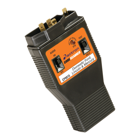
CODE SCANNER
Para Nombre, Domicilio y Telefono
del Importador: Ver Empaque
AUDIO
ON
OFF
Domestic Ford,
CP9015
Lincoln & Mercury
1
¨
TEST
STO
HOLD
CP9015
Advertisement
Table of Contents

Related Manuals for Actron Code Scanner CP9015


Summary of Contents for Actron Code Scanner CP9015
- Page 1 precision electronic solutions CODE SCANNER ¨ FAVOR DE LEER INSTRUCTCTIVO ANTES DE USAR EL ARTICULO Car Computer Code Reader Domestic Ford, Lincoln, Mercury with EEC-IV or AUDIO MCU Engine Computer TEST Control Systems Lector de Códigos de Computadoras HOLD Domestic Ford, de Automóvil CP9015 Lincoln &...
- Page 3 .. 3 computers. Your Actron Code Scanner is made by Actron, the largest and most 2 Code Scanner Basics: When do trusted name in automotive diagnostic you use it and what does it do? ..5 equipment for the home mechanic.
- Page 4 • Always wear approved eye protection. • Always operate the vehicle in a well ventilated area. Do not inhale exhaust gases – they are very poisonous! • Always keep yourself, tools and test equipment away from all moving or hot engine parts. •...
- Page 5 Trouble codes indicate used these tests for years. Now you can problems found by the computer. do the same thing by using the Actron Code Scanner tool! • Repair the vehicle yourself using trouble codes to help pinpoint the problem.
- Page 6 Trouble codes give you valuable trouble codes are and where they come knowledge – whether you go for from, you are well on your way to fixing professional vehicle servicing or “do-it- today’s computer controlled vehicles! yourself. ” Now that you know what The following is a list of publishers who have manuals containing trouble code repair procedures and related information.
- Page 7 Use the Code Scanner: • When you experience a driveability problem with your vehicle. AUDIO • When the “Check Engine” light comes ® on (if used on vehicle). • For a routine system check – even on HOLD CP9015 – Ford, Lincoln & Mercury vehicles with a “Check Engine”...
- Page 8 A 9 volt transistor radio battery (NEDA Do the following: 1604) is required to power the Code 1) Put the Hold/Test switch in TEST Scanner. Either a regular or alkaline position. battery may be used. The Code Scanner has an automatic battery shut- off when not in use.
- Page 9 You can tell which computer system is in The Code Scanner plugs into the your vehicle by noting which connector vehicle “Self-Test” connector which is type is installed! located in the engine compartment. The connectors are located in one of six •...
- Page 10 Complete Description for Reading and Using Service Codes. This section shows you how to use the The Self-Test procedure (also called Code Scanner for: “Quick Test”) involves engine off and engine running tests. The entire • Running tests of the engine computer procedure is summarized in the chart.
- Page 11 1) Safety First! • Inspect wiring for: • Set the parking brake. – Contact with sharp edges. (This happens often.) • Put shift lever in PARK (automatic transmission) or NEUTRAL (manual – Contact with transmission). hot surfaces, such as • Block the drive wheels. exhaust •...
- Page 12 6) Have a Pencil • Turn ignition key to OFF position. and Paper WARNING: Always operate vehicle Ready. in a well ventilated area. • This is for Do NOT inhale exhaust gases – they writing down are very poisonous! all the codes. 4) Check Code Scanner Battery.
- Page 13 IMPORTANT: You must complete all steps in Self-Test Part 1 before proceeding to Part 2. Verify good battery in Code Scanner (Section 2). 1) Verify 5) Get Codes from the Flashing STO Ignition Light. Key is in NOTE: If the light does not flash, go back and repeat SELF-TEST PART 2 Position.
- Page 14 single flash (called a “separator • Code sequence example with code”) KOEO codes = 21 and 32, Continuous Memory code =14: • The first code group has KOEO (Key On Engine Off) codes – for PAUSE problems which are present now. Some service manuals call these FLASH FLASH (pause) FLASH “hard”...
- Page 15 • Write down codes in the order they are sent. 6) Turn Ignition Key to OFF Position. At this point you can either: • Have your vehicle professionally serviced. Codes indicate problems found by the computer. • Repair the vehicle yourself using service codes to help pinpoint the problem. Refer to Test Results Chart.
- Page 16 manual for troubleshooting charts HVAC/ CRUISE related to the symptom. STER BRAKE BOOSTER FUEL TO TRANS PRESS . .. MODE .S.A. AUDIO 4) Put Code TEST FRONT Scanner OF CAR ® 9RAC2LAB HOLD/TEST HOLD This portion of Switch in CP9015 – Ford, Lincoln & Mercury Domestic 1981&...
- Page 17 4) Start the Engine. (See page 14 for 1991 & older vehicles.) • Only use the ignition key to 1) Turn Ignition Key OFF. start engine – do not use a • Wait 10 seconds before proceeding. remote starter. • If engine will not start, stalls or runs 2) Turn off Electrical Loads.
- Page 18 IMPORTANT: You must complete all steps in Self-Test Parts 1,2 and 3 before proceeding to Part 4. Verify good battery in Code Scanner (Section 2). 1) Verify Ignition Key is in OFF 7) Get Engine Identification (ID) Code Position. from the Flashing STO Light. NOTE: If the light does not flash, go back and repeat SELF-TEST PART 4 2) Put Code Scanner HOLD/TEST...
- Page 19 • Perform a brief Wide-Open-Throttle Running) codes are sent as a (WOT) action right after the Dynamic group. Response — The KOER group will always signal. contain at least one code. This will (Completely be a “system pass” code (11 or 111) press and if no problems are seen.
- Page 20 DYNAMIC ENGINE ENGINE RESPONSE RUNNING ID CODE CODE CODE ACTION TO TAKE: 2,3,4 or 5 No problems found by computer during KOER Self- (or 111) Test, however… •If Continuous Memory codes were obtained in Self-Test Part 2, go to SELF-TEST PART 5: Evaluate “Continuous Memory”...
- Page 21 4) If any codes remain, refer to vehicle service manual for Continuous Memory code troubleshooting charts Do this Part if “Continuous Memory” and repair procedures. codes (other than an 11 or 111 pass code) were received during SELF-TEST 5) Erase Continuous Memory codes PART 2: Key On Engine Off (KOEO) after all repairs have been made.
- Page 22 Code Definitions for FORD Engines with EEC-IV Computer System (Electronic Engine Control system, 4) Incorrect information version IV) from a sensor may RPM too low during Engine Run Self-Test (lean fuel cause the computer to test). control the engine in the wrong way.
- Page 23 signal voltage too high Electronic Distributorless during normal engine run Engine Coolant Ignition System (EDIS) fault operation. Temperature (ECT) sensor – failure in coil 3 primary signal voltage: out of range circuit. RPM too low to perform (Key On Engine Off Self- EGR test (Engine Run Self- Test), not at normal Distributorless Ignition...
- Page 24 Vane AIr Flow (VAF) Electronic 4-Speed sensor – voltage signal is Overdrive Automatic Engine control system too low. Transaxle (E4OD): never went into closed loop Transmission Oil fuel operation. Transaxle problem – 4x4L Temperature (TOT) sensor switch is closed. – signal voltage is too high. Transaxle problem –...
- Page 25 Supercharger Bypass Exhaust Heat Control Solenoid (SBS): circuit (EHC) solenoid – circuit Insufficient manifold failure. failure. vacuum change detected during Dynamic Response portion of Engine Run Self- High Speed Electro-Drive Exhaust Gas Oxygen (EGO) Test. Fan (HEDF) – circuit failure. sensor –...
- Page 26 Right side Exhaust Gas Air Charge Temperature Certain 1991 and newer Oxygen (EGO) sensor – (ACT) sensor – signal vehicles use 3 digit codes signal voltage indicates voltage is too high. “rich” during “lean” air/fuel to report the results of conditions.
- Page 27 Heated Exhaust Gas “Downstream” Heated Mass Air Flow (MAF) Oxygen (HEGO) sensor – Exhaust Gas Oxygen sensor – signal voltage is voltage signal not switching (HEGO) sensor – signal lower than expected. during Engine Run Self- voltage too low. Test. Indicates “lean” (Bank Injector pulsewidth higher #2).
- Page 28 Ignition system (distributor- Ignition system Thermactor Air System less) problem – Coil #2 (distributorless) problem – problem – air flow not primary side circuit failure. Coil #4 primary side circuit bypassed (vented to failure. atmosphere) during Engine Run Self-Test. Ignition system (distributor- less) problem –...
- Page 29 Engine Coolant Vehicle transmission not in Idle Air Control (IAC) Temperature (ECT) sensor PARK during Key On solenoid – circuit failure. – signal voltage higher than Engine Off Self-Test. expected. Thermactor Air Bypass Low Speed Fuel Pump – (TAB or AM-1) solenoid: Octane Adjust service pin open circuit failure between circuit failure.
- Page 30 High Speed Electro-Drive Electronic Pressure Control Shift Solenoid 3 (SS3) – Fan (HEDF) – operation (EPC) solenoid – circuit circuit failure. not detected during Key On failure. Engine Off Self-Test. Shift Solenoid #4 (SS4) – Electronic Pressure Control circuit failure. Variable Control Relay (EPC) solenoid –...
- Page 31 Manual Lever Position (MLP) sensor – signal voltage too low. Manual Lever Position (MLP) sensor – signal voltage too high. Manual Lever Position (MLP) sensor – signal voltage out of range. Transmission problem – mechanical failure in first gear and reverse. Transmission problem –...
- Page 33 5) Put Hold/Test Switch in HOLD Service manuals call this the “Output Position State Check.” You can turn on most of the computer controlled relays and solenoids except the fuel pump relay and 6) Turn Ignition fuel injectors. This is helpful for checking Key to ON voltages, relay operation, etc.
- Page 34 • Throttle action may repeated as often as desired to turn the actuators on and off. NOTE: If vehicle is equipped with Integrated Vehicle Speed Control (IVSC), disconnect vacuum supply hose from the Speed Control Servo (to release stored vacuum). Otherwise, the Speed Control Solenoids will energize the first time the throttle is depressed...
- Page 35 This test is only used on vehicles with 7) Start the Engine Sequential electronic Fuel Injection • Stay away from moving parts. (SFI) engines. (Where the injectors are fired individually in the same sequence as the spark plug firing sequence.) The 8) Put Hold/Test Switch in TEST test turns each injector on and off and Position...
- Page 36 12) Optional Retest - 1987 & Newer can tell you how weak a bad cylinder is. (The computer alters • Lightly press and release throttle inspection during retest.) Test within 2 minutes after the last code results will be different for a good, is sent.
- Page 37 • This test can help locate intermittent 8) Depending upon Vehicle Model faults in SOME circuits (see chart on Year..page 36). • 1986 & Older: “Wiggle Test” is now • When Wiggle test is activated, the activated! Go to Step 9. Code Scanner STO light and Audio •...
- Page 38 ACT ....1984 & up BP ....1984 & up ECT ..... 1984 & up EGO ..... 1990 & up EVP ..... 1984 & up IDM ....1990 & up (DIS or dual plug DIS only) ITS ....1990 & up MAF .....
- Page 39 This section shows you how to use the Code Scanner for: • Safety First! Follow all safety rules. • Running tests of the engine computer • Perform Visual Inspection. This often system. reveals the problem. • Reading service codes to pinpoint •...
- Page 40 recently? Sometimes things get not wipe off! Obtain extra grease, if reconnected in the wrong place, or needed, from your vehicle dealer. It is not at all. a special type for this purpose. Repair any problems found during the visual •...
- Page 41 4) Plug the Code Scanner into the V-6 and V-8 engines. Vehicle Self-Test Connector. • Refer to Section 3, “Connector Location”. (The Self-Test connector is near the MCU computer module.) Not used in systems Remove PCV valve from breather cap on valve cover.
- Page 42 4.2L and 5.8L engines with a vacuum delay valve. There is a tee with a restrictor in the Thermactor Vacuum control line. The restrictor must be uncapped during the test. Replace the cap after testing. Refer to drawing for location of restrictor on the TAD vacuum line (4.2L engines) or the TAB vacuum line (5.8L engines).
- Page 43 1) Verify: • All codes are 2 digits long. Ignition Key is in OFF Position and • The pause between each digit is 2 Code Scanner is Connected. seconds. • After all codes are sent, the whole group is sent again just one more 2) Put Code Scanner HOLD/TEST time (so you can double check your Switch in TEST Position.
- Page 44 • Have your vehicle professionally serviced. Codes indicate problems found by the computer. • Repair the vehicle yourself using service codes to help pinpoint the problem. Refer to Test Results Chart. KOEO CODES ACTION TO TAKE: System pass. No problem found by computer during KOEO Self- (all except Test.
- Page 45 • Count flashes on the STO light. (Ignore any flashes lasting longer (Refer to page 44 for V-6 & V-8 than 1 second.) engines.) – 4 cylinder: 2 Flashes. – 6 cylinder: 3 Flashes. 1) Verify: Note: If the light does not flash or •...
- Page 46 Example of code series 12 and 42: • Block the drive wheels. • Stay away from moving engine PAUSE parts. FLASH (pause) FLASH FLASH (longer pause) 2) Start the Engine. PAUSE 3) Warm-Up Engine. FLASH FLASH FLASH FLASH (pause) • Allow engine to idle until it reaches FLASH FLASH normal operating temperature.
- Page 47 – Tap on 8) Turn Ignition Key to OFF Position. end of exten- 9) Remove Code Scanner. sion with a light (4 At this point you can either: oz.) • Have your vehicle professionally hammer for 15 seconds. serviced. Codes indicate problems –...
- Page 48 KOER CODES ACTION TO TAKE: System pass. No problem found by computer during KOER Self- (all except Test. The Self-Test Diagnostic Procedure is complete. If vehicle high altitude) symptoms are still present, they are probably not related to the computer system. System pass.
- Page 49 manifold). “High Altitude” computer Thermactor adjusted for operation at • Many of the codes Air System unable to high elevations such as in bypass air (vent to Denver, Colorado. listed may not apply to atmosphere). (All except High your vehicle. Altitude): System pass.
- Page 50 Mid Vacuum Switch circuit is open. circuit is always open. (High Altitude only): Mid Vacuum Switch System pass. circuit is always open. Wide Open Throttle Closed Throttle (WOT) Vacuum Switch Vacuum Switch circuit is circuit is always closed. always open. CROWD Vacuum Switch circuit is always closed.
- Page 51 This section explains the EEC-IV engine A computer controlled engine is basically computer control system, the types of the same as earlier types. It is still an sensors and how the computer controls internal combustion engine with pistons, fuel delivery, idle speed, spark timing spark plugs, valves and cams.
- Page 52 OFF (no voltage signal to the computer). Switches connect to two wires and tell the computer simple things, such as whether or not the air conditioner is running. E C A • Signal Generator – These create their own signal to tell the BRAINS OF THE computer of some condition, such COMPUTER...
- Page 53 is. Sensors used: coolant tempera- amount of fuel delivered and the ture, throttle position, manifold computer would not know it. absolute pressure, mass air flow, RPM. • ...how much air is coming into the “Closed Loop” operation engine. Sensors used: mass air flow or a combination of manifold absolute The computer watches the coolant pressure, manifold air temperature,...
- Page 54 sensors to determine vehicle speed, engine load and temperature. (RPM, throttle position, coolant temperature Throttle position and RPM sensors tell and manifold pressure or mass air flow the computer when the vehicle is idling. sensors are used.) Then, the computer (Sometimes an idle position switch on the adjusts timing according to factory throttle is used.) The computer merely...
- Page 55 How MCU measures Throttle Position • Some MCU systems use an Idle The Reference Glossary describes the Tracking Switch. This is an electrical various sensors and actuators used in switch mounted near the throttle the EEC-IV and MCU systems. You can linkage on the carburetor.
- Page 56 an electric motor (“Feedback mixture to deliver. Carburetor Actuator”) to position this rod. • Another method uses a fuel metering The MCU system does not control idle rod positioned by vacuum. The speed – a standard mechanical idle cam computer controls vacuum to this rod mechanism is used.
- Page 57 Air conditioner Cylinder Identification signal. Canister Purge solenoid. This is a frequency type This device controls the signal coming from a flow of fuel vapors from the Air Conditioner Clutch camshaft mounted sensor. canister to the intake signal. This tells the ECA The ECA uses this signal to manifold.
- Page 58 information when controlling fuel delivery, Thermactor Air A term applied to frequency Digital Volt Meter. An instru- System, spark retard, signals – those which are ment using a numeric read- throttle kicker and canister constantly switching out to display measured purge.
- Page 59 Electro-Drive Fan relay. Exhaust Gas Oxygen Exhaust Heat Control The ECA energizes this sensor. The EGO sensor is solenoid. The ECA relay to apply power to the threaded into the exhaust energizes this solenoid to Electro-Drive Fan (mounted manifold, directly into the apply vacuum (and thus in front stream of the exhaust...
- Page 60 Feedback Carburetor. This The frequency of an High-speed Electro-Drive is used on early versions of electronic signal is a Fan relay. The ECA computer controlled measure of how often the energizes this relay when it engines. It is a carburetor signal repeats a voltage determines extra engine which can have its air/fuel...
- Page 61 Idle Speed Control. This Keep Alive Power. A power Mass Air Flow sensor. This refers to a small electric connection running from sensor measures the stepper motor mounted on the ECA directly to the amount of air entering the the throttle body and vehicle battery.
- Page 62 know it. Neutral Drive Switch. Used Power Steering Pressure on vehicles with automatic Electrical signals sent from Switch. This tells the ECA transmissions. The ECA the ECA. These signals when power steering is uses this switch to may activate relays or being used.
- Page 63 Sequential Fuel Injection or A special type of electric Sequential Electronic Fuel motor with a shaft that The connector that the Injection. A fuel injection rotates in small “steps” Code Scanner plugs into system using one injector instead of a continuous for testing purposes.
- Page 64 Thick Film Ignition system, A resistor whose resistance Transmission Temperature version 4. An ignition changes with temperature. Switch. Sends a system consisting of a Thermistors are used as temperature status signal distributor, ignition coil and sensors for vehicle coolant to the ECA. TFI-IV module.
- Page 65 Variable Control Relay Wide-open-throttle Air Module. Contains conditioner Cut-off relay. electronic switches to Used by the ECA to turn off control power to A/C clutch, the A/C clutch and thus engine cooling fan, fuel reduce engine loading. This pump, etc. ECA controls is desirable during heavy module.
- Page 66 No warranty (expressed or implied) can be made for its accuracy or completeness, nor is any responsibility assumed by Actron or anyone connected with it for loss or damages suffered through reliance on any information contained in this manual or misuse of accompanying product.