Advertisement
SERVICE MANUAL
Ver. 1.1 2007. 04
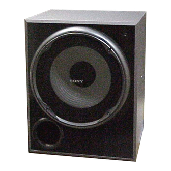
• SA-WP16 is the sub woofer section
in HT-DDW1600.
Speaker system
Active sub woofer,
magnetically shielded
Speaker unit
250 mm cone type
Enclosure type
Acoustically loaded bass
reflex
1)
RMS output
200 W
175 W
2)
Input
LINE IN (input pin jacks)
1)
Measured under the following conditions:
Area code
Power requirements
AUS, E51, MY, SP, TH 240 V AC, 50 Hz
MX
127 V AC, 60 Hz
AR
230 V AC, 50 Hz
2)
Measured under the following conditions:
Area code
Power requirements
AR
220 V AC, 50 Hz
Sony Corporation
9-887-571-02
Home Audio Division
2007D04-1
Published by Sony Techno Create Corporation
© 2007. 04
SA-WP16
SPECIFICATIONS
Power requirements
Area code
MY, SP, TH
AUS
MX
E51
AR
Power consumption
Dimensions (width/height/depth) (Approx.)
Mass (Approx.)
Design and specifications are subject to change without
notice.
• Abbreviation
AR : Argentina model
AUS : Australian model
SP
: Singapore model
TH : Thai model
E51 : Chilean and Peruvian model
MX : Mexican model
MY : Malaysia model
E Model
Australian Model
Power requirements
230 – 240 V AC,
50/60 Hz
240 V AC, 50 Hz
127 V AC, 60 Hz
120/220/240 V AC,
50/60 Hz
220 – 230 V AC,
50/60 Hz
80 W
335 × 410 × 412 mm
(Including front panel)
10.6 kg
ACTIVE SUBWOOFER
Advertisement
Table of Contents

Related Manuals for Sony SA-WP16


Summary of Contents for Sony SA-WP16
- Page 1 SA-WP16 SERVICE MANUAL E Model Australian Model Ver. 1.1 2007. 04 • SA-WP16 is the sub woofer section in HT-DDW1600. SPECIFICATIONS Speaker system Active sub woofer, Power requirements magnetically shielded Area code Power requirements Speaker unit 250 mm cone type MY, SP, TH 230 –...
-
Page 2: Service Notes
COMPONENTS IDENTIFIED BY MARK 0 OR DOTTED LINE WITH MARK 0 ON THE SCHEMATIC DIAGRAMS AND IN THE PARTS LIST ARE CRITICAL TO SAFE OPERATION. REPLACE THESE COMPONENTS WITH SONY PARTS WHOSE PART NUMBERS APPEAR AS SHOWN IN THIS MANUAL OR IN SUPPLEMENTS PUBLISHED BY SONY. - Page 3 SA-WP16 Ver. 1.1 SECTION 1 DIAGRAMS • NOTE FOR PRINTED WIRING BOARDS AND SCHEMATIC DIAGRAMS 1-1. CIRCUIT BOARDS LOCATION THIS NOTE IS COMMON FOR PRINTED WIRING BOARDS AND SCHEMATIC DIAGRAMS. (In addition to this, the necessary note is INPUT CONTROL board printed in each block.)
- Page 4 SA-WP16 Ver. 1.1 1-2. PRINTED WIRING BOARDS — MAIN SECTION — • Refer to page 3 for Circuit Boards Location. : Uses unleaded solder. • Semiconductor Location Ref. No. Location D101 C-12 D102 C-13 D303 D-13 RV801 D304 D-13 LEVEL...
- Page 5 SA-WP16 Ver. 1.1 1-3. SCHEMATIC DIAGRAM — MAIN SECTION — • Refer to page 6 for IC Block Diagram. R209 Q102 IC202(1/2) C203 R208 C201 R202 R123 C204 C120 R210 CNP801 CN201 C127 IC202(2/2) D101 J101 R207 R205 R206 R211...
- Page 6 SA-WP16 • IC BLOCK DIAGRAM IC500 µPC1237C-A (MAIN Board) OFF AC RESET DETECT DC LOAD OVER SWITCH FOR OVERLOAD LATCH/AUTOMATIC DETECTOR RESET OUTPUT AC-OFF OFFSET DETECTOR DETECTOR FLIP-FLOP OUTPUT OUTPUT OFFSET OFFSET DETECTOR DETECTOR DRIVER OFF AC RELAY SA-WP16...
-
Page 7: Section 2 Exploded Views
SA-WP16 Ver. 1.1 SECTION 2 EXPLODED VIEWS NOTE: • The mechanical parts with no reference • -XX and -X mean standardized parts, so The components identified by mark 0 or dotted line with mark number in the exploded views are not supplied. -
Page 8: Rear Section
SA-WP16 Ver. 1.1 2-2. REAR SECTION supplied with RV801 Q307 not supplied Q308 not supplied (TRANS board) F901 F900 not supplied (INPUT CONTROL board) F902 not supplied not supplied not supplied (SWITCH board) not supplied not supplied Ref. No. Part No. -
Page 9: Section 3 Electrical Parts List
SA-WP16 Ver. 1.1 SECTION 3 INPUT COTROL MAIN ELECTRICAL PARTS LIST NOTE: • Due to standardization, replacements in • Items marked “*” are not stocked since The components identified by mark 0 or dotted line with mark the parts list may be different from the they are seldom required for routine service. -
Page 10: Main Switch
SA-WP16 Ver. 1.1 MAIN SWITCH Ref. No. Part No. Description Remark Ref. No. Part No. Description Remark CN301 1-564-320-00 PIN, CONNECTOR (3.96mm PITCH) 2P R212 1-249-428-11 CARBON 8.2K 1/4W CN402 1-785-104-11 PIN, CONNECTOR (3.96mm PITCH) 6P R213 1-249-428-11 CARBON 8.2K... - Page 11 SA-WP16 Ver. 1.1 SWITCH TRANS Ref. No. Part No. Description Remark < CONNECTOR > * CN3 1-695-044-11 PIN, CONNECTOR (3.96mm PITCH) 2P * CN20 1-695-044-11 PIN, CONNECTOR (3.96mm PITCH) 2P < SWITCH > 0 S901 1-572-267-51 SWITCH, PUSH (AC POWER) (1 KEY) (POWER)
-
Page 12: Revision History
SA-WP16 REVISION HISTORY Clicking the version allows you to jump to the revised page. Also, clicking the version at the upper on the revised page allows you to jump to the next revised page. Ver. Date Description of Revision 2007. 02 2007.