Asus P4S800-MX User Manual
P4s800-mx english user manual e1447
Hide thumbs
Also See for P4S800-MX:
- User manual (84 pages) ,
- Manuel (64 pages) ,
- Guide utilisateur (88 pages)
Table of Contents
Advertisement
Quick Links
Advertisement
Table of Contents

Related Manuals for Asus P4S800-MX


Summary of Contents for Asus P4S800-MX
- Page 1 P4S800-MX User Guide...
- Page 2 Product warranty or service will not be extended if: (1) the product is repaired, modified or altered, unless such repair, modification of alteration is authorized in writing by ASUS; or (2) the serial number of the product is defaced or missing.
-
Page 3: Table Of Contents
Notices .................... v Safety information ................vi P4S800-MX specification summary ..........vii About this guide ................viii Chapter 1: Product introduction 1.1 Welcome! ................1-2 1.2 Package contents ............... 1-2 1.3 Special features ..............1-2 1.4 Before you proceed ............1-5 Onboard LED .............. - Page 4 2.1 Managing and updating your BIOS ........2-2 2.1.1 Creating a bootable floppy disk ......2-2 2.1.2 Using ASUS EZ Flash to update the BIOS .... 2-3 2.1.3 Using the AFLASH utility ........2-4 2.1.3 Recovering the BIOS with CrashFree BIOS ..2-6 2.1.4...
-
Page 5: Federal Communications Commission Statement
Federal Communications Commission Statement This device complies with FCC Rules Part 15. Operation is subject to the following two conditions: • This device may not cause harmful interference, and • This device must accept any interference received including interference that may cause undesired operation. This equipment has been tested and found to comply with the limits for a Class B digital device, pursuant to Part 15 of the FCC Rules. -
Page 6: Electrical Safety
Electrical safety • To prevent electrical shock hazard, disconnect the power cable from the electrical outlet before relocating the system. • When adding or removing devices to or from the system, ensure that the power cables for the devices are unplugged before the signal cables are connected. -
Page 7: Special Features
Socket 478 for Intel ® Pentium ® 4 Northwood/Willamette processor ® Intel Hyper-Threading technology ready ® New power design for next generation Intel Prescott CPU Chipset SiS661 FX SiS963L Front Side Bus (FSB) 800/533/400 MHz Memory 2 x 184-pin DDR DIMM sockets for up to 2GB memory Supports PC3200/2700/2100 unbuffered non-ECC DDR DIMMs. -
Page 8: Conventions Used In This Guide
BIOS features 2Mb Flash EEPROM, DMI, PnP features, SM BIOS 2.3, WfM 2.0, ASUS CrashFree BIOS, ASUS EZ Flash, and ASUS C.P.U. (CPU Parameter Recall) Industry standard PCI 2.2, USB 2.0/1.1 Manageability WOL/WOR by PME, Wake on USB KB/Mouse Form Factor Micro-ATX form factor: 9.6 in x 9.6 in (24.5 cm x 24.5 cm) -
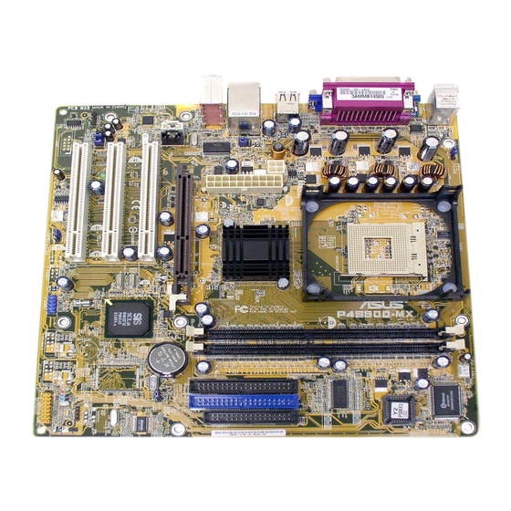
Page 9: Product Introduction
This chapter describes the features of the motherboard. It includes brief descriptions of the motherboard components, and illustrations of the layout, jumper settings, and connectors. Product introduction... - Page 10 ® Thank you for buying the ASUS P4S800-MX motherboard! The ASUS P4S800-MX motherboard delivers a host of new features and latest technologies making it another standout in the long line of ASUS quality motherboards! Before you start installing the motherboard, and hardware devices on it, check the items in your package with the list below.
- Page 11 DLS2 MIDI synthesizer with Yamaha DLSbyXG sound set, 5.1 Virtual Theater™ and supports all major game audio technologies including Microsoft DirectX™8.0, Microsoft DirectSound 3D™, A3D, MacroFX, ZoomFX, MultiDrive 5.1 and EAX. See page 1-17. ASUS P4S800-MX motherboard user guide...
-
Page 12: Asus Crashfree Bios
See page 2-6. ASUS EZ Flash BIOS With the ASUS EZ Flash, you can easily update the system BIOS even before loading the operating system. No need to use a DOS-based utility or boot from a floppy disk. See page 2-3. -
Page 13: Onboard Led
The illustration below shows the location of the onboard LED. SB_PWR1 Standby Powered Power P4S800-MX Onboard LED ASUS P4S800-MX motherboard user guide... -
Page 14: Motherboard Layout
1.5.1 Motherboard layout KBPWR1 24.5cm (9.6in) +5VSB KBPWR1 CPU_FAN1 (Default) PS/2KBMS T: Mouse B: Keyboard Super COM1 Socket 478 USBPW12 USBPW34 VGA1 USB1 USB2 +5VSB (Default) ATX12V1 USB2.0 661FX Top: T: USB3 RJ-45 North Bridge B: USB4 Top:Line In Center:Line Out Below:Mic In CR2032 3V Accelerated Graphics Port (AGP1) -
Page 15: Placement Direction
Place eight (8) screws into the holes indicated by circles to secure the motherboard to the chassis. Do not overtighten the screws! Doing so may damage the motherboard. Place this side towards the rear of the chassis ASUS P4S800-MX motherboard user guide... -
Page 16: Overview
1.6.1 Overview ® ® The Intel Pentium 4 processor has a gold triangular mark on one corner. This mark indicates the processor Pin 1 that should match a specific corner of the CPU socket. Gold Arrow P4S800-MX Socket 478 Incorrect installation of the CPU into the socket may bend the pins and severely damage the CPU! ®... -
Page 17: Installing The Cpu
The lever clicks on the side tab to indicate that it is locked. 6. Install a CPU heatsink and fan following the instructions that came with the heatsink package. 7. Connect the CPU fan cable to the CPU_FAN1 connector on the motherboard. ASUS P4S800-MX motherboard user guide... -
Page 18: Dimm Sockets Location
You may install 64MB, 128MB, 256MB, 512MB, and 1GB DDR DIMMs into the DIMM sockets. Obtain DDR DIMMs only from ASUS qualified vendors. Refer to the Qualified DDR400 vendors list next page. Visit the ASUS website (www.asus.com) for the latest DDR Qualified Vendors List. -
Page 19: Installing A Dimm
DIMM is properly Unlocked seated. Retaining Clip A DDR DIMM is keyed with a notch so that it fits in only one direction. DO NOT force a DIMM into a socket to avoid damaging the DIMM. ASUS P4S800-MX motherboard user guide 1-11... -
Page 20: Installing An Expansion Card
In the future, you may need to install expansion cards. The following sub-sections describe the slots and the expansion cards that they support. Make sure to unplug the power cord before adding or removing expansion cards. Failure to do so may cause you physical injury and damage motherboard components. -
Page 21: Standard Interrupt Assignments
When using PCI cards on shared slots, ensure that the drivers support “Share IRQ” or that the cards do not need IRQ assignments. Otherwise, conflicts will arise between the two PCI groups, making the system unstable and the card inoperable. ASUS P4S800-MX motherboard user guide 1-13... -
Page 22: Pci Slots
1.8.3 PCI slots The PCI slots support PCI cards such as a LAN card, SCSI card, USB card, and other cards that comply with PCI specifications. 1.8.4 AGP slot The Accelerated Graphics Port (AGP) slot that supports AGP 8X/4X (+1.5V) cards. When you buy an AGP card, make sure that you ask for one with +1.5V specification. -
Page 23: Jumpers
Except when clearing the RTC RAM, never remove the cap on CLRTC1 jumper default position. Removing the cap will cause system boot failure! CLRTC1 Normal Clear CMOS (Default) P4S800-MX Clear RTC RAM ASUS P4S800-MX motherboard user guide 1-15... - Page 24 2. USB device wake-up (3-pin USBPW12, USBPW34, USBPW56) Set these jumpers to +5V to wake up the computer from S1 sleep mode (CPU stopped, DRAM refreshed, system running in low power mode) using the connected USB devices. Set to +5VSB to wake up from S3 sleep mode (no power to CPU, DRAM in slow refresh, power supply in reduced power mode).
-
Page 25: Connectors
9. VGA port. This port connects a VGA compatible monitor. 10. Serial port. This 9-pin COM port is for pointing devices or other serial devices. 11. PS/2 keyboard port. This purple connector is for a PS/2 keyboard. ASUS P4S800-MX motherboard user guide 1-17... -
Page 26: Internal Connectors
1.10.2 Internal connectors 1. IDE connectors (40-1 pin PRI_IDE1, SEC_IDE1) This connector supports the provided UltraATA133 IDE hard disk ribbon cable. Connect the cable’s blue connector to the primary (recommended) or secondary IDE connector, then connect the gray connector to the UltraATA133 slave device (hard disk drive) and the black connector to the UltraATA133 master device. - Page 27 Be default, the pins labeled LINE OUT_R/BLINE_OUT_R and the pins LINE OUT_L/BLINE_OUT_L are shorted with jumper caps. Remove the caps only when you are connecting the front panel audio cable. FP_AUDIO1 P4S800-MX Front Panel Audio Connector ASUS P4S800-MX motherboard user guide 1-19...
- Page 28 5. CPU and chassis fan connectors (3-pin CPU_FAN1, CHA_FAN1) The fan connectors support cooling fans of 350mA~740mA (8.88W max.) or a total of 1A~2.22A (26.64W max.) at +12V. Connect the fan cables to the fan connectors on the motherboard, making sure that the black wire of each cable matches the ground pin of the connector.
- Page 29 These connectors allow you to receive stereo audio input from sound sources such as a CD-ROM, TV tuner, or MPEG card. AUX1 (White) CD1 (Black) Left Audio Channel Ground Ground Right Audio Channel P4S800-MX Internal Audio Connectors ASUS P4S800-MX motherboard user guide 1-21...
- Page 30 9. Speaker out connector (4-pin SPEAK1) This connector connects to the case-mounted speaker and allows you to hear system beeps and warnings. SPEAKER1 P4S800-MX Speaker Out Connector 10. GAME/MIDI connector (16-1 pin GAME1) This connector supports a GAME/MIDI module. Connect the GAME/MIDI cable with yellow connector to the yellow header onboard.
- Page 31 If your motherboard package comes with a 2-pin to 3-pin power LED converter, connect the 2-pin plug to this connector, and the other end to the 3-pin power LED plug from the system chassis. ASUS P4S800-MX motherboard user guide 1-23...
- Page 32 • Power Switch / Soft-Off Switch Lead (2-pin PWR_BTN) This connector connects a switch that controls the system power. Pressing the power switch turns the system between ON and SLEEP, or ON and SOFT OFF, depending on the BIOS or OS settings. Pressing the power switch while in the ON mode for more than 4 seconds turns the system OFF.
-
Page 33: Chapter 2: Bios Information
This chapter tells how to change system settings through the BIOS Setup menus. Detailed descriptions of the BIOS parameters are also provided. BIOS information... -
Page 34: Creating A Bootable Floppy Disk
BIOS in the future. Copy the original motherboard BIOS using the ASUS Update or AFLASH utilities. Visit the ASUS website and download the latest BIOS file for this motherboard using the ASUS Update utility. -
Page 35: Using Asus Ez Flash To Update The Bios
If the correct BIOS file is not found in the floppy disk, the error message “P4S800MX.BIN not found!” 4. Insert the floppy disk that contains the BIOS file. If the P4S800MX.BIN file is found in the floppy disk, EZ Flash performs the BIOS update process and automatically reboots the system when done. -
Page 36: Using The Aflash Utility
2.1.3 Using the AFLASH utility AFLASH is a Flash Memory Writer utility that allows you to update the BIOS using a bootable floppy disk, or copy the original motherboard BIOS. This utility only works in DOS mode. Copying the original motherboard BIOS To copy the original motherboard BIOS file: 1. -
Page 37: Updating The Bios
To update the BIOS: 1. Download an updated BIOS file from the ASUS website (www.asus.com) and save the file to the bootable floppy disk you earlier . 2. Reboot the computer from the floppy disk. -
Page 38: Recovering The Bios With Crashfree Bios
BIOS file you saved to the boot disk. If the Flash Memory Writer utility is not able to successfully update a complete BIOS file, the system may not boot. If this happens, call the ASUS Technical Support for assistance. -
Page 39: Asus Update
4. When the BIOS update process is complete, reboot the system. 2.1.5 ASUS Update The ASUS Update is a utility that allows you to update the motherboard BIOS in Windows ® environment. This utility is available in the support CD that comes with the motherboard package. - Page 40 3. If you selected updating/ downloading from the Internet, select the ASUS FTP site nearest you to avoid network traffic, or choose Auto Select. Click Next. 4. From the FTP site, select the BIOS version that you wish to download.
-
Page 41: Bios Setup Program
Use this menu to exit the current menu or to exit the Setup program. To access the menu bar items, press the right or left arrow key on the keyboard until the desired item is highlighted. ASUS P4S800-MX motherboard user guide... -
Page 42: Legend Bar
2.2.2 Legend bar At the bottom of the Setup screen is a legend bar. The keys in the legend bar allow you to navigate through the various setup menus. The following table lists the keys found in the legend bar with their corresponding functions. Navigation Key(s) Function Description <F1>... - Page 43 Valid values for month, day, and year are Month: (1 to 12), Day: (1 to 31), Year: (up to 2099). Use the <Tab> or <Shift> + <Tab> keys to move between the month, day, and year fields. ASUS P4S800-MX motherboard user guide 2-11...
- Page 44 Legacy Diskette A [1.44M, 3.5 in.] Sets the type of floppy drive installed. Configuration options: [None] [360K, 5.25 in.] [1.2M , 5.25 in.] [720K , 3.5 in.] [1.44M, 3.5 in.] [2.88M, 3.5 in.] Floppy 3 Mode Support [Disabled] This is required to support older Japanese floppy drives. The Floppy 3 Mode feature allows reading and writing of 1.2MB (as opposed to 1.44MB) on a 3.5-inch diskette.
-
Page 45: Primary And Secondary Master/Slave
[User Type HDD] Manually enter the number of cylinders, heads and sectors per track for the drive. Refer to the drive documentation or on the drive label for this information. ASUS P4S800-MX motherboard user guide 2-13... - Page 46 After entering the IDE hard disk drive information into BIOS, use a disk utility, such as FDISK, to partition and format new IDE hard disk drives. This is necessary so that you can write or read data from the hard disk. Make sure to set the partition of the Primary IDE hard disk drives to active.
-
Page 47: Keyboard Features
[0] [1] [2] [3] [4] [5] [6] [Disabled] 2.3.2 Keyboard Features Boot Up NumLock Status [On] This field enables users to activate the Number Lock function upon system boot. Configuration options: [Off] [On] ASUS P4S800-MX motherboard user guide 2-15... - Page 48 Keyboard Auto-Repeat Rate [6/Sec] This controls the speed at which the system registers repeated keystrokes. Options range from 6 to 30 characters per second. Configuration options: [6/Sec] [8/Sec] [10/Sec] [12/Sec] [15/Sec] [20/Sec] [24/Sec] [30/Sec] Keyboard Auto-Repeat Delay [1/4 Sec] This field sets the time interval for displaying the first and second characters. Configuration options: [1/4 Sec] [1/2 Sec] [3/4 Sec] [1 Sec] CPU Speed [Manual] When the motherboard is set to JumperFree™...
- Page 49 OS/2 Onboard Memory > 64M [Disabled] When using OS/2 operating systems with installed DRAM of greater than 64MB, you need to set this option to [Enabled]. Otherwise, leave to the default setting [Disabled]. Configuration options: [Disabled] [Enabled] ASUS P4S800-MX motherboard user guide 2-17...
-
Page 50: Chip Configuration
2.4.1 Chip Configuration SDRAM Configuration [By SPD] This parameter allows you to set the optimal timings for items 2–5, depending on the memory modules that you are using. The default setting is [By SPD], which configures items 2–5 by reading the contents in the SPD (Serial Presence Detect) device. - Page 51 You can also set both channels to [Disabled]. Configuration options: [Both] [Primary] [Secondary] [Disabled] IDE Bus Master Support [Enabled] This item controls the IDE Bus Master support for non-Windows operating systems. Configuration options: [Enabled] [Disabled] ASUS P4S800-MX motherboard user guide 2-19...
-
Page 52: I/O Device Configuration
2.4.2 I/O Device Configuration Floppy Disk Access Control [R/W] When set to [Read Only], this parameter protects files from being copied to floppy disks by allowing reads from, but not writes to, the floppy disk drive. The default setting [R/W] allows both reads and writes. Configuration options: [R/W] [Read Only] Onboard Serial Port 1 [3F8H/IRQ4] This field allows you to set the addresses for the onboard serial connector. -
Page 53: Pci Configuration
This field allows you to select the primary graphics card. Configuration options: [PCI VGA Card] [AGP VGA Card] [Onboard VGA] USB Function [Enabled] This field allows you to enable or disable the USB function. Configuration options: [Enabled] [Disabled] ASUS P4S800-MX motherboard user guide 2-21... - Page 54 USB Function 2.0 [Enabled] This field allows you to enable or disable the USB 2.0 function. Configuration options: [Enabled] [Disabled] Onboard PCI Devices Control Onboard LAN [Enabled] This field allows you enable or disable the onboard LAN. Configuration options: [Enabled] [Disabled] Onboard LAN Boot ROM [Disabled] This field allows you enable or disable the onboard LAN Boot ROM feature.
-
Page 55: Power Menu
This field defines the video off features. The Display Power Management System (DPMS) feature allows the BIOS to control the video display card if it supports the DPMS feature. [Blank Screen] only blanks the screen. Use this for monitors without power management or “green” features. ASUS P4S800-MX motherboard user guide 2-23... -
Page 56: Power Up Control
Even if installed, your screen saver does not display when you select [Blank Screen] for the above field. [V/H SYNC+Blank] blanks the screen and turns off vertical and horizontal scanning. Configuration options: [Blank Screen] [V/H SYNC+Blank] [DPMS Standby] [DPMS Suspend] [DPMS OFF] [DPMS Reduce ON] HDD Power Down [Disabled] Shuts down any IDE hard disk drives in the system after a period of inactivity as set in this user-configurable field. -
Page 57: Hardware Monitor
[Everyday] [By Date] 2.5.2 Hardware Monitor CPU Temperature MB Temperature The onboard hardware monitor automatically detects and displays the motherboard and CPU temperatures. Select [Ignore] to disable the MB or CPU temperature auto-detect function. ASUS P4S800-MX motherboard user guide 2-25... -
Page 58: Boot Menu
CPU Fan Speed [xxxxRPM] or [N/A] Chassis Fan Speed [xxxxRPM] or [N/A] The onboard hardware monitor automatically detects and displays the CPU, chassis, and power fan speeds in rotations per minute (RPM). If any of the fans is not connected to the motherboard, the specific field shows N/A. VCORE Voltage, +3.3V Voltage, +5V Voltage, +12V Voltage The onboard hardware monitor automatically detects the voltage output through the onboard voltage regulators. - Page 59 The Advanced Programmable Interrupt Controller (APIC) setting allows you to distribute interrupt routings other than the 16 IRQs. The Programmable Interrupt Controller (PIC) setting allows you to use the 16 IRQs only. Configuration options: [APIC] [PIC] ASUS P4S800-MX motherboard user guide 2-27...
-
Page 60: Exit Menu
After configuring the BIOS save your changes and exit Setup. Select Exit from the menu bar to display the following menu. Pressing <Esc> does not immediately exit this menu. Select one of the options from this menu or <F10> from the legend bar to exit. Exit &... -
Page 61: Chapter 3: Software Support
This chapter describes the contents of the support CD that comes with the motherboard package. Software support... -
Page 62: Running The Support Cd
The contents of the support CD are subject to change at any time without notice. Visit the ASUS website for updates. 3.2.1 Running the support CD To begin using the support CD, simply insert the CD into your CD-ROM drive. The CD automatically displays the Drivers menu if Autorun is enabled in your computer. -
Page 63: Drivers Menu
ASUS PC Probe This smart utility monitors the fan speed, CPU temperature, and system voltages, and alerts you on any detected problems. This utility helps you keep your computer at a healthy operating condition. ASUS P4S800-MX motherboard user guide... -
Page 64: Asus Contact Information
Install ASUS Update This program allows you to download the latest version of the BIOS from the ASUS website. Before using the ASUS Update, make sure that you have an Internet connection so you can connect to the ASUS website. See page 2-7 for ASUS Update installation and use.