
Related Manuals for Acer Aspire 5710


Summary of Contents for Acer Aspire 5710
- Page 1 Aspire 5710/5710G/5310/5310G Series Service Guide Service guide files and updates are available on the ACER/CSD web; for more information, please refer to http://csd.acer.com.tw PRINTED IN TAIWAN...
-
Page 2: Revision History
Revision History Please refer to the table below for the updates made on Aspire 5710/5710G/5310/5310G Series service guide. Date Chapter Updates... - Page 3 Copyright Copyright © 2007 by Acer Incorporated. All rights reserved. No part of this publication may be reproduced, transmitted, transcribed, stored in a retrieval system, or translated into any language or computer language, in any form or by any means, electronic, mechanical, magnetic, optical, chemical, manual or otherwise, without the prior written permission of Acer Incorporated.
- Page 4 Conventions The following conventions are used in this manual: Denotes actual messages that appear SCREEN MESSAGES on screen. NOTE Gives bits and pieces of additional information related to the current topic. WARNING Alerts you to any damage that might result from doing or not doing specific actions.
- Page 5 DIFFERENT part number code to those given in the FRU list of this printed Service Guide. You MUST use the list provided by your regional Acer office to order FRU parts for repair and service of customer machines.
-
Page 7: System Specifications
• Up to 512 MB of DDR2 533 MHz memory, upgradeable to 2 GB using two soDIMM modules (dual- channel support) (AS5310) Display and graphics • 15.4" WXGA high-brightness (220-nits) Acer CrystalBrite™ TFT LCD, 1280 x 800 pixel resolution, supporting simultaneous multiwindow viewing via Acer GridVista™ •... -
Page 8: Input Devices
• 44.4W 4000 mAh Li-ion battery pack (6-cell) • 3-pin 65 W AC adaptor (for selected models) • 2.5-hour rapid charge system-off • 3.5-hour charge-in-use • 3-pin 90 W AC adapter supporting Acer QuicCharge™ technology: (for selected models) • 80% charge in 1 hour Chapter 1... -
Page 9: Options And Accessories
• Acer Empowering Technology (Acer eNet, ePower, eAudio, ePresentation, eDataSecurity, eLock, eRecovery, eSettings Management) NOTE: Models shipped with Windows Vista™ Starter Edition only support Acer eRecovery Management. • Acer Arcade™* • Acer Arcade Deluxe™* featuring DV Wizard, SportsCap, VideoMagician and DVDivine •... -
Page 10: System Compliance
• Operating: 20%~80% • Non-operating: 20%~80% System compliance • Wi-Fi • ACPI • Mobile PC 2002 • DMI 2.0 NOTE: The specifications listed above are for reference only. The exact configuration of your PC depends on the model purchased. Chapter 1... -
Page 11: System Block Diagram
System Block Diagram Chapter 1... -
Page 12: Board Layout
Board Layout Top View 2 3 4 2 3 4 LCD Connector Mainboard to Button Board Connector Speaker (Left) Connector JP36 Mainboard to LED Board Connector JP34 Speaker (Right) Connector PCI Express Card Socket Internal MIC Connector LED1 Power/Suspend LED South Bridge (ICH7M) LED2 Battery Charge/Discharge LED... -
Page 13: Bottom View
Bottom View 19 20 19 20 21 PJP1 DC-in Power Jack JP27 SATA HDD Connector PJP2 Battery Connector North Bridge (945GM/PM / 943GML) JP14 CRT Connector Volume Control JP25 ODD Connector JP28 DDRII Memory Socket JP19‘ Mini Card (TV-Tuner) Socket JP29 DDRII Memory Socket JP17... -
Page 14: Your Acer Notebook Tour
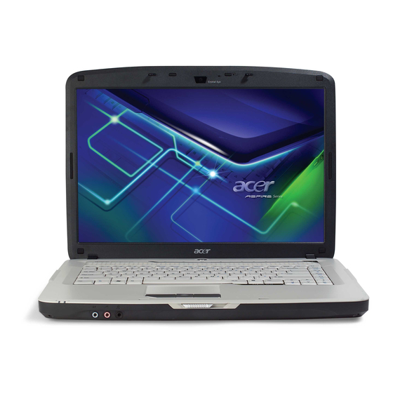
Acer Crystal Eye Web camera for video communication (for selected models). Power button Turns the computer on and off. Acer Arcade Launches the Acer Arcade application. Wireless communication Enables/disables the wireless function. button/indicator Indicates the status of wireless LAN communication. -
Page 15: Closed Front View
Touchpad Touch-sensitive pointing device which functions like a computer mouse. Click buttons (left, The left and right buttons function like the center, and right) left and right mouse buttons. Item Description Microphone Internal microphone for sound recording. Item Description Display screen Also called Liquid-Crystal Display (LCD), displays computer output. -
Page 16: Right View
Icon Item Description Kensington lock slot Connects to a Kensington-compatible computer security lock. External display (VGA) Connects to a display device (e.g., external port monitor, LCD projector). Icon Item Description Ethernet (RJ-45) Connects to an Ethernet 10/100/1000- based network (for selected models). 2 USB 2.0 port Connect to USB 2.0 devices (e.g., USB mouse, USB camera). -
Page 17: Rear View
Optical drive Internal optical drive; accepts CDs or DVDs (slot-load or tray-load depending on model). Optical disk access Lights up when the optical drive is active. indicator Optical drive eject Ejects the optical disk from the drive. button Emergency eject hole Ejects the optical drive tray when the computer is turned off. - Page 18 Battery lock Locks the battery in position. Hard disk bay Houses the computer’s hard disk (secured with screws) Ventilation slots and Enable the computer to stay cool, even after prolonged use. cooling fan Note: Do not cover or obstruct the opening of the fan. Indicators The computer has several easy-to-read status indicators.
-
Page 19: Touchpad Basics
Empowering Key “ Press “ “ to run the Acer Empowering Technology. The mail and Web browser buttons are pre-set to email and Internet programs, but can be reset by users. To set the Web browser and mail buttons, run the Launch Manager. - Page 20 Function Left Button (1) Right Button (4) Main touchpad (2) Center button (3) Execute Click twice quickly Tap twice (at the same speed as double-clicking the mouse button) Select Click once Tap once Drag Click and hold, Tap twice (at the then use finger on same speed as the touchpad to...
-
Page 21: Using The Keyboard
Using the Keyboard The keyboard has full-sized keys and an embedded keypad, separate cursor keys, one Windows key and twelve function keys. Lock Keys and embedded numeric keypad The keyboard has three lock keys which you can toggle on and off. Lock Key Description Caps Lock... -
Page 22: Windows Keys
Description <Fn>+<F1> Hot key help Displays help on hot keys. <Fn>+<F2> Acer eSettings Launches the Acer eSettings in Acer eManager. <Fn>+<F3> Acer ePower Launches the Acer ePower Management in Acer Management Empowering Technology. See “Acer Empowering Technology” on page 18. -
Page 23: Special Key
Hot Key Icon Function Description <Fn>+<F5> Display toggle Switches display output between the display screen, external monitor (if connected) and both. <Fn>+<F6> Screen blank Turns the display screen backlight off to save power. Press any key to return. <Fn>+<F7> Touchpad toggle Turns the internal touchpad on and off. -
Page 24: The Us Dollar Sign
The US dollar sign Open a text editor or word processor. Either directly press the < > key at the bottom-right of the keyboard, or hold <Shift> and then press the <4> key at the upper-center of the keyboard. NOTE: This function varies by the operating system version. Chapter 1... -
Page 25: Acer Empowering Technology
Acer Empowering Technology Acer’s innovative Empowering Technology makes it easy for you to access frequently used functions and manage your new Acer notebook. It features the following handy utilities: Acer eNet Management hooks up to location-based networks intelligently. Acer ePower Management extends battery power via versatile usage profiles. -
Page 26: Acer Enet Management
To access this utility, either click on the “Acer eNet Management” icon on your notebook, or start the program from the Start menu. You also have the option to set Acer eNet Management to start automatically when you boot up your PC. -
Page 27: Acer Epower Management
Acer ePower Management Acer ePower Management features a straightforward user interface. To launch it, select Acer ePower Management from the Empowering Technology interface. AC Mode (Adapter mode) The default setting is “Maximum Performance.” You can adjust CPU speed, LCD brightness and other settings, or click on buttons to turn the following functions on/off: Wireless LAN, Bluetooth, CardBus, FireWire (1394), Wired LAN and Optical Device if supported. -
Page 28: Battery Status
Battery status For real-time battery life estimates based on current usage, refer to the time shown in the “Remaining Battery Life” field. For additional power options, click “More Power Options”. Chapter 1... -
Page 29: Acer Eaudio Management
Acer eAudio Management Acer eAudio Management allows you to easily control the enhanced sound effects of Dolby® Home Theater™ on your system. Select "Movie" or "Game" mode to experience the awesome realism of 5.1-channel surround sound from just 2 speakers, via Dolby Virtual Speaker technology. "Music" mode lets you enjoy your favorite tunes, in vivid detail. -
Page 30: Acer Epresentation Management
Acer eDataSecurity Management Acer eDataSecurity Management is handy file encryption utility that protects your files from being accessed by unauthorized persons. It is conveniently integrated with Windows explorer as a shell extension for quick and easy data encryption/decryption and also supports on-the-fly file encryption for MSN Messenger and Microsoft Outlook. - Page 31 Chapter 1...
-
Page 32: Acer Elock Management
Interfaces - includes serial ports, parallel port, infrared (IR), and Bluetooth. To activate Acer eLock Management, a password must be set first. Once set, you can apply locks to any of the devices. Lock(s) will immediately be set without any reboot necessary, and will remain locked after rebooting, until unlocked. -
Page 33: Acer Erecovery Management
Acer eRecovery Management Acer eRecovery Management is a powerful utility that does away with the need for recovery disks provided by the manufacturer. The Acer eRecovery Management utility occupies space in a hidden partition on your system’s HDD. User-created backups are stored on D:\ drive. Acer eRecovery Management provides you with: Password protection. -
Page 34: Acer Esettings Management
Acer eSettings Management Acer eSettings Management allows you to inspect hardware specifications and to monitor the system health status. Furthermore, Acer eSettings Management enables you to optimize your Windows operating system, so your computer runs faster, smoother and better. Acer eSettings Management also: Provides a simple graphical user interface for navigating. - Page 35 To launch the Acer Crystal Eye, double click on the Acer Crystal Eye icon on the screen. Click Start > All programs > Acer > Acer Crystal Eye. The Acer Crystal Eye capture window appears. Changing the Acer Crystal Eye resolution To change the capture resolution, click the displayed resolution button to select the desired resolution.
-
Page 36: Using The System Utilities
Acer GridVista is a handy utility that offers four pre-defined display settings so you can view multiple windows on the same screen. To access this function, please go to Start > All Programs and click on Acer GridVista. Start All Programs... -
Page 37: Launch Manager
NOTE: Please ensure that the resolution setting of the second monitor is set to the manufacturer's Note: recommended value. Launch Manager Launch Manager allows you to set the four easy-launch buttons (see their locations mentioned in “Easy- Launch Buttons”). You can access the Launch Manager by clicking Start > All Programs > Launch Manager to start the application. -
Page 38: Hardware Specifications And Configurations
Hardware Specifications and Configurations Processor Item Specification CPU type ® Intel Core 2 Duo processor T7200/T7400/T7600 (4MB, L2 cache 2.0/ 2.16/2.33, 667 MHz FSB) or higher ® Intel Core 2 Duo processor T5500/T5600 (2MB, L2 cache 1.66/1.83 GHz, 667 MHz FSB) Core logic ®... - Page 39 System Memory Item Specification Memory controller ® Built-in Intel 945GM/PM /943GML Memory size 0MB (no on-board memory) DIMM socket number 2 sockets Supports memory size per socket Supports maximum memory size 4GB (by two 1024MB SO-DIMM module) Supports DIMM type DDR 2 Synchronous DRAM Supports DIMM Speed 667 MHz...
- Page 40 Wireless Module 802.11a/b/g/n Item Specification Data throughput 11~54 Mbps Protocol 802.11a+b+g+Draft-n/802.11a+b+g/802.11b+g Interface Hard Disk Drive Interface Item Vendor & HGST HTS541680J9SA00 HGST HTS541612J9SA00 HGST HTS541616J9SA00 Toshiba MK2035GSS Seagate ST980811AS Seagate ST9120822AS Seagate ST9160821AS Model Name Toshiba MK8037GSX Toshiba MK1237GSX Toshiba MK1637GSX WD WD800BEVS- WD WD1200BEVS- WD WD1600BEVS-...
- Page 41 DVD-Dual Interface Item Specification Applicable disc format Support disc formats 1. Reads data in each CD-ROM, CD-ROM XA, CD-1, Video CD, CD-Extra and CD-Text 2. Reads data in Photo CD (single and Multi-session) 3. Reads standard CD-DA 4. Reads and writes CD-R discs 5.
- Page 42 PCMCIA Port Item Specification Supports ZV (Zoomed Video) port No ZV support Supports 32 bit CardBus System Board Major Chips Item Controller Core logic ® Intel PM945/ GM945/ GML943+ICH7M (north bridge) Broadcom 5787 USB 2.0 Built in ICH7M Super I/O controller NS 87383 MODEM Foxconn Delphi-AM3 3.3v...
- Page 43 LCD 15.4” inch Item Specification Vendor & model name CMO N154I2- SAMSUNG LP154WX4- L05 GLARE B154EW02 LTN154AT01- TLB2 (G) V7(G) 001(G) Screen Diagonal (mm) 15.4 inches 15.4 inches 15.4 inches 15.4 inches Active Area (mm) 304.1x228.1 304.1x228.1 304.1x228.1 Display resolution (pixels) 1280x800 1280x800 1280x800...
- Page 44 AC Adapter Item Specification Maximum input AC current 1.7A at 100V AC Inrush current 220A max peak at 240V AC and no damage Efficiency 82% min. @115V AC input full load System Power Management ACPI mode Power Management Mech. Off (G3) All devices in the system are turned off completely.
-
Page 45: System Utilities
Chapter 2 System Utilities BIOS Setup Utility The BIOS Setup Utility is a hardware configuration program built into your computer’s BIOS (Basic Input/ Output System). Your computer is already properly configured and optimized, and you do not need to run this utility. However, if you encounter configuration problems, you may need to run Setup. -
Page 46: Navigating The Bios Utility
Navigating the BIOS Utility There are five menu options: Information, Main, Security, Boot, and Exit. Follow these instructions: To choose a menu, use the cursor left/right keys (zx). To choose a parameter, use the cursor up/down keys (wy). To change the value of a parameter, press por q. A plus sign (+) indicates the item has sub-items. - Page 47 Information PhoenixBIOS Setup Utility Information Main Security Boot Exit Intel(R) Core(TM) 2 CPU T5500 CPU Type : 1.66 GHz CPU Speed : IDE0 Model Name : HitachiHTS541616J9S-(PM) IDE0 Serial Number : SB2451SJKA7H7E ATAPI Model Name : OptiarcDVDRWAD-75-(SM) BIOS Version : V1.00 VGA BIOS Version : Intel V1471...
-
Page 48: Main Screen
Main The Main screen displays a summary of your computer hardware information, and also includes basic setup parameters. It allows the user to specify standard IBM PC AT system parameters. PhoenixBIOS Setup Utility Information Main Security Boot Exit Item Specific Help System Time : [19:03:49] System Date :... - Page 49 The table below describes the parameters in this screen. Settings in boldface are the default and suggested parameter settings. Parameter Description Format/Option System Time Sets the system time. The hours are displayed with Format: HH:MM:SS 24-hour format. (hour:minute:second) System Time System Date Sets the system date.
-
Page 50: Security
Security The Security screen contains parameters that help safeguard and protect your computer from unauthorized use. PhoenixBIOS Setup Utility Information Main Security Boot Exit Item Specific Help Supervisor Password Is : Clear User Password Is : Clear Supervisor Password HDD Password Is: Clear controls access to the setup utility. -
Page 51: Setting A Password
The table below describes the parameters in this screen. Settings in boldface are the default and suggested parameter settings. Parameter Description Option Supervisor Password Is Shows whether the Supervisor Password is set or Clear or Set User Password is Is Shows whether the User Password is set or not. -
Page 52: Removing A Password
Removing a Password Follow these steps: Use the w and y keys to highlight the Set Supervisor Password parameter and press the e key. The Set Supervisor Password box appears: Type the current password in the Enter Current Password field and press e. Press e twice without typing anything in the Enter New Password and Confirm New Password fields. - Page 53 If the current password entered does not match the actual current password, the screen will show you the Setup Warning. If the new password and confirm new password strings do not match, the screen will display the following message. Chapter 2...
- Page 54 Boot The Boot screen allows the user to decide the order of boot devices to load the operating system. Bootable devices includes the diskette drive in module bay, the onboard hard disk drive, and the CD-ROM in module bay. PhoenixBIOS Setup Utility Information Main Security...
- Page 55 Exit The Exit screen contains parameters that help safeguard and protect your computer from unauthorized use. PhoenixBIOS Setup Utility Information Main Security Boot Exit Item Specific Help Exit Saving Changes Exit Discarding Changes Exit System Setup and Load Setup Defaults save your changes to Discard Changes CMOS.
-
Page 56: Bios Flash Utility
BIOS Flash Utility The BIOS flash memory update is required for the following conditions: New versions of system programs New features or options Restore a BIOS when it becomes corrupted. Use the Phlash utility to update the system BIOS flash ROM. NOTE: If you do not have a crisis recovery diskette at hand, then you should create a Crisis Recovery Diskette before you use the Phlash utility. -
Page 57: Machine Disassembly And Replacement
Chapter 3 Machine Disassembly and Replacement This chapter contains step-by-step procedures on how to disassemble the notebook computer for maintenance and troubleshooting. To disassemble the computer, you need the following tools: Wrist grounding strap and conductive mat for preventing electrostatic discharge Small Philips screw driver Philips screwdriver Plastic flat head screw driver... -
Page 58: General Information
General Information Before You Begin Before proceeding with the disassembly procedure, make sure that you do the following: Turn off the power to the system and all peripherals. Unplug the AC adapter and all power and signal cables from the system. Remove the battery pack. -
Page 59: Disassembly Procedure Flowchart
Disassembly Procedure Flowchart The flowchart on the succeeding page gives you a graphic representation on the entire disassembly sequence and instructs you on the components that need to be removed during servicing. For example, if you want to remove the system board, you must first remove the keyboard, then disassemble the inside assembly frame in that order. - Page 60 LCD Module LCD Bezel G*1 for 15" G*2 for 15.4" LCD Inverter LCD Panel Assembly G*2 for 15.4" Wireless Antenna Set F*8 (4 on left; 4 on right) LCD Bracket LCD Cable Sets Screw List Item Description Part Number SCREW M2.5*3(NL) 86.TAVV5.001 SCREW M2.5*6(NL) 86.TAVV5.002...
-
Page 61: Removing The Battery Pack
Removing the Battery Pack Unlock the battery lock (move the battery lock to the unlock position as shown). Slide the battery release latch then remove the battery. Chapter 3... -
Page 62: Lcd Module
Removing the HDD Module/Memory/Wireless LAN Card/Modem Card/TV Tuner Card/System Fan/Thermal Modules/VGA Board/CPU/Keyboard and the LCD Module Removing the HDD Module Remove the two screws fastening the HDD cover. Detach the HDD cover from the main unit. Pull the tab to remove the HDD module in the direction of the arrow. Removing the Memory Remove the four screws holding the thermal cover. - Page 63 Removing the Wireless LAN Card & Modem Card Disconnect the two antennae from the wireless LAN card. Remove the two screws fastening the wireless LAN card. Then take out the wireless LAN card from the main unit. Remove the two screws fastening the modem card and detach the modem card from the main board. Disconnect the RJ-11 cable and remove the modem card.
- Page 64 Remove the four spring screws holding the CPU thermal module. Then detach the CPU thermal module as shown. Use a flat screwdriver to release the CPU lock (Turn counter clock-wire). Remove the CPU from the CPU socket carefully. Removing the Keyboard and LCD Module Turn the notebook over.
- Page 65 Pull the wireless LAN antennas free from the main unit as shown. Remove the four screws securing the hinges. 10. Detach the LCD module from the main unit. Chapter 3...
-
Page 66: Disassembling The Main Unit
Disassembling the Main Unit Separate the Main Unit Into the Upper and the Lower Case Assembly Remove the screw fastening the ODD from the bottom of the notebook. Push the ODD module outwards and gently pull it out as shown. Press and release the PC dummy card from the PC slot as shown. -
Page 67: Disassembling The Lower Case Assembly
Disconnect the touchpad FFC, left speaker cable, button board FFC, and LED board FFC from the main board. Carefully detach the upper case assembly from the lower case assembly. Disassembling the Lower Case Assembly Disconnect the USB cable from the main board. Remove the screw fastening the USB board and take out the board and its cable from the lower case. - Page 68 Disconnect the RJ-11 cable from the main board. 10. Remove the RJ-11 jack from the lower case. 11. Remove the two screws fastening the main board to the lower case. 12. Detach the main board from the lower case as shown. 13.
-
Page 69: Disassembling The Upper Case Assembly
Disassembling the Upper Case Assembly Turn the upper case over. Remove the two screws fastening the button board. Detach the button board with FFC from the upper case as shown. Remove the two screws fastening the LED board. Detach the LED board with FFC from the upper case as shown. Remove the two screws fastening the left speaker. -
Page 70: Disassembling The Lcd Module
Disassembling the LCD Module Remove the four screw rubbers as shown. Then remove the four screws fastening the LCD bezel. Detach the LCD bezel from the LCD module carefully. Remove the four screws holding the LCD to the LCD panel. Detach the CCD cable connector from the CCD board. - Page 71 10. Remove the four screws fastening the left LCD bracket and detach it. 11. Remove the four screws fastening the right LCD bracket and detach it. 12. Disconnect the LCD cable from the rear side of the LCD. Chapter 3...
-
Page 72: Disassembling The External Modules
Disassembling the External Modules Disassembling the HDD Module Remove the four screws holding the HDD (hard disk drive) case; two on each side. Carefully slide out the hard disk drive from the HDD case. Disassembling the ODD Module Remove the three screws holding the optical bracket. Then remove the optical bracket from the optical disk drive. -
Page 73: Table Of Contents
Troubleshooting Use the following procedure as a guide for computer problems. NOTE: The diagnostic tests are intended to test only Acer products. Non-Acer products, prototype cards, or modified options can give false errors and invalid system responses. Obtain the failing symptoms in as much detail as possible. -
Page 74: System Check Procedures
System Check Procedures External Diskette Drive Check Do the following to isolate the problem to a controller, driver, or diskette. A write-enabled, diagnostic diskette is required. NOTE: Make sure that the diskette does not have more than one label attached to it. Multiple labels can cause damage to the drive or cause the drive to fail. -
Page 75: Memory Check
If any of these devices do not work, reconnect the cable connector and repeat the failing operation. Memory check Memory errors might stop system operations, show error messages on the screen, or hang the system. Boot from the diagnostics diskette and start the doagmpstotics program (please refer to main board). Go to the diagnostic memory in the test items. -
Page 76: Check The Power Adapter
Check the Power Adapter Unplug the power adapter cable from the computer and measure the output voltage at the plug of the power adapter cable. See the following figure: Pin 1: +19 to +20.5V Pin 2: 0V, Ground If the voltage is not correct, replace the power adapter. If the voltage is within the range, do the following: Replace the System board. -
Page 77: Check The Battery Pack
Check the Battery Pack To check the battery pack, do the following: From Software: Check out the Power Management in Control Panel In Power Meter, confirm that if the parameters shown in the screen for Current Power Source and Total Battery Power Remaining are correct. -
Page 78: Forgotten Hard Disk Password
Forgotten Hard Disk Password When the user keys in the wrong password three times, an error message appears. The user must now reset the password. Make a note of the error code that is displayed with the error message. Run unlock6.exe from the DOS prompt in the following format: unlock6 XXXXX 00 (XXXXX = HDD password error code, 00 = CRC base - default is 00) Select Upper case ACSII Code from the screen that appears. -
Page 79: Power-On Self-Test (Post) Error Message
Power-On Self-Test (POST) Error Message The POST error message index lists the error message and their possible causes. The most likely cause is listed first. NOTE: Perform the FRU replacement or actions in the sequence shown in FRU/Action column, if the FRU replacement does not solve the problem, put the original part back in the computer. -
Page 80: Error Message List
Index of Error Messages Error Code List Error Codes Error Messages Equipment Configuration Error Causes: 1. CPU BIOS Update Code Mismatch 2. IDE Primary Channel Master Drive Error (THe causes will be shown before “Equipment Configuration Error”) Memory Error at xxxx:xxxx:xxxxh (R:xxxxh, W:xxxxh) Real Time Clock Error CMOS Battery Bad CMOS Checksum Error... - Page 81 Error Message List Error Messages FRU/Action in Sequence Real time clock error RTC battery Run BIOS Setup Utility to reconfigure system time, then reboot system. System board Previous boot incomplete - Default configuration Run “Load Default Settings” in BIOS Setup Utility. used RTC battery System board...
- Page 82 Error Message List No beep Error Messages FRU/Action in Sequence No beep, power-on indicator turns off and LCD is Power source (battery pack and power adapter). See “Power blank. System Check” on page 71.. Ensure every connector is connected tightly and correctly. Reconnect the DIMM.
-
Page 83: Phoenix Bios Beep Codes
Phoenix BIOS Beep Codes Code Beeps POST Routine Description Verify Real Mode Disable Non-Maskable Interrupt (NMI) Get CPU type Initialize system hardware Initialize chipset with initial POST values Set IN POST flag Initialize CPU registers Enable CPU cache Initialize caches to initial POST values Initialize I/O component Initialize the local bus IDE Initialize Power Management... - Page 84 Code Beeps POST Routine Description 2-1-2-3 Check ROM copyright notice Check video configuration against CMOS Initialize PCI bus and devices Initialize all video adapters in system QuietBoot start (optional) Shadow video BIOS ROM Display BIOS copyright notice Display CPU type and speed Initialize EISA board Test keyboard Set key click if enabled...
- Page 85 Code Beeps POST Routine Description Initialize floppy controller Determine number of ATA drives (optional) Initialize hard-disk controllers Initialize local-bus hard-disk controllers Jump to UserPatch2 Build MPTABLE for multi-processor boards Install CD ROM for boot Clear huge ES segment register Fixup Multi Processor table Search for option ROMs.
- Page 86 Code Beeps POST Routine Description Unknown interrupt Code Beeps Initialize the chipset Initialize the bridge Initialize the CPU Initialize the system timer Initialize system I/O Check force recovery boot Checksum BIOS ROM Go to BIOS Set Huge Segment Initialize Multi Processor Initialize OEM special code Initialize PIC and DMA Initialize Memory type...
-
Page 87: Index Of Symptom-To-Fru Error Message
Index of Symptom-to-FRU Error Message LCD-Related Symptoms Symptom / Error Action in Sequence LCD backlight doesn't work Enter BIOS Utility to execute “Load Setup Default Settings”, then reboot system. LCD is too dark Reconnect the LCD connectors. LCD brightness cannot be adjusted Keyboard (if contrast and brightness function key doesn't work). - Page 88 Power-Related Symptoms Symptom / Error Action in Sequence Battery can’t be charged See “Check the Battery Pack” on page 73. Battery pack System board PCMCIA-Related Symptoms Symptom / Error Action in Sequence System cannot detect the PC Card (PCMCIA) PCMCIA slot assembly System board PCMCIA slot pin is damaged.
- Page 89 Power Management-Related Symptoms Symptom / Error Action in Sequence Battery fuel gauge in Windows doesn’t go higher Remove battery pack and let it cool for 2 hours. than 90%. Refresh battery (continue use battery until power off, then charge battery). Battery pack System board System hangs intermittently.
-
Page 90: Intermittent Problems
Intermittent Problems Intermittent system hang problems can be caused by a variety of reasons that have nothing to do with a hardware defect, such as: cosmic radiation, electrostatic discharge, or software errors. FRU replacement should be considered only when a recurring problem exists. When analyzing an intermittent problem, do the following: Run the advanced diagnostic test for the system board in loop mode at least 10 times. -
Page 91: Undetermined Problems
System Check” on page 71.): Power-off the computer. Visually check them for damage. If any problems are found, replace the FRU. Remove or disconnect all of the following devices: Non-Acer devices Printer, mouse, and other external devices Battery pack Hard disk drive... - Page 92 Chapter 4...
-
Page 93: Jumper And Connector Locations
Chapter 5 Jumper and Connector Locations Top View 2 3 4 2 3 4 LCD Connector Mainboard to Button Board Connector Speaker (Left) Connector JP36 Mainboard to LED Board Connector JP34 Speaker (Right) Connector PCI Express Card Socket Internal MIC Connector LED1 Power/Suspend LED South Bridge (ICH7M) - Page 94 Bottom View 19 20 19 20 21 PJP1 DC-in Power Jack JP27 SATA HDD Connector PJP2 Battery Connector North Bridge (945GM/PM / 943GML) JP14 CRT Connector Volume Control JP25 ODD Connector JP28 DDRII Memory Socket JP19‘ Mini Card (TV-Tuner) Socket JP29 DDRII Memory Socket JP17...
- Page 95 Guide. For ACER AUTHORIZED SERVICE PROVIDERS, your Acer office may have a DIFFERENT part number code from those given in the FRU list of this printed Service Guide. You MUST use the local FRU list provided by your regional Acer office to order FRU parts for repair and service of customer machines.
- Page 96 Aspire 5710/5710G/5310/5310G Series Exploded Diagram Category Part Name and Description Acer Part No. ADAPTER ADAPTER 65W 3PIN DELTA SADP- AP.06501.013 65KB DFA , MP:Apr/12; Level IIII ADAPTER 65W 3PIN LITEON PA-1650- AP.06503.016 02AC, Level IIII ADAPTER 90W 3PIN DELTA ADP-90SB AP.09001.013...
- Page 97 Category Part Name and Description Acer Part No. MINI WLAN/B INTEL 802.11 B/G KI.GLN01.005 MINI WLAN/B INTEL 802.11 A/B/G KI.GLN01.001 MOW1 (MM#872612) MINI WLAN/B INTEL 802.11 A/B/G KI.GLN01.002 MOW2 (MM#872612) MINI WLAN/B INTEL 802.11 A/B/G KI.GLN01.003 ROW (MM#872612) MINI WLAN/B INTEL 802.11 A/B/G JPN KI.GLN01.004...
- Page 98 Category Part Name and Description Acer Part No. BLUE TOOTH CABLE 15.4 50.AHE02.003 USB CABLE 15.4 50.AHC02.001 POWER CORD US 3 PIN 27.TAVV5.001 POWER CORD EU 3 PIN 27.TAVV5.002 POWER CORD AUS 3 PIN 27.TAVV5.003 POWER CORD UK 3 PIN 27.TAVV5.004...
- Page 99 Category Part Name and Description Acer Part No. CPU INTEL CELERON M530 1.73G KC.N0001.530 LF80537NE0301M QVGX A1 CPU INTEL P-M DUAL CORE T2060 KC.20601.DTP 1.6G LF80539GE0251MSL9VX D0 CPU INTEL P-M DUAL CORE T2080 KC.20801.DTP 1.73G LF80539GE0301M SL9VY D0 CPU INTEL MEROM CORE 2 DUE KC.53001.DTP...
- Page 100 Category Part Name and Description Acer Part No. ODD BEZEL-SUPER MULTI 42.AHE02.004 ODD BRACKET 15.4 33.AHE02.001 HD-DVD MODULE 6M.AHC02.003 HD-DVD DRIVE TOSHIBA TS-L802A KV.00101.002 VISTA 0FA AC05 ODD BEZEL-HD DVD 42.AHE02.005 ODD BRACKET 15.4 33.AHE02.001 HDD/HARD DISK DRIVE HDD SATA 80G 5400RPM HGST KH.08007.021...
- Page 101 Category Part Name and Description Acer Part No. KEYBOARD KEYBOARD 14_15KB-FV2 88KS KB.INT00.036 WHITE US INTERNATIONAL KEYBOARD 14_15KB-FV2 88KS KB.INT00.037 WHITE US INTERNATIONAL HEBREW KEYBOARD 14_15KB-FV2 89KS KB.INT00.038 WHITE UK KEYBOARD 14_15KB-FV2 89KS KB.INT00.039 WHITE TURKISH KEYBOARD 14_15KB-FV2 88KS KB.INT00.040...
- Page 102 Category Part Name and Description Acer Part No. KEYBOARD 14_15KB-FV2 88KS KB.INT00.069 WHITE ARABIC/ENGLISH ASSY LCD MODULE 15.4 IN. WXGA 6M.AHC02.004 GLARE FOR CCD W/ANTENNA LCD 15.4 WXGAG LPL LP154WX4- LK.15408.025 TLB2 (G) 8ms 220nits Nanking LCD 15.4 WXGAG CMO N154I2-L05 LK.1540D.017...
- Page 103 Category Part Name and Description Acer Part No. ASSY LCD MODULE 15.4 IN. WXGA 6M.AH902.001 GLARE W/ANTENNA LCD 15.4 WXGAG LPL LP154WX4- LK.15408.025 TLB2 (G) 8ms 220nits Nanking LCD 15.4 WXGAG CMO N154I2-L05 LK.1540D.017 Glare :220nits, 8ms 0.6mm/Asahi LCD 15.4 WXGAG AUO B154EW02 LK.15405.021...
- Page 104 Category Part Name and Description Acer Part No. HEATSINKS CPU THERMAL MODULE 60.AHE02.009 VGA THERMAL (M71M)-DIS 60.AHE02.010 VGA THERMAL (M74M/M76M)-DIS SPEAKERS SPEAKER R 15.4 23.AHE02.002 SPEAKER L 15.4 23.AHE02.003 ANTENNA ANTENNA R 15.4 50.AHE02.007 ANTENNA L 15.4 50.AHE02.008 MIC SET 15.4 23.AHE02.004...